EP2995393A1 - Cintreuse - Google Patents
Cintreuse Download PDFInfo
- Publication number
- EP2995393A1 EP2995393A1 EP14382340.9A EP14382340A EP2995393A1 EP 2995393 A1 EP2995393 A1 EP 2995393A1 EP 14382340 A EP14382340 A EP 14382340A EP 2995393 A1 EP2995393 A1 EP 2995393A1
- Authority
- EP
- European Patent Office
- Prior art keywords
- hydraulic cylinder
- bending machine
- anchoring
- axis
- pipe bending
- Prior art date
- Legal status (The legal status is an assumption and is not a legal conclusion. Google has not performed a legal analysis and makes no representation as to the accuracy of the status listed.)
- Granted
Links
Images


Classifications
-
- B—PERFORMING OPERATIONS; TRANSPORTING
- B21—MECHANICAL METAL-WORKING WITHOUT ESSENTIALLY REMOVING MATERIAL; PUNCHING METAL
- B21D—WORKING OR PROCESSING OF SHEET METAL OR METAL TUBES, RODS OR PROFILES WITHOUT ESSENTIALLY REMOVING MATERIAL; PUNCHING METAL
- B21D7/00—Bending rods, profiles, or tubes
- B21D7/06—Bending rods, profiles, or tubes in press brakes or between rams and anvils or abutments; Pliers with forming dies
Definitions
- the present invention relates to a bending machine which has application in the industry of pipe forming machines and allows changing the position of the guide rollers quickly and easily, which at the same time assures a parallel position between the plates and with respect to the axis of movement of the hydraulic cylinder, all this as a result of the anchoring elements for anchoring the plates to said cylinder.
- the machine also provides improvements from the viewpoint of making machine manipulation easier for a user who often has to hold the pipe which is being bent at the same time, allowing the rotation of the drive lever without having to move the machine or its axis of movement.
- Bending machines used for bending metal pipes as defined in the preamble of Claim 1 are known today. These bending machines can be differentiated primarily between fixed bending machines or installations, such as that described in patent EP2181780 , which discloses a machine that can be anchored to the floor in which, by means of a series of gears wheels, power is transmitted to a die producing the bending; and manual machines and devices or machines and devices which can be transported by a user to the place in which they will be used, such can those described in utility models CN2406744U and CN203678956U .
- the present invention relates to a pipe bending machine as defined in Claim 1 which allows making its handling easier and significantly reducing operation times.
- the machine proposed by the invention comprises a base body integral with a hydraulic cylinder and to which there are anchored an upper plate and a lower plate between which there are arranged two guide rollers which can be positioned in a plurality of positions between said two plates as a result of a plurality of holes arranged at specific distances in both plates.
- Said hydraulic cylinder has associated therewith at the end of the rod a bending die which is interchangeable depending on the diameter of pipe to be bent, having a curved convex surface intended for contacting the pipe to be bent, such that the chosen die produces the desired bent on the pipe. Therefore, when the hydraulic cylinder moves the bending die against the pipe which is supported on the guide rollers, a section of the pipe located between the guide rollers is formed, pushing against said guide rollers and giving it a bent shape.
- the lower plate is fixed to the base body integral with the hydraulic cylinder by means of lower anchoring elements consisting of L-shaped flat bars, each of which has two anchoring points keeping the lower plate in a plane parallel to the axis of movement.
- Both L-shaped flat bars have an open groove which will be associated with two positioning notches arranged in the lower plate, in order to assure that the attachment between them maintains the orthogonal position thereof. Said attachment is secured by means of applying weld beads.
- the upper plate is fixed to the base body of the hydraulic cylinder by means of upper anchoring elements consisting of clamps, each of which has an anchoring point keeping said upper plate parallel to the lower plate as a result of it being fixed to the hydraulic cylinder and supported on the guide rollers which are in turn supported on the lower plate.
- Both clamps have an open groove which will be associated with two positioning notches arranged in the upper plate, in order to assure that the attachment between them keeps the orthogonal position thereof. Said attachment is secured by means of applying weld beads.
- each upper anchoring element coinciding with one of the anchoring points of each lower anchoring element, preferably with the upper anchoring element, is contemplated, such that by coinciding said anchoring the alignment between the plates and the hydraulic cylinder is further assured, in addition to making the disassembly of the lower plate, if necessary, faster.
- the bending machine comprising a drive lever located in the hydraulic cylinder at an end opposite the base body is also contemplated.
- Said drive lever can actuate the hydraulic cylinder by means of rotating the lever with respect to a drive axis contained in a plane parallel to the plates, i.e., by a user moving the drive lever up or down with respect to a horizontal axis.
- the drive lever can also rotate with respect to an axis of rotation which is perpendicular both to the axis of movement and to the drive axis, i.e., a vertical axis, without this modifying the position of the axis of movement itself.
- the machine therefore provides improvements from the viewpoint of machine manipulation, given that a user who is on one side of the machine can rotate the lever to make its actuation easier without having to stretch his/her arm to that end since this is already in a fixed position.
- the machine comprising an element for supporting the machine on a surface where it is placed
- said support element comprises an upper projection which can be housed in a hole located in the lower plate. Therefore, the support element is embedded in the body of the machine, being kept fixed by the actual weight of machine, which enables the support element to be easily separated from the body when an operator lifts the machine by manually picking it up.
- Said support element can consist of a tripod comprising three collapsible legs, for example.
- the present invention comprising a collapsible handle which is linked to the anchoring bolt fixing the upper plate is contemplated.
- the plates comprising handles for manipulation and manual transport by a user, where said handles are located on the front edge of the upper plate and lower plate, is also contemplated.
- Providing wheels in the lower part of the end of the hydraulic cylinder opposite the base body is also contemplated to enable moving the machine, once separated from the support element, by pulling on one of the manipulation handles of the plates while said wheels remain in contact with the floor, therefore freeing the user from having to carry the machine in order to move it.
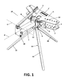
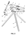
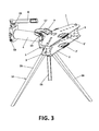
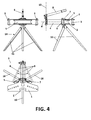
- the bending machine proposed by the invention comprises a base body (12) integral with a hydraulic cylinder (4) and to which there are anchored an upper plate (1) and a lower plate (2) between which there are arranged two guide rollers (3) which can be positioned in a plurality of positions between said two plates (1, 2) as a result of a plurality of holes arranged at specific distances in both plates.
- Said hydraulic cylinder (4) which can actuate according to an axis of movement (4') has associated therewith at the end of the rod an interchangeable bending die (5), having a curved convex surface intended for contacting the pipe to be bent, such that the chosen bending die (5) produces the desired bent on the pipe.
- an interchangeable bending die (5) having a curved convex surface intended for contacting the pipe to be bent, such that the chosen bending die (5) produces the desired bent on the pipe.
- the lower plate (2) is fixed to the base body (12) integral with the hydraulic cylinder (4) by means of lower anchoring elements (6) consisting of L-shaped flat bars, each of which has two anchoring points, keeping the lower plate (2) in a plane parallel to the axis of movement (4').
- the upper plate (1) is fixed to the base body (12) by means of upper anchoring elements (7) consisting of clamps, each of which has an anchoring point, keeping the upper plate (1) parallel to the lower plate (2) as a result of it being fixed to the base body (12) and supported on the guide rollers (3) which are in turn supported on the lower plate (2).
- both the L-shaped flat bars (6) and the clamps (7) have open grooves (6', 7') which are associated with two positioning notches (1", 2") arranged both in the upper plate (1) and in the lower plate (2), in order to assure that the attachment between them maintains the orthogonal position thereof.
- the attachment between the clamps (7) and the base body (12) by means of a bolt (19) allows pivoting the upper plate (1) on the upper anchoring elements (7), allowing access to the guide rollers (3) and the bending die (5) to adapt the operation to different pipe sizes.
- each upper anchoring element (7) coincides with one of the anchoring points of each lower anchoring element (6), specifically with the upper anchoring element, such that by coinciding said anchoring the alignment between the plates and the hydraulic cylinder is further assured.
- the bending machine comprises a drive lever (8) located in the hydraulic cylinder at an end opposite the base body (12).
- Said drive lever (8) can actuate the hydraulic cylinder (4) by means of rotating the lever with respect to a drive axis (9) contained in a plane parallel to the plates (1, 2).
- the drive lever (8) can also rotate with respect to an axis of rotation (10) which is perpendicular both to the axis of movement (4') and to the drive axis (9), i.e., a vertical axis, without this modifying the position of the axis of movement (4') itself.
- This rotation is allowed by means of a bushing (11) made by stamping, as seen in Figure 8 , arranged on the hydraulic cylinder (4).
- the rotation of the drive lever (8) with respect to the axis of rotation (10) is limited between two limit positions defined by the contact between two lugs (13) of the bushing (11), which is arranged on a recess, and two stop areas located in the hydraulic cylinder (4).
- the machine comprises a support element (14) for supporting the machine on a surface, for which said support element (14) comprises an upper projection (15) which can be housed in a hole located in the lower plate (2).
- the support element (14) consists of a tripod comprising three collapsible legs (16) which can be deployed towards a central position to make transport easier.
- the machine comprises a collapsible handle (17) associated with the anchoring bolt (19) fixing the upper plate.
- the plates (1, 2) comprising handles (1', 2') for manipulation and manual transport by a user is also contemplated.
- the handles (1', 2') of the plates (1, 2) can be covered by a plastic material for a better grip and comfort.
- the main purpose of the handle (1') of the upper plate (1) together with the pivoting handle (17) is to enable lifting/lowering the body from/onto the support element (14) easily.
- both handles (1', 2') of the plates (1, 2) can be used to enable, in relation to the wheels (18) arranged in the lower part of the end of the hydraulic cylinder (4) opposite the base body (12), comfortably moving the body of the bending machine.
Landscapes
- Engineering & Computer Science (AREA)
- Mechanical Engineering (AREA)
- Bending Of Plates, Rods, And Pipes (AREA)
Priority Applications (2)
| Application Number | Priority Date | Filing Date | Title |
|---|---|---|---|
| EP14382340.9A EP2995393B1 (fr) | 2014-09-11 | 2014-09-11 | Cintreuse |
| ES14382340T ES2781593T3 (es) | 2014-09-11 | 2014-09-11 | Máquina curvadora |
Applications Claiming Priority (1)
| Application Number | Priority Date | Filing Date | Title |
|---|---|---|---|
| EP14382340.9A EP2995393B1 (fr) | 2014-09-11 | 2014-09-11 | Cintreuse |
Publications (2)
| Publication Number | Publication Date |
|---|---|
| EP2995393A1 true EP2995393A1 (fr) | 2016-03-16 |
| EP2995393B1 EP2995393B1 (fr) | 2020-01-01 |
Family
ID=51868158
Family Applications (1)
| Application Number | Title | Priority Date | Filing Date |
|---|---|---|---|
| EP14382340.9A Active EP2995393B1 (fr) | 2014-09-11 | 2014-09-11 | Cintreuse |
Country Status (2)
| Country | Link |
|---|---|
| EP (1) | EP2995393B1 (fr) |
| ES (1) | ES2781593T3 (fr) |
Cited By (7)
| Publication number | Priority date | Publication date | Assignee | Title |
|---|---|---|---|---|
| CN109226382A (zh) * | 2018-10-25 | 2019-01-18 | 海盐新星机电有限公司 | 一种可调节弯曲角度的手动式液压弯管机 |
| CN110153247A (zh) * | 2019-07-08 | 2019-08-23 | 中国地震局工程力学研究所 | 一种简易钢管弯管机 |
| CN110238252A (zh) * | 2019-06-17 | 2019-09-17 | 国家能源投资集团有限责任公司 | 弧形扁钢制作装置以及扁钢角接处的连接方法 |
| CN110918711A (zh) * | 2018-09-20 | 2020-03-27 | 张家港百舸光电科技有限公司 | 一种稳定性高的多功能弯管机 |
| CN110918706A (zh) * | 2018-09-20 | 2020-03-27 | 张家港百舸光电科技有限公司 | 一种新型防震弯管机 |
| CN112191714A (zh) * | 2020-10-28 | 2021-01-08 | 上海市地质勘查技术研究院 | 一种方便钢管取出的岩土工程用弯管机 |
| CN113231505A (zh) * | 2021-04-28 | 2021-08-10 | 嘉兴市双圆机械制造股份有限公司 | 一种高效的自动弯管机 |
Citations (8)
| Publication number | Priority date | Publication date | Assignee | Title |
|---|---|---|---|---|
| DE1026157B (de) * | 1957-02-01 | 1958-03-13 | Paul Schmidt | Biegevorrichtung |
| US2867261A (en) * | 1955-02-23 | 1959-01-06 | Blackhawk Mfg Co | Pipe bender with bend indicator means on pivotal reaction blocks |
| US2871908A (en) * | 1956-11-30 | 1959-02-03 | Blackhawk Mfg Co | Art of bending and ejecting bent pipes |
| DE1918949A1 (de) * | 1969-04-15 | 1970-10-22 | Fritz Fischer | Rohrbiegevorrichtung |
| CN2406744Y (zh) | 2000-01-28 | 2000-11-22 | 庄宗超 | 一种便携式手动弯管机 |
| EP2181780A1 (fr) | 2008-10-28 | 2010-05-05 | CML International S.P.A. | Cintreuse à cintrer les tubes avec une transmission du mouvement à l'outil de cintrage améliorée |
| DE102011118654A1 (de) * | 2011-11-12 | 2013-05-16 | REMS-WERK Christian Föll und Söhne GmbH | Abdrückvorrichtung zum Herausdrücken von gebogenen Rohren aus Biegesegmenten von Biegeeinrichtungen |
| CN203678956U (zh) | 2013-12-30 | 2014-07-02 | 神旺工业有限公司 | 弯管器 |
-
2014
- 2014-09-11 ES ES14382340T patent/ES2781593T3/es active Active
- 2014-09-11 EP EP14382340.9A patent/EP2995393B1/fr active Active
Patent Citations (8)
| Publication number | Priority date | Publication date | Assignee | Title |
|---|---|---|---|---|
| US2867261A (en) * | 1955-02-23 | 1959-01-06 | Blackhawk Mfg Co | Pipe bender with bend indicator means on pivotal reaction blocks |
| US2871908A (en) * | 1956-11-30 | 1959-02-03 | Blackhawk Mfg Co | Art of bending and ejecting bent pipes |
| DE1026157B (de) * | 1957-02-01 | 1958-03-13 | Paul Schmidt | Biegevorrichtung |
| DE1918949A1 (de) * | 1969-04-15 | 1970-10-22 | Fritz Fischer | Rohrbiegevorrichtung |
| CN2406744Y (zh) | 2000-01-28 | 2000-11-22 | 庄宗超 | 一种便携式手动弯管机 |
| EP2181780A1 (fr) | 2008-10-28 | 2010-05-05 | CML International S.P.A. | Cintreuse à cintrer les tubes avec une transmission du mouvement à l'outil de cintrage améliorée |
| DE102011118654A1 (de) * | 2011-11-12 | 2013-05-16 | REMS-WERK Christian Föll und Söhne GmbH | Abdrückvorrichtung zum Herausdrücken von gebogenen Rohren aus Biegesegmenten von Biegeeinrichtungen |
| CN203678956U (zh) | 2013-12-30 | 2014-07-02 | 神旺工业有限公司 | 弯管器 |
Cited By (10)
| Publication number | Priority date | Publication date | Assignee | Title |
|---|---|---|---|---|
| CN110918711A (zh) * | 2018-09-20 | 2020-03-27 | 张家港百舸光电科技有限公司 | 一种稳定性高的多功能弯管机 |
| CN110918706A (zh) * | 2018-09-20 | 2020-03-27 | 张家港百舸光电科技有限公司 | 一种新型防震弯管机 |
| CN109226382A (zh) * | 2018-10-25 | 2019-01-18 | 海盐新星机电有限公司 | 一种可调节弯曲角度的手动式液压弯管机 |
| CN110238252A (zh) * | 2019-06-17 | 2019-09-17 | 国家能源投资集团有限责任公司 | 弧形扁钢制作装置以及扁钢角接处的连接方法 |
| CN110153247A (zh) * | 2019-07-08 | 2019-08-23 | 中国地震局工程力学研究所 | 一种简易钢管弯管机 |
| CN110153247B (zh) * | 2019-07-08 | 2024-02-02 | 中国地震局工程力学研究所 | 一种简易钢管弯管机 |
| CN112191714A (zh) * | 2020-10-28 | 2021-01-08 | 上海市地质勘查技术研究院 | 一种方便钢管取出的岩土工程用弯管机 |
| CN112191714B (zh) * | 2020-10-28 | 2022-08-30 | 上海市地质勘查技术研究院 | 一种方便钢管取出的岩土工程用弯管机 |
| CN113231505A (zh) * | 2021-04-28 | 2021-08-10 | 嘉兴市双圆机械制造股份有限公司 | 一种高效的自动弯管机 |
| CN113231505B (zh) * | 2021-04-28 | 2023-01-24 | 嘉兴市双圆机械制造股份有限公司 | 一种高效的自动弯管机 |
Also Published As
| Publication number | Publication date |
|---|---|
| ES2781593T3 (es) | 2020-09-03 |
| EP2995393B1 (fr) | 2020-01-01 |
Similar Documents
| Publication | Publication Date | Title |
|---|---|---|
| EP2995393B1 (fr) | Cintreuse | |
| KR20140131282A (ko) | 긴 가공물을 우측 및 좌측으로 굽힘 가공하기 위한 금형 및 상대 금형 방식의 벤딩 머신 | |
| KR101523323B1 (ko) | 엘보우성형기 | |
| JP2015116594A (ja) | 鉄筋曲げ機および鉄筋スペーサー | |
| KR101450182B1 (ko) | 평탄도 확보를 위한 파이프 벤딩기 | |
| CN103170554A (zh) | 用于钢筋一次成型的自动成型机 | |
| CN203635810U (zh) | 钢筋弯圆装置 | |
| KR20130021663A (ko) | 파이프 벤딩 장치 | |
| KR101363072B1 (ko) | 프레스 타공용 금형의 금속판 고정장치 | |
| KR100965928B1 (ko) | 티형관 성형장치 | |
| JP4315217B2 (ja) | スイング式加工装置 | |
| CN103100610A (zh) | 一种杆式钢筋自动成型机 | |
| CN106424250A (zh) | 一种钢管快速折弯装置及其折弯方法 | |
| JP4450244B2 (ja) | スイング式加工装置 | |
| KR102187319B1 (ko) | 휀스 장식용 철재부재의 휨 가공장치 | |
| US7000447B1 (en) | Tube bending machine | |
| CN103611844A (zh) | 钢筋弯圆装置 | |
| JP4450243B2 (ja) | スイング式加工装置 | |
| CN104492859A (zh) | 移动自压式校直机 | |
| US608725A (en) | Punching-iviachine | |
| KR20140005473A (ko) | 프레스 벤딩장치 | |
| AU2013101432B4 (en) | A Portable Bending Tool | |
| KR20220047025A (ko) | 철사 절곡장치 | |
| CN104525701B (zh) | 一种液压阀底板连续成型加工系列的多向打孔成型装置 | |
| JP3198947U (ja) | 鉄筋の挾持装置及び鉄筋の挾持システム |
Legal Events
| Date | Code | Title | Description |
|---|---|---|---|
| PUAI | Public reference made under article 153(3) epc to a published international application that has entered the european phase |
Free format text: ORIGINAL CODE: 0009012 |
|
| AK | Designated contracting states |
Kind code of ref document: A1 Designated state(s): AL AT BE BG CH CY CZ DE DK EE ES FI FR GB GR HR HU IE IS IT LI LT LU LV MC MK MT NL NO PL PT RO RS SE SI SK SM TR |
|
| AX | Request for extension of the european patent |
Extension state: BA ME |
|
| 17P | Request for examination filed |
Effective date: 20160916 |
|
| RBV | Designated contracting states (corrected) |
Designated state(s): AL AT BE BG CH CY CZ DE DK EE ES FI FR GB GR HR HU IE IS IT LI LT LU LV MC MK MT NL NO PL PT RO RS SE SI SK SM TR |
|
| STAA | Information on the status of an ep patent application or granted ep patent |
Free format text: STATUS: EXAMINATION IS IN PROGRESS |
|
| 17Q | First examination report despatched |
Effective date: 20181122 |
|
| GRAP | Despatch of communication of intention to grant a patent |
Free format text: ORIGINAL CODE: EPIDOSNIGR1 |
|
| STAA | Information on the status of an ep patent application or granted ep patent |
Free format text: STATUS: GRANT OF PATENT IS INTENDED |
|
| INTG | Intention to grant announced |
Effective date: 20190828 |
|
| GRAS | Grant fee paid |
Free format text: ORIGINAL CODE: EPIDOSNIGR3 |
|
| GRAA | (expected) grant |
Free format text: ORIGINAL CODE: 0009210 |
|
| STAA | Information on the status of an ep patent application or granted ep patent |
Free format text: STATUS: THE PATENT HAS BEEN GRANTED |
|
| AK | Designated contracting states |
Kind code of ref document: B1 Designated state(s): AL AT BE BG CH CY CZ DE DK EE ES FI FR GB GR HR HU IE IS IT LI LT LU LV MC MK MT NL NO PL PT RO RS SE SI SK SM TR |
|
| REG | Reference to a national code |
Ref country code: GB Ref legal event code: FG4D |
|
| REG | Reference to a national code |
Ref country code: CH Ref legal event code: EP Ref country code: AT Ref legal event code: REF Ref document number: 1219131 Country of ref document: AT Kind code of ref document: T Effective date: 20200115 |
|
| REG | Reference to a national code |
Ref country code: DE Ref legal event code: R096 Ref document number: 602014059224 Country of ref document: DE |
|
| REG | Reference to a national code |
Ref country code: IE Ref legal event code: FG4D |
|
| REG | Reference to a national code |
Ref country code: NL Ref legal event code: MP Effective date: 20200101 |
|
| REG | Reference to a national code |
Ref country code: LT Ref legal event code: MG4D |
|
| PG25 | Lapsed in a contracting state [announced via postgrant information from national office to epo] |
Ref country code: NL Free format text: LAPSE BECAUSE OF FAILURE TO SUBMIT A TRANSLATION OF THE DESCRIPTION OR TO PAY THE FEE WITHIN THE PRESCRIBED TIME-LIMIT Effective date: 20200101 Ref country code: RS Free format text: LAPSE BECAUSE OF FAILURE TO SUBMIT A TRANSLATION OF THE DESCRIPTION OR TO PAY THE FEE WITHIN THE PRESCRIBED TIME-LIMIT Effective date: 20200101 Ref country code: LT Free format text: LAPSE BECAUSE OF FAILURE TO SUBMIT A TRANSLATION OF THE DESCRIPTION OR TO PAY THE FEE WITHIN THE PRESCRIBED TIME-LIMIT Effective date: 20200101 Ref country code: FI Free format text: LAPSE BECAUSE OF FAILURE TO SUBMIT A TRANSLATION OF THE DESCRIPTION OR TO PAY THE FEE WITHIN THE PRESCRIBED TIME-LIMIT Effective date: 20200101 Ref country code: CZ Free format text: LAPSE BECAUSE OF FAILURE TO SUBMIT A TRANSLATION OF THE DESCRIPTION OR TO PAY THE FEE WITHIN THE PRESCRIBED TIME-LIMIT Effective date: 20200101 Ref country code: PT Free format text: LAPSE BECAUSE OF FAILURE TO SUBMIT A TRANSLATION OF THE DESCRIPTION OR TO PAY THE FEE WITHIN THE PRESCRIBED TIME-LIMIT Effective date: 20200527 Ref country code: NO Free format text: LAPSE BECAUSE OF FAILURE TO SUBMIT A TRANSLATION OF THE DESCRIPTION OR TO PAY THE FEE WITHIN THE PRESCRIBED TIME-LIMIT Effective date: 20200401 |
|
| PG25 | Lapsed in a contracting state [announced via postgrant information from national office to epo] |
Ref country code: LV Free format text: LAPSE BECAUSE OF FAILURE TO SUBMIT A TRANSLATION OF THE DESCRIPTION OR TO PAY THE FEE WITHIN THE PRESCRIBED TIME-LIMIT Effective date: 20200101 Ref country code: SE Free format text: LAPSE BECAUSE OF FAILURE TO SUBMIT A TRANSLATION OF THE DESCRIPTION OR TO PAY THE FEE WITHIN THE PRESCRIBED TIME-LIMIT Effective date: 20200101 Ref country code: BG Free format text: LAPSE BECAUSE OF FAILURE TO SUBMIT A TRANSLATION OF THE DESCRIPTION OR TO PAY THE FEE WITHIN THE PRESCRIBED TIME-LIMIT Effective date: 20200401 Ref country code: IS Free format text: LAPSE BECAUSE OF FAILURE TO SUBMIT A TRANSLATION OF THE DESCRIPTION OR TO PAY THE FEE WITHIN THE PRESCRIBED TIME-LIMIT Effective date: 20200501 Ref country code: GR Free format text: LAPSE BECAUSE OF FAILURE TO SUBMIT A TRANSLATION OF THE DESCRIPTION OR TO PAY THE FEE WITHIN THE PRESCRIBED TIME-LIMIT Effective date: 20200402 Ref country code: HR Free format text: LAPSE BECAUSE OF FAILURE TO SUBMIT A TRANSLATION OF THE DESCRIPTION OR TO PAY THE FEE WITHIN THE PRESCRIBED TIME-LIMIT Effective date: 20200101 |
|
| REG | Reference to a national code |
Ref country code: ES Ref legal event code: FG2A Ref document number: 2781593 Country of ref document: ES Kind code of ref document: T3 Effective date: 20200903 |
|
| REG | Reference to a national code |
Ref country code: DE Ref legal event code: R097 Ref document number: 602014059224 Country of ref document: DE |
|
| PG25 | Lapsed in a contracting state [announced via postgrant information from national office to epo] |
Ref country code: SK Free format text: LAPSE BECAUSE OF FAILURE TO SUBMIT A TRANSLATION OF THE DESCRIPTION OR TO PAY THE FEE WITHIN THE PRESCRIBED TIME-LIMIT Effective date: 20200101 Ref country code: RO Free format text: LAPSE BECAUSE OF FAILURE TO SUBMIT A TRANSLATION OF THE DESCRIPTION OR TO PAY THE FEE WITHIN THE PRESCRIBED TIME-LIMIT Effective date: 20200101 Ref country code: SM Free format text: LAPSE BECAUSE OF FAILURE TO SUBMIT A TRANSLATION OF THE DESCRIPTION OR TO PAY THE FEE WITHIN THE PRESCRIBED TIME-LIMIT Effective date: 20200101 Ref country code: EE Free format text: LAPSE BECAUSE OF FAILURE TO SUBMIT A TRANSLATION OF THE DESCRIPTION OR TO PAY THE FEE WITHIN THE PRESCRIBED TIME-LIMIT Effective date: 20200101 Ref country code: DK Free format text: LAPSE BECAUSE OF FAILURE TO SUBMIT A TRANSLATION OF THE DESCRIPTION OR TO PAY THE FEE WITHIN THE PRESCRIBED TIME-LIMIT Effective date: 20200101 |
|
| PLBE | No opposition filed within time limit |
Free format text: ORIGINAL CODE: 0009261 |
|
| STAA | Information on the status of an ep patent application or granted ep patent |
Free format text: STATUS: NO OPPOSITION FILED WITHIN TIME LIMIT |
|
| REG | Reference to a national code |
Ref country code: AT Ref legal event code: MK05 Ref document number: 1219131 Country of ref document: AT Kind code of ref document: T Effective date: 20200101 |
|
| 26N | No opposition filed |
Effective date: 20201002 |
|
| PG25 | Lapsed in a contracting state [announced via postgrant information from national office to epo] |
Ref country code: AT Free format text: LAPSE BECAUSE OF FAILURE TO SUBMIT A TRANSLATION OF THE DESCRIPTION OR TO PAY THE FEE WITHIN THE PRESCRIBED TIME-LIMIT Effective date: 20200101 Ref country code: IT Free format text: LAPSE BECAUSE OF FAILURE TO SUBMIT A TRANSLATION OF THE DESCRIPTION OR TO PAY THE FEE WITHIN THE PRESCRIBED TIME-LIMIT Effective date: 20200101 |
|
| PG25 | Lapsed in a contracting state [announced via postgrant information from national office to epo] |
Ref country code: SI Free format text: LAPSE BECAUSE OF FAILURE TO SUBMIT A TRANSLATION OF THE DESCRIPTION OR TO PAY THE FEE WITHIN THE PRESCRIBED TIME-LIMIT Effective date: 20200101 Ref country code: PL Free format text: LAPSE BECAUSE OF FAILURE TO SUBMIT A TRANSLATION OF THE DESCRIPTION OR TO PAY THE FEE WITHIN THE PRESCRIBED TIME-LIMIT Effective date: 20200101 |
|
| PG25 | Lapsed in a contracting state [announced via postgrant information from national office to epo] |
Ref country code: MC Free format text: LAPSE BECAUSE OF FAILURE TO SUBMIT A TRANSLATION OF THE DESCRIPTION OR TO PAY THE FEE WITHIN THE PRESCRIBED TIME-LIMIT Effective date: 20200101 |
|
| REG | Reference to a national code |
Ref country code: CH Ref legal event code: PL |
|
| REG | Reference to a national code |
Ref country code: BE Ref legal event code: MM Effective date: 20200930 |
|
| PG25 | Lapsed in a contracting state [announced via postgrant information from national office to epo] |
Ref country code: LU Free format text: LAPSE BECAUSE OF NON-PAYMENT OF DUE FEES Effective date: 20200911 |
|
| PG25 | Lapsed in a contracting state [announced via postgrant information from national office to epo] |
Ref country code: CH Free format text: LAPSE BECAUSE OF NON-PAYMENT OF DUE FEES Effective date: 20200930 Ref country code: BE Free format text: LAPSE BECAUSE OF NON-PAYMENT OF DUE FEES Effective date: 20200930 Ref country code: IE Free format text: LAPSE BECAUSE OF NON-PAYMENT OF DUE FEES Effective date: 20200911 Ref country code: LI Free format text: LAPSE BECAUSE OF NON-PAYMENT OF DUE FEES Effective date: 20200930 |
|
| PG25 | Lapsed in a contracting state [announced via postgrant information from national office to epo] |
Ref country code: TR Free format text: LAPSE BECAUSE OF FAILURE TO SUBMIT A TRANSLATION OF THE DESCRIPTION OR TO PAY THE FEE WITHIN THE PRESCRIBED TIME-LIMIT Effective date: 20200101 Ref country code: MT Free format text: LAPSE BECAUSE OF FAILURE TO SUBMIT A TRANSLATION OF THE DESCRIPTION OR TO PAY THE FEE WITHIN THE PRESCRIBED TIME-LIMIT Effective date: 20200101 Ref country code: CY Free format text: LAPSE BECAUSE OF FAILURE TO SUBMIT A TRANSLATION OF THE DESCRIPTION OR TO PAY THE FEE WITHIN THE PRESCRIBED TIME-LIMIT Effective date: 20200101 |
|
| PG25 | Lapsed in a contracting state [announced via postgrant information from national office to epo] |
Ref country code: MK Free format text: LAPSE BECAUSE OF FAILURE TO SUBMIT A TRANSLATION OF THE DESCRIPTION OR TO PAY THE FEE WITHIN THE PRESCRIBED TIME-LIMIT Effective date: 20200101 Ref country code: AL Free format text: LAPSE BECAUSE OF FAILURE TO SUBMIT A TRANSLATION OF THE DESCRIPTION OR TO PAY THE FEE WITHIN THE PRESCRIBED TIME-LIMIT Effective date: 20200101 |
|
| REG | Reference to a national code |
Ref country code: GB Ref legal event code: 732E Free format text: REGISTERED BETWEEN 20231214 AND 20231220 |
|
| REG | Reference to a national code |
Ref country code: DE Ref legal event code: R081 Ref document number: 602014059224 Country of ref document: DE Owner name: NEW MEGA XXI, S.L., ES Free format text: FORMER OWNER: MELCHOR GABILONDO, S.A., BERRIZ, BIZKAIA, ES |
|
| REG | Reference to a national code |
Ref country code: ES Ref legal event code: PC2A Owner name: NEW MEGA XXI, S.L. Effective date: 20240626 |
|
| PGFP | Annual fee paid to national office [announced via postgrant information from national office to epo] |
Ref country code: DE Payment date: 20250919 Year of fee payment: 12 |
|
| PGFP | Annual fee paid to national office [announced via postgrant information from national office to epo] |
Ref country code: GB Payment date: 20250902 Year of fee payment: 12 |
|
| PGFP | Annual fee paid to national office [announced via postgrant information from national office to epo] |
Ref country code: FR Payment date: 20250902 Year of fee payment: 12 |
|
| PGFP | Annual fee paid to national office [announced via postgrant information from national office to epo] |
Ref country code: ES Payment date: 20251003 Year of fee payment: 12 |