EP2995402A1 - Appareils et procédés de traitement d'une zone confinée d'une pièce à usiner - Google Patents
Appareils et procédés de traitement d'une zone confinée d'une pièce à usiner Download PDFInfo
- Publication number
- EP2995402A1 EP2995402A1 EP15184071.7A EP15184071A EP2995402A1 EP 2995402 A1 EP2995402 A1 EP 2995402A1 EP 15184071 A EP15184071 A EP 15184071A EP 2995402 A1 EP2995402 A1 EP 2995402A1
- Authority
- EP
- European Patent Office
- Prior art keywords
- drill
- clamp
- pressure foot
- workpiece
- flat angle
- Prior art date
- Legal status (The legal status is an assumption and is not a legal conclusion. Google has not performed a legal analysis and makes no representation as to the accuracy of the status listed.)
- Granted
Links
Images







Classifications
-
- B—PERFORMING OPERATIONS; TRANSPORTING
- B23—MACHINE TOOLS; METAL-WORKING NOT OTHERWISE PROVIDED FOR
- B23Q—DETAILS, COMPONENTS, OR ACCESSORIES FOR MACHINE TOOLS, e.g. ARRANGEMENTS FOR COPYING OR CONTROLLING; MACHINE TOOLS IN GENERAL CHARACTERISED BY THE CONSTRUCTION OF PARTICULAR DETAILS OR COMPONENTS; COMBINATIONS OR ASSOCIATIONS OF METAL-WORKING MACHINES, NOT DIRECTED TO A PARTICULAR RESULT
- B23Q9/00—Arrangements for supporting or guiding portable metal-working machines or apparatus
- B23Q9/0014—Portable machines provided with or cooperating with guide means supported directly by the workpiece during action
- B23Q9/0042—Portable machines provided with or cooperating with guide means supported directly by the workpiece during action the guide means being fixed only on the workpiece
-
- B—PERFORMING OPERATIONS; TRANSPORTING
- B23—MACHINE TOOLS; METAL-WORKING NOT OTHERWISE PROVIDED FOR
- B23B—TURNING; BORING
- B23B47/00—Constructional features of components specially designed for boring or drilling machines; Accessories therefor
- B23B47/26—Liftable or lowerable drill heads or headstocks; Balancing arrangements therefor
-
- B—PERFORMING OPERATIONS; TRANSPORTING
- B23—MACHINE TOOLS; METAL-WORKING NOT OTHERWISE PROVIDED FOR
- B23B—TURNING; BORING
- B23B41/00—Boring or drilling machines or devices specially adapted for particular work; Accessories specially adapted therefor
-
- B—PERFORMING OPERATIONS; TRANSPORTING
- B23—MACHINE TOOLS; METAL-WORKING NOT OTHERWISE PROVIDED FOR
- B23B—TURNING; BORING
- B23B35/00—Methods for boring or drilling, or for working essentially requiring the use of boring or drilling machines; Use of auxiliary equipment in connection with such methods
-
- B—PERFORMING OPERATIONS; TRANSPORTING
- B23—MACHINE TOOLS; METAL-WORKING NOT OTHERWISE PROVIDED FOR
- B23B—TURNING; BORING
- B23B39/00—General-purpose boring or drilling machines or devices; Sets of boring and/or drilling machines
-
- B—PERFORMING OPERATIONS; TRANSPORTING
- B23—MACHINE TOOLS; METAL-WORKING NOT OTHERWISE PROVIDED FOR
- B23Q—DETAILS, COMPONENTS, OR ACCESSORIES FOR MACHINE TOOLS, e.g. ARRANGEMENTS FOR COPYING OR CONTROLLING; MACHINE TOOLS IN GENERAL CHARACTERISED BY THE CONSTRUCTION OF PARTICULAR DETAILS OR COMPONENTS; COMBINATIONS OR ASSOCIATIONS OF METAL-WORKING MACHINES, NOT DIRECTED TO A PARTICULAR RESULT
- B23Q5/00—Driving or feeding mechanisms; Control arrangements therefor
- B23Q5/02—Driving main working members
- B23Q5/04—Driving main working members rotary shafts, e.g. working-spindles
- B23Q5/043—Accessories for spindle drives
- B23Q5/046—Offset spindle drives
-
- B—PERFORMING OPERATIONS; TRANSPORTING
- B25—HAND TOOLS; PORTABLE POWER-DRIVEN TOOLS; MANIPULATORS
- B25J—MANIPULATORS; CHAMBERS PROVIDED WITH MANIPULATION DEVICES
- B25J11/00—Manipulators not otherwise provided for
- B25J11/005—Manipulators for mechanical processing tasks
-
- B—PERFORMING OPERATIONS; TRANSPORTING
- B25—HAND TOOLS; PORTABLE POWER-DRIVEN TOOLS; MANIPULATORS
- B25J—MANIPULATORS; CHAMBERS PROVIDED WITH MANIPULATION DEVICES
- B25J15/00—Gripping heads and other end effectors
- B25J15/0095—Gripping heads and other end effectors with an external support, i.e. a support which does not belong to the manipulator or the object to be gripped, e.g. for maintaining the gripping head in an accurate position, guiding it or preventing vibrations
-
- B—PERFORMING OPERATIONS; TRANSPORTING
- B23—MACHINE TOOLS; METAL-WORKING NOT OTHERWISE PROVIDED FOR
- B23B—TURNING; BORING
- B23B2215/00—Details of workpieces
- B23B2215/04—Aircraft components
-
- B—PERFORMING OPERATIONS; TRANSPORTING
- B23—MACHINE TOOLS; METAL-WORKING NOT OTHERWISE PROVIDED FOR
- B23B—TURNING; BORING
- B23B2250/00—Compensating adverse effects during turning, boring or drilling
- B23B2250/12—Cooling and lubrication
-
- B—PERFORMING OPERATIONS; TRANSPORTING
- B23—MACHINE TOOLS; METAL-WORKING NOT OTHERWISE PROVIDED FOR
- B23B—TURNING; BORING
- B23B2270/00—Details of turning, boring or drilling machines, processes or tools not otherwise provided for
- B23B2270/08—Clamping mechanisms; Provisions for clamping
-
- B—PERFORMING OPERATIONS; TRANSPORTING
- B23—MACHINE TOOLS; METAL-WORKING NOT OTHERWISE PROVIDED FOR
- B23B—TURNING; BORING
- B23B2270/00—Details of turning, boring or drilling machines, processes or tools not otherwise provided for
- B23B2270/62—Use of suction
-
- B—PERFORMING OPERATIONS; TRANSPORTING
- B25—HAND TOOLS; PORTABLE POWER-DRIVEN TOOLS; MANIPULATORS
- B25J—MANIPULATORS; CHAMBERS PROVIDED WITH MANIPULATION DEVICES
- B25J11/00—Manipulators not otherwise provided for
- B25J11/005—Manipulators for mechanical processing tasks
- B25J11/0055—Cutting
Definitions
- An end effector is a device at the end of a robotic arm, designed to interact with the environment and/or a workpiece.
- the exact configuration of the end effector may depend on the particular application of the robot and/or the particular process be performed on the workpiece.
- the end effector may manipulate the workpiece and/or position one or more machining tools relative to the workpiece and/or a surface to be processed.
- the configuration of the end effector utilized to manipulate and/or process the workpiece may make accessing a processing location, particularly one located in a confined area or near an obstruction, difficult or even impossible. Accordingly, certain operations may require manual processing, for example, utilizing hand tools. Manual processing of the workpiece may increase cost and process cycle time of the workpiece.
- the apparatus comprises an end effector.
- the end effector comprises a pressure foot, a clamp linearly movable relative to the pressure foot along the drilling axis, and a flat angle drill linearly movable relative to the pressure foot along the drilling axis.
- the present disclosure relates to a drill bracket for coupling a flat angle drill to a spindle of an end effector.
- the flat angle drill comprises a housing, a hexagonal retainer connected to the housing, and a drilling axis passing through the housing.
- the drill bracket comprises a drill brace capable of generating a reaction force F2 equal and opposite to an action force F1 transmittable to the flat angle drill along the drilling axis during a drilling operation, and a split clamp capable of preventing rotation of the housing of the flat angle drill relative to the drill brace.
- Yet another example of the present disclosure relates to a method for processing a drilling location in a confined area of a workpiece along a drilling axis using an end effector.
- the method comprises positioning the end effector relative to the drilling location of the workpiece, clamping the workpiece between a clamp of the end effector and a pressure foot of the end effector, wherein the pressure foot supports the clamp movable relative to the pressure foot, and drilling the workpiece with a flat angle drill of the end effector.
- solid lines, if any, connecting various elements and/or components may represent mechanical, electrical, fluid, optical, electromagnetic and other couplings and/or combinations thereof.
- "coupled” means associated directly as well as indirectly.
- a member A may be directly associated with a member B, or may be indirectly associated therewith, e.g., via another member C. It will be understood that not all relationships between the various disclosed elements are necessarily represented. Accordingly, couplings other than those depicted in the block diagrams may also exist.
- Dashed lines, if any, connecting the various elements and/or components represent couplings similar in function and purpose to those represented by solid lines; however, couplings represented by the dashed lines may either be selectively provided or may relate to alternative or optional examples of the present disclosure.
- elements and/or components, if any, represented with dashed lines indicate alternative or optional examples of the present disclosure.
- Environmental elements, if any, are represented with dotted lines. Virtual imaginary elements may also be shown for clarity.
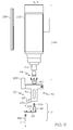
- FIG. 9 referred to above, the blocks may represent operations and/or portions thereof and lines connecting the various blocks do not imply any particular order or dependency of the operations or portions thereof.
- FIG. 9 and the accompanying disclosure describing the operations of the methods set forth herein should not be interpreted as necessarily determining a sequence in which the operations are to be performed. Rather, although one illustrative order is indicated, it is to be understood that the sequence of the operations may be modified when appropriate. Accordingly, certain operations may be performed in a different order or simultaneously. Additionally, those skilled in the art will appreciate that not all operations described need be performed.
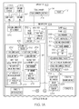
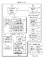
- Example 1 relates to apparatus 100 for processing workpiece 102 along drilling axis A.
- Apparatus 100 comprises end effector 104.
- End effector 104 comprises pressure foot 106, clamp 108 linearly movable relative to pressure foot 106 along drilling axis A, and flat angle drill 110 linearly movable relative to pressure foot 106 along drilling axis A.
- Drilling axis A is an axis along which a drilling operation is performed on workpiece 102.
- drilling axis A may be defined by an axis passing through flat angle drill 110 (e.g., drill bit 196 of flat angle drill 110) and workpiece 102 (e.g., surface of workpiece 102).
- drilling axis A may be defined by an axis passing through a center of drill bit 196 of flat angle drill 110 and normal to surface 198 of workpiece 102.
- drilling operation means any machining or cutting process that uses drill bit 196 to form (e.g., cut and/or enlarge) a hole of circular cross-section in solid materials.
- the drilling operation may include forming a fastening aperture (e.g., hole) in or through surface 198 or workpiece 102.
- apparatus 100 may also process workpiece 102 along one or more other axes that are different from drilling axis A.
- apparatus 100 may process workpiece 102 along an axis through which a milling operation is performed, for example, an axis that is substantially perpendicular to drilling axis A.
- along drilling axis A means motion in a direction coincident with or parallel to drilling axis A.
- clamp 108 being linearly movable relative to pressure foot 106 along drilling axis A may mean that clamp 108 is linearly movable relative to pressure foot 106 in a direction (or opposing directions) parallel to drilling axis A.
- flat angle drill 110 being linearly movable relative to pressure foot 106 along drilling axis A may mean that flat angle drill 110 is linearly movable relative to pressure foot 106 in a direction parallel to drilling axis A.
- workpiece 102 includes any object or article that is processed by apparatus 100.
- workpiece 102 may include a raw or partially finished component or part of an article of manufacture, such as a vehicle (e.g., an aircraft).
- workpiece 102 may include one or more surfaces 198 to be processed by apparatus 100.
- Surface 198 may include drilling location 148.
- Drilling location 148 may include a point of contact between surface 198 and drill bit 196 (e.g., location of the hole to be formed in surface 198).
- Drilling location 148 may be located in confined area 154 of workpiece 102.
- Confined area 154 may be defined by surface 198 and one or more obstructions 150.
- Obstruction 150 may include another surface, feature, and/or structure of workpiece 102 proximate (e.g., at or near) drilling location 148.
- obstruction 150 may include a flange extending (e.g., perpendicularly) from surface 198 proximate drilling location 148 or extending toward drilling location 148.
- obstruction 150 may include another surface of workpiece 102 spaced away from and located over, below, or beside drilling location 148.
- obstruction 150 may include surface textures (e.g., reinforcing ribs) disposed on surface 200 of workpiece 102 opposite drilling location 148 (e.g., being opposite of surface 198 upon which drilling location 148 is located).
- end effector 104 may be configured to position workpiece 102 between pressure foot 106 and clamp 108 prior to the drilling operation.
- End effector 104 may be configured to clamp workpiece 102 between pressure foot 106 and clamp 108, for example, avoiding obstruction 150, during a clamping operation.
- End effector 104 with flat angle drill 110 is configured to avoid obstruction 150 when being positioned relative to drilling location 148 (e.g., by aligning drilling axis A of flat angle drill 110 with drilling location 148) for performing a drilling operation on workpiece 102 (e.g., surface 198 of workpiece 102).
- clamping operation means applying a clamping force (e.g., a preload force) to workpiece 102.
- the clamping operation may include contacting surface 200 of workpiece 102 with clamp 108 and applying (e.g., exerting) action force F 3 upon workpiece 102 by clamp 108 and contacting surface 198 of workpiece 102 with pressure foot 106 and applying (e.g., exerting) reaction force F 4 upon workpiece 102 by pressure foot 106.
- Reaction force F 4 being equal and opposite to action force F 3 .
- flat angle drill 110 may be capable of accessing drilling location 148 within confined area 154 when positioned, by end effector 104, with respect to drilling location 148.
- Flat angle drill 110 may also be known as a "porkchop".
- flat angle drill 110 may include housing 126, hexagonal retainer 146, drive shank 206, and drill bit receiver 212.
- Housing 126 may include internal transmission (not shown) capable of translating rotational motion of drive shank 206 to rotational motion of drill bit receiver 212 and, thus, rotation of drill bit 196.
- Housing 126 may space drill bit receiver 212 away from drive shank 206 (e.g., drill bit 198 may be offset relative to drive shank 206 and spindle 118).
- Hexagonal retainer 146 may be rigidly connected to housing 126.
- Drive shank 206 may be operatively coupled to housing 126 (e.g., to internal transmission).
- Drive shank 206 may extend through and be freely rotatable relative to (e.g., within) hexagonal retainer 146.
- Drill bit receiver 212 may be operatively coupled to housing 126 (e.g., to internal transmission) and capable of receiving drill bit 196 and securing drill bit 196 to housing 126.
- drill bit 198 may be threadingly connected to drill bit receiver 212.
- drill bit receiver 212 may include internal threading and drill bit 196 may include external threading.
- the threading of drill bit 196 and drill bit receiver 212 may oppose a direction of rotation of drill bit 196 during the drilling operation (e.g., left-hand threading).
- flat angle drill 110 may be commercially available from Jiffy Air Tool, 2254 Conestoga Drive, Carson City, Nevada 89706.
- end effector 104 further comprises base 116, spindle 118 linearly movable relative to base 116 along drilling axis A, and drill bracket 120 fixed relative to spindle 118 and configured to retain flat angle drill 110 in a clocked orientation relative to drill bracket 120 and to brace flat angle drill 110 along drilling axis A.
- Flat angle drill 110 is configured to be operatively coupled to spindle 118.
- locked orientation means a rotational (e.g., angular) position of flat angle drill 110 relative to spindle 118 and drill bracket 120.
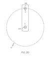
- spindle 118 may include rotational axis R ( FIGs. 4 , 11 and 20 ).
- the clocked orientation of the flat angle drill 110 may be the rotational (e.g., angular) position of the flat angle drill 110 about rotational axis R relative to spindle 118 and/or drill bracket 120.
- the clocked orientation may be defined by the rotational position of drilling axis A (e.g., passing through drill bit 196 and housing 126 of flat angle drill 110) relative to a fixed position of rotational axis R (e.g., passing through drill shank 206 of flat angle drill 110, drill bracket 120 and spindle 118).
- drilling axis A may have a rotational position of zero degrees relative to rotational axis R.
- spindle 118 may include motor (e.g., motor housing) 208 and drive shaft 210 operably coupled to motor 208.
- Motor 208 may include any electric motor capable of providing rotational speeds of drive shaft 210 suitable for the drilling operation.
- drive shank 210 of flat angle drill 110 may be operatively coupled to drive shaft 210 of spindle 118.
- drive shaft 210 may include a drive shank clamp 214 capable of attaching flat angle drill 110 to spindle 118 (e.g., holding and securing drive shank 206 to drive shaft 210).
- drive shank clamp 214 may include a collet and a collet nut capable of forming a collar around drive shank 206 to secure drive shank 206 to drive shaft 210.
- drive shank clamp 214 may include a chuck to secure drive shank 206 to drive shaft 210.
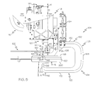
- Drill bracket 120 may engage hexagonal retainer 146 to retain flat angle drill 110 in the clocked orientation relative to drill bracket 120 and prevent rotation of flat angle drill 110 (e.g., housing 126) relative to drill bracket 120. Drill bracket 120 may also engage housing 126 to react to any torque applied to flat angle drill 110 during the drilling operation. As one example, and as best illustrated in FIG. 5 , drill bracket 120 may generate reaction force F 2 equal and opposite to action force F 1 (e.g., torque) transmitted to the flat angle drill 110 (e.g., housing 126) along the drilling axis A during the drilling operation.
- F 1 e.g., torque
- end effector 104 further comprises translation platform 182 linearly movable relative to base 116 along drilling axis A.
- Spindle 118 is linearly movable relative to translation platform 182 along drilling axis A.
- Pressure foot 106 is fixed relative to translation platform 182.
- translation platform 182 may be operably coupled to base 116.
- translation platform 182 may be movably connected to base 116 such that translation platform 182 is linearly movable relative to base 116 along drilling axis A.
- translation platform 182 may include rail 246 ( FIGs. 12 and 13 ). Rail 246 may be connected to rail and carriage bracket 248 of (e.g., connected to) base 116. Rail and carriage bracket 248 ( FIG. 15 ) may be capable of supporting translation platform 182 (e.g., rail 246) and restraining linear motion of translation platform 182 to only along drilling axis A relative to base 116.
- spindle 118 may be operatively coupled to translation platform 182.
- spindle 118 may be movably connected to transition platform 182 such that spindle 118 is linearly movable relative to translation platform 182 along drilling axis A.
- drill bracket 120 may be fixedly coupled to spindle 118.
- drill bracket 120 may be connected to and supported by spindle 118 at a fixed position relative to spindle 118.
- pressure foot 106 may be fixedly coupled to translation platform 182.
- pressure foot 106 may be connected to and supported by translation platform 182 at a fixed position relative to translation platform 182.
- clamp 108 may be operatively coupled to pressure foot 106.
- clamp 108 may be movably connected to pressure foot 106 such that clamp 108 is linearly movable relative to pressure foot 106.
- flat angle drill 110 may be fixedly coupled to drill bracket 120 and operatively coupled to spindle 118.
- flat angle drill 100 may be operatively connected to and supported by spindle 118 at a fixed position relative to spindle 118 and drill bracket 120.
- Flat angle drill 110 may also be connected to and retained by drill bracket 120 at the clocked orientation relative to drill bracket 120.
- linear movement of translation platform 182 relative to base 116 may linearly move and position spindle 118, pressure foot 106, drill bracket 120, flat angle drill 110, and clamp 108 along drilling axis A.
- Linear movement of spindle 118 relative to translation platform 182 may move and position spindle 118, drill bracket 120, and flat angle drill 110 along drilling axis A.
- Linear movement of clamp 108 relative to pressure foot 106 may move and position clamp 108 along drilling axis A.
- end effector 104 further comprises spindle drive mechanism 124 to linearly translate spindle 118 relative to translation platform 182 along drilling axis A, and clamp drive mechanism 184 to linearly translate clamp 108 relative to pressure foot 106 along drilling axis A.
- spindle drive mechanism 124 may include any linear drive mechanism or linear actuator 222 suitable to or capable of linearly moving spindle 118 relative to translation platform 182 along drilling axis A.
- spindle drive mechanism 124 e.g., linear actuator 222
- spindle drive mechanism 124 may include a ball-screw drive 222.
- spindle drive mechanism 124 may include a ball-screw servo drive linear actuator.
- Other types of linear actuators are also contemplated without limitation.
- Spindle drive mechanism 124 may include a sensor 220 ( FIG. 13 ) capable of monitoring a linear position of spindle 118 relative to translation platform 182 along drilling axis A.
- spindle drive mechanism 124 may be fixedly coupled to translation platform 182 and operatively coupled to spindle 118.
- spindle drive mechanism 124 may be affixed or otherwise mechanically connected to rail 246 of translation platform 182, for example, via fasteners or hardware and operatively connected to spindle 118.
- spindle 118 may include spindle mounting plate 254 ( FIGs. 10 and 11 ).
- Spindle drive mechanism 124 may include spindle drive mechanism mounting plate 256 ( FIGs. 12 and 13 ).
- Spindle mounting plate 254 may be fixedly connected to spindle drive mounting plate 258.
- spindle mounting plate 254 may have a male projection (e.g., a dovetail projection).
- Spindle drive mechanism mounting plate 256 may include a corresponding female recess or channel (e.g., a dovetail recess) capable of slidably receiving the male projection of spindle mounting plate 254.
- spindle mounting plate 254 and spindle drive mechanism mounting plate 256 may be fastened together to fix spindle 118 relative to spindle drive mechanism 124.
- Spindle drive mechanism mounting plate 256 may be connected to linear actuator 222, such that linear actuator 222 moves spindle drive mechanism mounting plate 256 along drilling axis A relative to translation platform 182.
- Linear motion along drilling axis A of spindle drive mechanism mounting plate 256 may be transferred to linear motion of spindle mounting plate 254 along drilling axis A and, thus, to spindle 118 relative to translation platform 182 (e.g., rail 246).
- clamp drive mechanism 184 may include any linear drive mechanism or linear actuator 224 suitable to or capable of linearly moving clamp 108 relative to pressure foot 106 along drilling axis A.
- Clamp drive mechanism 184 may include a length of travel suitable to allow frame 122 of clamp 108 to avoid (e.g., clear) obstruction 150.
- clamp drive mechanism 184 e.g., linear actuator 224) may include one or more pneumatic actuators (e.g., cylinders).
- clamp drive mechanism 184 includes four pneumatic actuators.
- clamp drive mechanism 184 may include a plurality of three-position pneumatic actuators, such as those commercially available from Bimba Manufacturing, 25150 S. Governors Hwy, University Park, Illinois 60484. Three-position pneumatic actuators may be advantageous because such pneumatic actuators include a center position in addition to an open position and a closed position and two pistons (e.g., instead of just one piston). Thus, three-position pneumatic actuators may include a maximum (e.g., full) extension and an intermediate stopping point.
- Clamp drive mechanism 184 may include one or more sensors 234 ( FIG. 17 ) capable of monitoring a linear position of clamp 108 (e.g., frame 122) relative to pressure foot 106 along drilling axis A. As a specific, non-limiting example, sensors 234 may include magnetic reed switch sensors.
- frame 122 may be connected to clamp drive mechanism 184.
- clamp 108 may include an actuator mounting bracket 226 to connect frame 122 to linear actuators 224.
- clamp 108 may include connected to pressure foot 106.
- clamp 108 may include clamp mounting bracket 232.
- Clamp drive mechanism 184 e.g., linear actuators 224
- Clamp mounting bracket 232 may be connected to pressure foot 106, as best illustrated in FIG. 19 .
- clamp 108 may include rail and carriage bracket 228 capable of supporting clamp 108 and restraining linear motion of clamp 108 to only along drilling axis A relative to pressure foot 106.
- frame 122 may be connected to rail and carriage bracket 228 and rail and carriage bracket 228 may be connected to clamp mounting plate 232 (e.g., to pressure foot 106) to support linear motion of frame 122 relative to pressure foot 106 along drilling axis A when moved along drilling axis A by clamp drive mechanism 184 (e.g., linear actuators 224).
- end effector 104 further comprises counterbalance 176 capable of biasing pressure foot 106 with force F 5 along drilling axis A.
- Force F 5 is directionally opposite to a gravitational force corresponding to a weight sum of spindle 118, translation platform 182, pressure foot 106, drill bracket 120, flat angle drill 110, and clamp 108.
- counterbalance 176 may operatively couple translation platform 182 to base 116 to provide and/or control linear movement of translation platform 182 (e.g., and also spindle 118, pressure foot 106, drill bracket 120, flat angle drill 110, and clamp 108) relative to base 116 along drilling axis A.
- Counterbalance 176 may bias spindle 118, translation platform 182, pressure foot 106, drill bracket 120, flat angle drill 110, and clamp 108 against the gravitational force exerted on spindle 118, translation platform 182, pressure foot 106, drill bracket 120, flat angle drill 110, and clamp 108 in order to maintain a linear position of spindle 118, translation platform 182, pressure foot 106, drill bracket 120, flat angle drill 110, and clamp 108 relative to base 116 along drilling axis A until the clamping operation is performed.
- counterbalance 176 may include one or more pneumatic cylinders 250 ( FIG. 15 ) capable of exerting force F 5 (e.g., a biasing or spring force) upon spindle 118, translation platform 182, pressure foot 106, drill bracket 120, flat angle drill 110, and clamp 108.
- counterbalance 176 may be interconnected between base 116 and translation platform 182.
- pneumatic cylinders 250 may be fixedly connected to base frame 252 of base 116 and operatively connected to rail 246 of translation platform 182.
- clamp 108 may be linearly moved away from pressure foot 106 (e.g., relative to pressure foot 106) along drilling axis A (e.g., to open clamp 108).
- frame 122 may be linearly moved away from pressure foot 106 (e.g., relative to pressure foot 106) along drilling axis A by clamp drive mechanism 184 to open clamp 108.
- Clamp 108 e.g., frame 122
- End effector 104 may be positioned relative to workpiece 102 (e.g., adjacent to workpiece 102).
- workpiece 102 may be positioned between pressure foot 106 and clamp 108 and drilling axis A of flat angle drill 110 (e.g., drill bit 198) may be aligned with drilling location 148.
- clamp 108 may be linearly moved toward pressure foot 106 (e.g., relative to pressure foot 106) and workpiece 102 along drilling axis A (e.g., to close clamp 108).
- frame 122 may be linearly moved toward pressure foot 106 and workpiece 102 along drilling axis A by clamp drive mechanism 184 to close clamp 108 and contact surface 202 by jaw 166.
- clamp 108 may draw end effector 104 toward workpiece 102 to contact workpiece 102 by pressure foot 106.
- clamp drive mechanism 184 may act upon pressure foot 106 to linearly move pressure foot 106, spindle 118, drill bracket 120, flat angle drill 110, and translation platform 182 relative to base 116 along drilling axis A to contact surface 198 of workpiece 102 with pressure foot 106.
- a robot control algorithm may be utilized to monitor a gravity multiplier (e.g., a gravitational force vector) to control force F 5 exerted by counterbalance 176 and ensure that end effector 104 (e.g., pressure foot 106, spindle 118, drill bracket 120, flat angle drill 110, and translation platform 182) moves linearly in a controlled manner relative to base 116 along drilling axis A in response to force F 6 exerted on workpiece 102 by clamp 108 (e.g., force exerted by clamp drive mechanism 184 on pressure foot 106 to draw pressure foot 106, spindle 118, drill bracket 120, flat angle drill 110, and translation platform 182 toward workpiece 102).
- the clamping operation exerts a suitable clamping force on workpiece 102 between clamp 108 and pressure foot 106 without damaging (e.g., deforming or gauging) workpiece 102 with clamp 108 or pressure foot 106.
- end effector 104 is capable of biasing clamp 108 toward workpiece 102 with force F 6 .
- Force F 6 has magnitude M 6 greater than an absolute value of a difference between magnitude M 5 of force F 5 and magnitude Mg of the gravitational force corresponding to the weight sum of spindle 118, translation platform 182, pressure foot 106, drill bracket 120, flat angle drill 110, and clamp 108.
- force F 6 may be generated by clamp drive mechanism 184.
- clamp drive mechanism 184 may exert force F 6 on workpiece to draw end effector 104 (e.g., pressure foot 106, spindle 118, drill bracket 120, flat angle drill 110, and translation platform 182) toward workpiece 102 during the clamping operation.
- end effector 104 e.g., pressure foot 106, spindle 118, drill bracket 120, flat angle drill 110, and translation platform 182
- force F 6 may be directed in an opposing direction from force F 5 .
- force F 5 may oppose the gravitational force corresponding to a weight sum of spindle 118, translation platform 182, pressure foot 106, drill bracket 120, flat angle drill 110, and clamp 108 and be directed away from workpiece 102.
- Force F 6 may be directed toward workpiece 102 and in the opposite direction from force F5 to draw spindle 118, translation platform 182, pressure foot 106, drill bracket 120, and flat angle drill 110 relative to base 116 along drilling axis A toward workpiece 102.
- right-side up orientation means an orientation of end effector 104 in which spindle 118, translation platform 182, pressure foot 106, drill bracket 120, and flat angle drill 110 are positioned vertically above clamp 108, as best illustrated in FIGs. 2 and 3 .
- force F 6 may be directed in the same direction as force F 5 .
- force F 5 may oppose the gravitational force corresponding to a weight sum of spindle 118, translation platform 182, pressure foot 106, drill bracket 120, flat angle drill 110, and clamp 108 and be directed toward workpiece 102.
- Force F 6 may be directed toward workpiece 102 and in the same direction as force F5 to draw spindle 118, translation platform 182, pressure foot 106, drill bracket 120, and flat angle drill 110 relative to base 116 along drilling axis A toward workpiece 102.
- upside down orientation means an orientation of end effector 104 in which spindle 118, translation platform 182, pressure foot 106, drill bracket 120, and flat angle drill 110 are positioned vertically below clamp 108 (e.g., rotated 180 degrees from the right-side up orientation).
- example 7 of the present disclosure.
- magnitude M 5 is greater than magnitude Mg.
- magnitude M 5 of force F 5 may be greater than magnitude Mg of the gravitational force corresponding to the weight sum of spindle 118, translation platform 182, pressure foot 106, drill bracket 120, flat angle drill 110, and clamp 108 when end effector 104 is in the right-side up orientation in order to adequately bias spindle 118, translation platform 182, pressure foot 106, drill bracket 120, flat angle drill 110, and clamp 108 away from workpiece 102 and maintain spindle 118, translation platform 182, pressure foot 106, drill bracket 120, flat angle drill 110, and clamp 108 at a linear position relative to base 116 along drilling axis A.
- Magnitude M 6 of force F 6 may be sufficient to overcome magnitude M 5 of force F 5 to draw spindle 118, translation platform 182, pressure foot 106, drill bracket 120, and flat angle drill 110 toward workpiece 102 during the clamping operation.
- example 8 of the present disclosure.
- magnitude M 5 is less than magnitude Mg.
- magnitude M 5 of force F 5 may be less than magnitude Mg of the gravitational force corresponding to the weight sum of spindle 118, translation platform 182, pressure foot 106, drill bracket 120, flat angle drill 110, and clamp 108 when end effector 104 is in the upside down orientation in order to assist clamp 108 to draw spindle 118, translation platform 182, pressure foot 106, drill bracket 120, flat angle drill 110, and clamp 108 toward workpiece 102 relative to base 116 along drilling axis A.
- a combination of magnitude M 6 of force F 6 and magnitude M 5 of force F 5 may be sufficient to overcome magnitude Mg of the gravitational force corresponding to the weight sum of spindle 118, translation platform 182, pressure foot 106, drill bracket 120, flat angle drill 110, and clamp 108 to draw spindle 118, translation platform 182, pressure foot 106, drill bracket 120, and flat angle drill 110 toward workpiece 102 during the clamping operation.
- flat angle drill 110 comprises housing 126. Drilling axis A passes through housing 126. Drill bracket 120 comprises drill brace 128 in contact with housing 126 of flat angle drill 110. Drill brace 128 produces reaction force F 2 equal and opposite to action force F 1 transmitted to housing 126 of flat angle drill 110 along drilling axis A during drilling operation.
- housing 126 may include housing surface 258 and drill brace 128 may include drill brace surface 260.
- drill brace surface 260 When flat angle drill 110 is coupled to spindle 118 and retained, for example, in the clocked orientation, by drill bracket 120, drill brace surface 260 may be in contact with and engage housing surface 258.
- Drill brace surface 260 may produce reaction force F 2 through contact with housing surface 258. Reaction force F 2 being equal and opposite to action force F 1 transmitted to housing 126 of flat angle drill 110 along drilling axis A during drilling operation.
- Drill brace surface 260 may be complimentary to housing surface 260.
- housing surface 258 and drill brace surface 260 may be flat.
- housing surface 258 may include an outward projection or may be outwardly curved (e.g., convex) and drill brace surface 260 may include a complimentary inward recess or may be inwardly curved (e.g., concave).
- drill bracket 120 further comprises split clamp 130 capable of preventing rotation of housing 126 of flat angle drill 110 relative to drill brace 128.
- split clamp 130 may engage hexagonal retainer 146 to retain flat angle drill 110 in the clocked orientation relative to drill bracket 120 and prevent rotation of flat angle drill 110 (e.g., housing 126) relative to drill bracket 120.
- flat angle drill 110 comprises housing 126.
- Pressure foot 106 comprises recess 152 capable of at least partially receiving housing 126 of flat angle drill 110.
- Drilling axis A passes through housing 126 and recess 152.
- recess 152 may include a peripheral shape substantially matching a perimeter edge shape of housing 126.
- Recess 152 may include a depth substantially equal to a thickness of housing 126.
- Recess 152 may center and/or stabilize flat angle drill 110 when housing 126 is received within recess 152.
- housing 126 may be received within recess 152 as spindle 118 and flat angle drill 110 move linearly toward workpiece 102 along drilling axis A.
- Pressure foot 106 may include drill bit aperture 272 aligned within recess 152, such that drill bit 196 extends through drill bit aperture 272 when housing is received within recess 152.
- pressure foot 106 may include first foot member 262 and second foot member 264.
- First foot member 262 may define a portion of pressure foot 106 facing flat angle drill 110.
- Second foot member 264 may define a portion of pressure foot 106 facing and to contact workpiece 102 during processing of workpiece 102 (e.g., during the clamping operation).
- first foot member 262 may include pressure foot mounting frame 266 and flat angle drill receiving member 268.
- Pressure foot mounting frame 266 may be fixedly connected to translation assembly 182 (e.g., rail 246).
- Flat angle drill receiving member 268 may extend substantially perpendicularly from pressure foot mounting frame 266.
- Flat angle drill receiving member 268 may include flat angle drill aperture 270 (e.g., a through aperture) suitably sized to receive flat angle drill 110 (e.g., housing 126).
- Second foot member 264 may be coupled to first foot member 262, for example, to flat angle drill receiving member 268. Second foot member 264 may partially enclose flat angle drill aperture 270 when connected to first foot member 262 to define recess 152.
- Second foot member 264 may include drill bit aperture 272 (e.g., a through aperture). Drill bit aperture 272 may be aligned with, for example, proximate an end of, flat angle drill aperture 270 when second foot member 264 and first foot member 262 are connected such that drill bit 196 extends through drill bit aperture 272 when housing 126 is received within recess 152.
- drill bit aperture 272 e.g., a through aperture
- second foot member 264 may include end member 276 and cap member 278.
- Cap member 276 may be connected to end member 276.
- Drill bit aperture 272 may be disposed through cap member 276.
- apparatus 100 further comprises lubricant source 186 and vacuum source 188.
- Pressure foot 106 is fluidly coupled to lubricant source 186 and vacuum source 188.
- vacuum source 188 may be any suitable mechanism or device capable of generating a vacuum airflow to pressure foot 106, for example to drill bit aperture 272.
- the vacuum airflow may vacuum and remove any waste material created during the drilling operation.
- vacuum source 188 may include a vacuum pump.
- Vacuum source 188 may be located on or connected to, for example, robot 112 or base 116. Vacuum source 188 may be fluidly coupled to pressure foot 106 via vacuum tube 274.
- lubricant source 186 may be any suitable mechanism or device capable of delivering lubricant (e.g., cutting lubricant) to pressure foot 106, for example, to drill bit aperture 272.
- the lubricant may lubricate drill bit 196 and drilling location 148.
- lubricant source 186 may include lubricant pump.
- Lubricant source 186 may be connected to base 116.
- Lubricant source 186 may be fluidly coupled to pressure foot 106 via a lubricant tube 280 ( FIG. 19 ).
- vacuum tube 274 and lubricant tube 280 may be connected to vacuum-lubricant attachment 282.
- Vacuum-lubricant attachment 282 may be connected to pressure foot 106 to fluidly interconnect lubricant source 186 and vacuum source 188 to pressure foot 106.
- the vacuum-lubricant attachment 282 may include both incorporates vacuum circuit capable of controlling a vacuum airflow and a lubricant circuit capable of controlling a flow of lubricant.
- pressure foot 106 further comprises vacuum port 190 in fluid communication with vacuum source 188 and lubricant port 192 in fluid communication with lubricant source 186.
- vacuum port 190 and lubricant port 192 may be in fluid communication with drill bit aperture 272 in order to apply vacuum airflow and/or lubricant to drill bit 196 positioned within drill bit aperture 272 during the drilling operation.
- pressure foot 106 may include at least one vacuum channel 282 fluidly interconnected between vacuum source 188 and vacuum port 190.
- Pressure foot may include at least one lubricant channel 284 fluidly interconnected between lubricant source 186 and lubricant port 192.
- vacuum-lubricant attachment 282 may be fluidly connected to both vacuum channel 284 and lubricant channel 286.
- Vacuum channel 284 and lubricant channel 286 may extend through (e.g., be machine in) pressure foot 106 from an attachment location of vacuum-lubricant attachment 282 to vacuum port 190 and lubricant port 192, respectively, for example, within drill bit aperture 272.
- vacuum channel 284 and lubricant channel 286 may extend through pressure foot mounting frame 266 of first foot member 262 and extend through end member 276 and cap member 278 of second foot member 264 to vacuum port 190 and lubricant port 192, respectively, for example, within drill bit aperture 272.
- clamp 108 comprises frame 122 that is G-shaped.
- frame 122 having the G-shape, may provide (e.g., improved) access to workpiece 102 being processed by apparatus 100.
- an upturned portion of the G-shape of frame 122 may allow clamp 108 to contact workpiece 102 (e.g., surface 200) avoiding obstruction 150.
- frame 122 comprises base member 168 comprising first end 162 and second end 164, first arm member 170 extending substantially perpendicularly from first end 162 of base member 168, second arm member 172 extending substantially perpendicularly from second end of base member 168, extension member 174 extending substantially perpendicularly from second arm member 172 and substantially parallel to base member 168, and jaw 166 at an end of extension member 174.
- Jaw 166 is aligned with pressure foot 106 and faces flat angle drill 110.
- jaw 166 may contact workpiece 102 (e.g., surface 200 of workpiece 102) during the clamping operation.
- terminal end 202 of jaw 166 may include a tip (e.g., terminate at a point).
- Obstruction 150 e.g., proximate drilling location 148, may be avoided during the clamping operation (e.g., contact with surface 200 by jaw 166) by second arm member 172 of frame 122 being spaced away from from obstruction 150 and/or surface 200 by extension member 174.
- obstruction 150 may include a flange extending from surface 200.
- Frame 122 may clear obstruction 150 such that jaw 166 may contact workpiece 102 (e.g., surface 200).
- obstruction 150 may include a plurality of spaced apart reinforcing ribs disposed on surface 200. Tip 202 of jaw 166 may clear obstruction 150 (e.g., fit between adjacent reinforcing ribs) such that jaw 166 may contact workpiece 102 (e.g., surface 200).
- apparatus 100 further comprises robot 112 and tool changer 114 coupled to robot 112. End effector 104 is coupled to tool changer 114.
- robot 112 may include any multipurpose manipulator of end effector 104 that is automatically controlled, programmable in three or more axes, and reprogrammable to position end effector 104 relative to workpiece 102 during the drilling operation.
- tool changer 114 may include any suitable robotic tool changer capable of coupling end effector 104 to robot 112 and changing from one end effector to another end effector or other peripheral tooling.
- end effector 104 may be mechanically connected to tool changer 114, electrically connected to tool changer 114, hydraulically connected to tool changer 114, pneumatically connected and/or vacuum connected to tool changer 114.
- base 116 may be coupled to tool changer 114.
- tool changer 114 may include tool changer coupling 216 including one or more fittings (e.g., mechanical, electrical, hydraulic, pneumatic, and/or vacuum fittings and/or circuits) and base 116 may include base coupling 218 including one or more corresponding fittings capable of connecting base 116 to tool changer 114.
- End effector 104 may be rotationally movable relative to tool changer 114.
- base 116 may be rotatably connected to or rotationally movable to a plurality of rotational positions relative to tool changer 114.
- a locking mechanism (not shown), for example, a dowel pin, may be used to retain end effector 104 (e.g., base 116) at a desired rotational orientation relative to tool changer 114.
- tool changer 114 may include a robotic quick-change tool changer assembly commercially available from ATI Industrial Automation, 1031 Goodworth Dr., Apex, North Carolina 27539.
- Example 17 relates to drill bracket 120 for coupling flat angle drill 110 to spindle 118 of end effector 104.
- Flat angle drill 110 comprises housing 126, hexagonal retainer 146 connected to housing 126, and drilling axis A passing through housing 126.
- Drill bracket 120 comprises drill brace 128 capable of generating reaction force F 2 equal and opposite to action force F 1 transmittable to flat angle drill 110 along drilling axis A during a drilling operation, and split clamp 130 capable of preventing rotation of housing 126 of flat angle drill 110 relative to drill brace 128.
- split clamp 130 comprises first bracket member 132 comprising first arcuate clamping surface 134, second bracket member 136 comprising second arcuate clamping surface 138, and bushing 140 comprising cylindrical outer surface 142 and hexagonal inner surface 144 capable of receiving hexagonal retainer 146 connected to housing 126 of flat angle drill 110.
- First bracket member 132 and second bracket member 136 are capable of rotationally constraining cylindrical outer surface 142 of bushing 140 between first arcuate clamping surface 134 and second arcuate clamping surface 138.
- first bracket member 132 may be connected to second bracket member 136 to align first arcuate clamping surface 134 and second arcuate clamping surface 138 to form annular aperture (not visible in FIGs.).
- Bushing 140 may receive hexagonal retainer 146 and be positioned within annular aperture (e.g., within opposed first arcuate clamping surface 134 and second arcuate clamping surface 138).
- First bracket member 132 and second bracket member 136 may be tightened together to compress (e.g., frictionally retain) bushing 140 (e.g., cylindrical outer surface 142) between first arcuate clamping surface 134 and second arcuate clamping surface 138 at the clocked orientation.
- bushing 140 e.g., cylindrical outer surface 142
- drilling axis A may be required to be located at and maintained at a suitable (e.g., known and repeatable) rotational (e.g., angular) position (e.g., clocked orientation) relative to end effector 104 (e.g., rotational axis A), such that drill bit 196 may be located at and maintained at the suitable rotational position relative to rotational axis A.
- flat angle drill 110 may need to be rotationally positioned (e.g., clocked) at a particular rotational position relative to drill bracket 120 and spindle 118 such that drilling axis A is at the suitable location relative to end effector 104.
- hexagonal retainer 146 maybe affixed (e.g., soldered) to housing 126 at various inconsistent rotational orientations relative to housing 126.
- the rotational orientation of hexagonal retainer 146 relative to housing 126 may vary as much as +/- six degrees.
- connection of housing 126 to bushing 140 may allow infinite rotational (e.g., angular) positioning (e.g., clocking) of flat angle drill 110 (e.g., housing 126) relative to drill bracket 120 and spindle 118 prior to retaining bushing 140 within split clamp 130 (e.g., between first arcuate clamping surface 134 and second arcuate clamping surface 138) at the suitable rotational position (e.g., clocked orientation).
- drill bracket 120 may be fixedly connected to spindle 118.
- linear motion of spindle 118 relative to translation platform 182 (e.g., vie spindle drive mechanism 124) along drilling axis A may translate to linear motion of drill bracket 120 and flat angle drill 110 relative to translation platform 182 along drilling axis A.
- drill bracket 120 may include third bracket member 288.
- Third bracket member 288 may be connected to first bracket member 132 and second bracket member 136.
- Third bracket member 288 may be connected to spindle 118.
- third bracket member 288 may be fixedly connected to spindle mounting plate 254.
- example 19 of the present disclosure.
- drill brace 128 is in contact with housing 126 of flat angle drill 110.
- drill brace 128 may be connected to first bracket member 132 and second bracket member 136.
- drill brace 128 may be located directly over housing 126 of flat angle drill 110 with drill brace surface 260 being in contact with housing surface 258 to generate reaction force F 2 equal and opposite to action force F 1 transmitted to flat angle drill 110 along drilling axis A during the drilling operation.
- apparatus 100 may include imaging sensor 290.
- Imaging sensor 290 may be fixedly connected to pressure foot 106 and may move linearly relative to translation platform 182 along drilling axis A (e.g., with pressure foot 106).
- Imaging sensor 290 may include any imaging system or device suitable to located and/or monitor workpiece 102, surface 198, and/or drilling location 148.
- imaging sensor 290 may include camera 292 and/or laser positioning (e.g., alignment) sensor 294.
- end effector 104 may include a variety of connecting fasteners, mounting brackets, and/or similar hardware for connecting spindle 118, translation platform 182, pressure foot 106, drill bracket 120, flat angle drill 110, clamp 108, base 116, spindle drive mechanism 124, and clamp drive mechanism 184 to one another and/or together.
- fasteners, brackets, and/or hardware may be illustrated in drawings and not specifically identified in the present description.
- Such fasteners, brackets, and/or hardware may not be specifically identified in the present disclosure and/or accompanying drawings.
- spindle 118 translation platform 182, pressure foot 106, drill bracket 120, flat angle drill 110, clamp 108, base 116, spindle drive mechanism 124, and clamp drive mechanism 184 may include more components, less components, and/or different components that those described and/or illustrated without effecting the scope of the present disclosure.
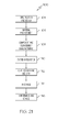
- Example 20 relates to method 500 for processing drilling location 148 in confined area 154 of workpiece 102 along drilling axis A using end effector 104.
- Method 500 comprises positioning end effector 104 relative to drilling location 148 of workpiece 102 (block 202) and clamping workpiece 102 between clamp 108 of end effector 104 and pressure foot 106 of end effector 104 (block 204).
- Pressure foot 106 supports clamp 108 movable relative to pressure foot 106.
- Method 500 further comprises drilling workpiece 102 with flat angle drill 110 of end effector 104 (block 206).
- clamping workpiece 102 between clamp 108 and the pressure foot 106 comprises exerting action force F 3 upon workpiece 102 by contacting workpiece 102 with clamp 108 biased toward workpiece 102 in a first direction (block 208), and exerting reaction force F 4 , equal and opposite to action force F 3 , upon workpiece 102 by contacting workpiece 102 with pressure foot 106 biased toward workpiece 102 in a second direction opposite to the first direction (block 210).
- method 500 further comprises avoiding obstruction 150 proximate drilling location 148 with frame 122 of clamp 108 when exerting action force F 3 upon workpiece 102 by spacing second arm member 172 of frame 122 from obstruction 150 using extension member 174 coupled to second arm member 172 (block 212).
- clamping workpiece 102 between clamp 108 and pressure foot 106 further comprises biasing pressure foot 106, supporting clamp 108, with force F 5 along drilling axis A (block 214).
- Force F 5 is directionally opposite to a gravitational force corresponding to a weight sum of spindle 118 of end effector 104, translation platform 182 of end effector 104, pressure foot 106, drill bracket 120 of end effector 104, flat angle drill 110, and clamp 108.
- Clamping workpiece 102 between clamp 108 and pressure foot 106 further comprises biasing clamp 108 toward workpiece 102 with force F 6 (block 216).
- Force F 6 has magnitude M 6 greater than an absolute value of a difference between magnitude M 5 of force F 5 and magnitude Mg of the gravitational force corresponding to the weight sum of spindle 118, translation platform 182, pressure foot 106, drill bracket 120, flat angle drill 110, and clamp 108.
- the difference between magnitude M 6 and magnitude M 5 is equal to magnitude M 4 of force F 4 .
- example 24 of the present disclosure.
- magnitude M5 is greater than magnitude Mg.
- example 25 of the present disclosure.
- magnitude M5 is less than magnitude Mg.
- method 500 further comprises accessing confined area 154 with flat angle drill 110, and aligning drilling axis A of flat angle drill 110 with drilling location 148 (block 218).
- method 500 further comprises opposing action force F 1 , transmitted to flat angle drill 110 along drilling axis A during the processing of drilling location 148, with reaction force F 2 produced by drill brace 128 of end effector 104.
- Reaction force F2 is equal and opposite to action force F1 (block 222).
- illustrative method 1100 may include specification and design block 1104 of aircraft 1102 and material procurement block 1106.
- component and subassembly manufacturing block 1108 and system integration block 1110 of aircraft 1102 may take place. Thereafter, aircraft 1102 may go through certification and delivery block 1112 to be placed in service block 1114. While in service, aircraft 1102 may be scheduled for routine maintenance and service block 1116. Routine maintenance and service may include modification, reconfiguration, refurbishment, etc. of one or more systems of aircraft 1102.
- a system integrator may include, without limitation, any number of aircraft manufacturers and major-system subcontractors; a third party may include, without limitation, any number of vendors, subcontractors, and suppliers; and an operator may be an airline, leasing company, military entity, service organization, and so on.
- aircraft 1102 produced by illustrative method 1100 may include airframe 1118 with a plurality of high-level systems 1120 and interior 1122.
- high-level systems 1120 include one or more of propulsion system 1124, electrical system 1126, hydraulic system 1128, and environmental system 1130. Any number of other systems may be included.
- Apparatus and methods shown or described herein may be employed during any one or more of the stages of the manufacturing and service method 1100.
- components or subassemblies corresponding to component and subassembly manufacturing 1108 may be fabricated or manufactured in a manner similar to components or subassemblies produced while aircraft 1102 is in service.
- one or more examples of the apparatus, method, or combination thereof may be utilized during production stages 1108 and 1110, for example, by substantially expediting assembly of or reducing the cost of aircraft 1102.
- one or more examples of the apparatus or method realizations, or a combination thereof may be utilized, for example and without limitation, while aircraft 1102 is in service, e.g., maintenance and service stage block 1116.
Landscapes
- Engineering & Computer Science (AREA)
- Mechanical Engineering (AREA)
- Robotics (AREA)
- Drilling And Boring (AREA)
- Manufacturing & Machinery (AREA)
- Transportation (AREA)
- Aviation & Aerospace Engineering (AREA)
- Manipulator (AREA)
- Processing Of Stones Or Stones Resemblance Materials (AREA)
- Earth Drilling (AREA)
- Perforating, Stamping-Out Or Severing By Means Other Than Cutting (AREA)
Applications Claiming Priority (1)
| Application Number | Priority Date | Filing Date | Title |
|---|---|---|---|
| US14/482,944 US9616503B2 (en) | 2014-09-10 | 2014-09-10 | Apparatuses and methods for processing a confined area of a workpiece |
Publications (2)
| Publication Number | Publication Date |
|---|---|
| EP2995402A1 true EP2995402A1 (fr) | 2016-03-16 |
| EP2995402B1 EP2995402B1 (fr) | 2024-08-07 |
Family
ID=54065761
Family Applications (1)
| Application Number | Title | Priority Date | Filing Date |
|---|---|---|---|
| EP15184071.7A Active EP2995402B1 (fr) | 2014-09-10 | 2015-09-07 | Appareil et procédé de traitement d'une zone confinée d'une pièce à usiner |
Country Status (6)
| Country | Link |
|---|---|
| US (2) | US9616503B2 (fr) |
| EP (1) | EP2995402B1 (fr) |
| JP (1) | JP6556560B2 (fr) |
| KR (1) | KR102368247B1 (fr) |
| CN (1) | CN105415077B (fr) |
| BR (1) | BR102015020619B1 (fr) |
Cited By (4)
| Publication number | Priority date | Publication date | Assignee | Title |
|---|---|---|---|---|
| CN109396496A (zh) * | 2018-12-12 | 2019-03-01 | 中国航空制造技术研究院 | 一种用于曲面类表面自动钻锪的锪窝深度控制方法 |
| IT201900001649A1 (it) * | 2019-02-05 | 2020-08-05 | Bb S P A | Macchina e metodo per la lavorazione di elementi concavi |
| EP3904219A1 (fr) * | 2020-04-30 | 2021-11-03 | Airbus Operations Limited | Pince automatisée |
| GB2627486A (en) * | 2023-02-24 | 2024-08-28 | Airbus Operations Ltd | Automated clamp |
Families Citing this family (20)
| Publication number | Priority date | Publication date | Assignee | Title |
|---|---|---|---|---|
| GB2512059B (en) * | 2013-03-18 | 2016-08-31 | Rolls Royce Plc | An independently moveable machine tool |
| US10427254B2 (en) | 2014-04-30 | 2019-10-01 | The Boeing Company | Flexible manufacturing for aircraft structures |
| US10118714B2 (en) * | 2014-04-30 | 2018-11-06 | The Boeing Company | System and method for positioning an automated assembly tool relative to a structure |
| US10000298B2 (en) | 2014-04-30 | 2018-06-19 | The Boeing Company | Metrology system for positioning assemblies |
| US10017277B2 (en) | 2014-04-30 | 2018-07-10 | The Boeing Company | Apparatus, system, and method for supporting a wing assembly |
| CN106270651A (zh) * | 2016-10-19 | 2017-01-04 | 陈明 | 一种机械传动装置加工制造用打孔设备 |
| CN108248889A (zh) * | 2016-12-28 | 2018-07-06 | 北京卓翼智能科技有限公司 | 用于折叠系留无人机机臂的转台装置 |
| US20190076932A1 (en) * | 2017-09-14 | 2019-03-14 | Spirit Aerosystems, Inc. | Apparatus and method for minimizing elongation in drilled holes |
| EP3466576B1 (fr) * | 2017-10-04 | 2020-03-18 | Airbus Operations, S.L. | Machine de perçage automatique permettant de percer en une fois au moins deux orifices d'une structure de traverse |
| DE102017127873B4 (de) * | 2017-11-24 | 2024-08-01 | Festool Gmbh | Führungsschablone |
| JP7265842B2 (ja) * | 2018-06-15 | 2023-04-27 | 株式会社北川鉄工所 | エンドエフェクタ及びワーク加工方法 |
| CN109607213B (zh) * | 2018-11-30 | 2021-02-02 | 成都信息工程大学 | 一种旋转式泡棉拆垛与信息喷印设备 |
| CN110842242A (zh) * | 2019-11-26 | 2020-02-28 | 湖南大学 | 适用于大型构件的镗孔加工设备 |
| JP7717810B2 (ja) * | 2021-02-01 | 2025-08-04 | アーベーベー・シュバイツ・アーゲー | 機械部品を機械加工するためのアセンブリ及び装置 |
| DE102021109904A1 (de) * | 2021-04-20 | 2022-10-20 | J. Schmalz Gmbh | Handhabungsvorrichtung mit definierter Ruhekonfiguration |
| US11813655B2 (en) | 2021-05-20 | 2023-11-14 | Kuka Systems North America Llc | Apparatus and methods for forming attachment pads |
| CN115945716A (zh) * | 2022-11-28 | 2023-04-11 | 南方海洋科学与工程广东省实验室(广州) | 一种基于rov的深海打捞钻孔装置及其使用方法 |
| GB2627511B (en) * | 2023-02-24 | 2025-05-07 | Airbus Operations Ltd | Self aligning system |
| GB2627488A (en) * | 2023-02-24 | 2024-08-28 | Airbus Operations Ltd | Automated clamp |
| CN115990892B (zh) * | 2023-03-24 | 2023-06-20 | 中航西安飞机工业集团股份有限公司 | 一种面向大型翼面类骨架的双机器人协同装配系统及方法 |
Citations (2)
| Publication number | Priority date | Publication date | Assignee | Title |
|---|---|---|---|---|
| US20080277953A1 (en) * | 2007-05-11 | 2008-11-13 | The Boeing Company | Robotic End Effector and Clamping Method |
| US20120138323A1 (en) * | 2009-08-07 | 2012-06-07 | The University Of Sheffield | Remote confined-space machining, and positioning and securing arrangement |
Family Cites Families (42)
| Publication number | Priority date | Publication date | Assignee | Title |
|---|---|---|---|---|
| US596471A (en) * | 1898-01-04 | Automatic overhead joist-boring machine | ||
| US2598106A (en) * | 1949-10-04 | 1952-05-27 | Cons Vultee Aircraft Corp | Drilling attachment for riveting machines |
| US2909949A (en) * | 1958-05-02 | 1959-10-27 | James C Winslow | Power drill with work holding device and spacing means |
| US3060769A (en) * | 1960-08-19 | 1962-10-30 | Merle J Heider | Portable self-drilling device |
| US3238624A (en) * | 1962-03-13 | 1966-03-08 | Melpar Inc | Printed circuit layout machine |
| US3162091A (en) * | 1963-06-03 | 1964-12-22 | K F Products Inc | Attachment for milling machines |
| US3260138A (en) * | 1964-06-18 | 1966-07-12 | Avco Corp | Attachment for a hand drill or the like |
| US3526158A (en) * | 1968-07-10 | 1970-09-01 | Omark Winslow Co | Two-speed power taper drill |
| US3518901A (en) * | 1968-07-22 | 1970-07-07 | Howald C Wright | Portable heavy duty offset drilling attachment |
| US4046263A (en) * | 1976-07-29 | 1977-09-06 | General Motors Corporation | Tool changing apparatus for a multi-axis manipulator |
| US4621398A (en) * | 1982-12-06 | 1986-11-11 | Rockwell International Corporation | Automaton tool mounting system |
| US4512709A (en) * | 1983-07-25 | 1985-04-23 | Cincinnati Milacron Inc. | Robot toolchanger system |
| US4601618A (en) * | 1985-02-27 | 1986-07-22 | The Boeing Company | Pilot hole locator and drill guide and method |
| US4679969A (en) * | 1986-04-07 | 1987-07-14 | Rockwell International Corporation | Positive feed drill clamp system |
| JPS62181350U (fr) * | 1986-05-12 | 1987-11-17 | ||
| US4948308A (en) * | 1988-05-02 | 1990-08-14 | Grumman Aerospace Corporation | Automated limited access drilling system |
| US4890962A (en) * | 1989-02-16 | 1990-01-02 | The Boeing Company | Portable positive feed drill |
| US4955119A (en) * | 1989-07-11 | 1990-09-11 | Imta | Multi-task end effector for robotic machining center |
| US5213454A (en) * | 1990-12-21 | 1993-05-25 | The Boeing Company | Apparatus for chip vacuum, mist lubrication and coil cooling |
| US5169047A (en) * | 1991-10-30 | 1992-12-08 | Endres Thomas E | Compact rivet attachment apparatus |
| US5283982A (en) * | 1992-04-01 | 1994-02-08 | Ltv Aerospace And Defense Company | Complex contour milling machine |
| US5779609A (en) * | 1996-01-16 | 1998-07-14 | Applied Robotics, Inc. | Integrated stud welding robotic tool changing system |
| US5888032A (en) * | 1996-09-13 | 1999-03-30 | Cooper Technologies Company | Paddle fitting tool |
| DE19639122A1 (de) * | 1996-09-24 | 1998-04-02 | Daimler Benz Aerospace Airbus | Vorrichtung zum Klemmen und Bohren |
| US5771551A (en) * | 1997-03-13 | 1998-06-30 | Aos Holding Company | Tool for punching and riveting including a combination cylinder |
| US6276050B1 (en) * | 1998-07-20 | 2001-08-21 | Emhart Inc. | Riveting system and process for forming a riveted joint |
| US6514018B2 (en) | 2001-03-22 | 2003-02-04 | The Boeing Company | Pneumatic drilling end effector |
| US7258512B2 (en) * | 2003-11-21 | 2007-08-21 | The Boeing Company | Drill clamp and method |
| CN2675308Y (zh) * | 2004-02-26 | 2005-02-02 | 总格实业股份有限公司 | 钻孔机的压力脚 |
| JP4603853B2 (ja) * | 2004-10-27 | 2010-12-22 | 株式会社Mstコーポレーション | 工具ホルダ |
| US20080027795A1 (en) * | 2006-07-27 | 2008-01-31 | Jennifer Medlin | Methods and systems for providing dynamic feedback to customers using transactional accounts for purchases |
| ITTO20070395A1 (it) * | 2007-06-06 | 2008-12-07 | Bruno Bisiach | Metodo di controllo di una macchina trapanatrice ed apparato che realizza detto metodo. |
| CN201111454Y (zh) * | 2007-10-19 | 2008-09-10 | 台湾泷泽科技股份有限公司 | 改良的印刷电路板钻孔机的主轴升降机构 |
| JP2010260139A (ja) * | 2009-05-08 | 2010-11-18 | Ntn Corp | 遠隔操作型加工ロボット |
| US8496416B1 (en) * | 2009-05-21 | 2013-07-30 | The Boeing Company | Method and apparatus for drilling operations |
| DE102009054604B4 (de) * | 2009-12-14 | 2012-09-20 | Frimo Group Gmbh | Verfahren und Vorrichtung zum teilweisen Durchtrennen eines Werkstücks |
| US9199351B2 (en) * | 2011-05-09 | 2015-12-01 | The Boeing Company | Drilling machine having hole measurement capability |
| DE202011052431U1 (de) * | 2011-12-22 | 2013-03-25 | Kuka Systems Gmbh | Bearbeitungswerkzeug |
| DE102012103548A1 (de) * | 2012-04-23 | 2013-10-24 | IBG-Automation GmbH | Verfahren und Vorrichtung zum Ausrichten eines Werkzeugs sowie Bearbeitungsstation und Messeinrichtung |
| US9168592B1 (en) * | 2012-08-14 | 2015-10-27 | The Boeing Company | Limited vertical access drilling machine |
| FR3001645B1 (fr) * | 2013-02-06 | 2015-05-15 | Aircelle Sa | Tete de percage acoustique |
| ES2659201T3 (es) * | 2013-07-09 | 2018-03-14 | Nihon Shoryoku Kikai Co., Ltd. | Aparato de mecanización |
-
2014
- 2014-09-10 US US14/482,944 patent/US9616503B2/en active Active
-
2015
- 2015-08-11 CN CN201510490060.0A patent/CN105415077B/zh active Active
- 2015-08-19 KR KR1020150116412A patent/KR102368247B1/ko active Active
- 2015-08-26 BR BR102015020619-4A patent/BR102015020619B1/pt active IP Right Grant
- 2015-08-28 JP JP2015169000A patent/JP6556560B2/ja active Active
- 2015-09-07 EP EP15184071.7A patent/EP2995402B1/fr active Active
-
2017
- 2017-02-01 US US15/421,904 patent/US10335865B2/en active Active
Patent Citations (2)
| Publication number | Priority date | Publication date | Assignee | Title |
|---|---|---|---|---|
| US20080277953A1 (en) * | 2007-05-11 | 2008-11-13 | The Boeing Company | Robotic End Effector and Clamping Method |
| US20120138323A1 (en) * | 2009-08-07 | 2012-06-07 | The University Of Sheffield | Remote confined-space machining, and positioning and securing arrangement |
Cited By (7)
| Publication number | Priority date | Publication date | Assignee | Title |
|---|---|---|---|---|
| CN109396496A (zh) * | 2018-12-12 | 2019-03-01 | 中国航空制造技术研究院 | 一种用于曲面类表面自动钻锪的锪窝深度控制方法 |
| IT201900001649A1 (it) * | 2019-02-05 | 2020-08-05 | Bb S P A | Macchina e metodo per la lavorazione di elementi concavi |
| EP3693113A1 (fr) * | 2019-02-05 | 2020-08-12 | BB S.p.A. | Machine et procédé d'usinage d'éléments concaves |
| EP3904219A1 (fr) * | 2020-04-30 | 2021-11-03 | Airbus Operations Limited | Pince automatisée |
| GB2594503A (en) * | 2020-04-30 | 2021-11-03 | Airbus Operations Ltd | Automated clamp |
| US12351341B2 (en) | 2020-04-30 | 2025-07-08 | Airbus Operations Limited | Automated clamp |
| GB2627486A (en) * | 2023-02-24 | 2024-08-28 | Airbus Operations Ltd | Automated clamp |
Also Published As
| Publication number | Publication date |
|---|---|
| CN105415077B (zh) | 2019-05-10 |
| US9616503B2 (en) | 2017-04-11 |
| KR102368247B1 (ko) | 2022-02-25 |
| US10335865B2 (en) | 2019-07-02 |
| US20170197253A1 (en) | 2017-07-13 |
| EP2995402B1 (fr) | 2024-08-07 |
| BR102015020619A2 (pt) | 2016-10-04 |
| BR102015020619B1 (pt) | 2023-01-31 |
| US20160067792A1 (en) | 2016-03-10 |
| KR20160030441A (ko) | 2016-03-18 |
| JP6556560B2 (ja) | 2019-08-07 |
| CN105415077A (zh) | 2016-03-23 |
| JP2016055425A (ja) | 2016-04-21 |
Similar Documents
| Publication | Publication Date | Title |
|---|---|---|
| US10335865B2 (en) | Methods for processing a confined area of a workpiece | |
| US9840010B2 (en) | Tool changer | |
| CA2927161C (fr) | Systeme robotique et effecteur d'extremite de forage pour systeme robotique | |
| JP7194175B2 (ja) | シャフトを自動的に交換する方法およびシステム | |
| US9987714B2 (en) | Automated installation of frangible elements | |
| US10315281B2 (en) | Reconfigurable interface assembly, adaptable assembly line work-piece processor, and method | |
| US9725190B2 (en) | Aircraft engine inlet assembly apparatus | |
| US20160039093A1 (en) | Low-impedance articulated device and method for assisting a manual assembly task | |
| US8496416B1 (en) | Method and apparatus for drilling operations | |
| US9283658B2 (en) | Self-centering clamp | |
| CN110076358A (zh) | 机床 | |
| US20200094421A1 (en) | Robot unit | |
| WO2015097102A1 (fr) | Procédé de montage automatisé sur un poste de travail de montage, et poste de travail de montage automatisé associé | |
| CN115870968A (zh) | 用于更换臂端工具的系统和方法 | |
| WO2011062696A1 (fr) | Système d'assemblage déterminant pour objets de fabrication | |
| GB2473191A (en) | Wall Mounted Robotic Arm and Position Sensing System | |
| US20170203370A1 (en) | Apparatuses and methods for tool height setting | |
| KR20230006512A (ko) | 로봇에 기계 공구들을 부착하기 위한 신속한 클램핑 시스템 | |
| KR20230111243A (ko) | 기계 부품을 가공하기 위한 조립체 및 장치 | |
| JP2024037712A (ja) | 処理中の部品加工の向きの変更/インデックス | |
| KR20220164738A (ko) | 부품들의 자동화 조립을 위한 시스템 및 방법 | |
| WO2001058627A1 (fr) | Ensemble porte-outil | |
| JP2024087766A (ja) | ワークピースの自動処理のためのシステム及び方法 | |
| CN114603541A (zh) | 一种模块化可移动机器人 | |
| Gaponov et al. | Telerobot System for Biocell Manipulation |
Legal Events
| Date | Code | Title | Description |
|---|---|---|---|
| PUAI | Public reference made under article 153(3) epc to a published international application that has entered the european phase |
Free format text: ORIGINAL CODE: 0009012 |
|
| AK | Designated contracting states |
Kind code of ref document: A1 Designated state(s): AL AT BE BG CH CY CZ DE DK EE ES FI FR GB GR HR HU IE IS IT LI LT LU LV MC MK MT NL NO PL PT RO RS SE SI SK SM TR |
|
| AX | Request for extension of the european patent |
Extension state: BA ME |
|
| 17P | Request for examination filed |
Effective date: 20160414 |
|
| RBV | Designated contracting states (corrected) |
Designated state(s): AL AT BE BG CH CY CZ DE DK EE ES FI FR GB GR HR HU IE IS IT LI LT LU LV MC MK MT NL NO PL PT RO RS SE SI SK SM TR |
|
| STAA | Information on the status of an ep patent application or granted ep patent |
Free format text: STATUS: EXAMINATION IS IN PROGRESS |
|
| 17Q | First examination report despatched |
Effective date: 20210303 |
|
| RAP3 | Party data changed (applicant data changed or rights of an application transferred) |
Owner name: THE BOEING COMPANY |
|
| GRAP | Despatch of communication of intention to grant a patent |
Free format text: ORIGINAL CODE: EPIDOSNIGR1 |
|
| STAA | Information on the status of an ep patent application or granted ep patent |
Free format text: STATUS: GRANT OF PATENT IS INTENDED |
|
| RIC1 | Information provided on ipc code assigned before grant |
Ipc: B25J 15/00 20060101ALI20230922BHEP Ipc: B25J 11/00 20060101ALI20230922BHEP Ipc: B23Q 5/04 20060101ALI20230922BHEP Ipc: B23B 41/00 20060101AFI20230922BHEP |
|
| INTG | Intention to grant announced |
Effective date: 20231020 |
|
| P01 | Opt-out of the competence of the unified patent court (upc) registered |
Effective date: 20231101 |
|
| GRAJ | Information related to disapproval of communication of intention to grant by the applicant or resumption of examination proceedings by the epo deleted |
Free format text: ORIGINAL CODE: EPIDOSDIGR1 |
|
| STAA | Information on the status of an ep patent application or granted ep patent |
Free format text: STATUS: EXAMINATION IS IN PROGRESS |
|
| INTC | Intention to grant announced (deleted) | ||
| GRAP | Despatch of communication of intention to grant a patent |
Free format text: ORIGINAL CODE: EPIDOSNIGR1 |
|
| STAA | Information on the status of an ep patent application or granted ep patent |
Free format text: STATUS: GRANT OF PATENT IS INTENDED |
|
| INTG | Intention to grant announced |
Effective date: 20240320 |
|
| GRAS | Grant fee paid |
Free format text: ORIGINAL CODE: EPIDOSNIGR3 |
|
| GRAA | (expected) grant |
Free format text: ORIGINAL CODE: 0009210 |
|
| STAA | Information on the status of an ep patent application or granted ep patent |
Free format text: STATUS: THE PATENT HAS BEEN GRANTED |
|
| AK | Designated contracting states |
Kind code of ref document: B1 Designated state(s): AL AT BE BG CH CY CZ DE DK EE ES FI FR GB GR HR HU IE IS IT LI LT LU LV MC MK MT NL NO PL PT RO RS SE SI SK SM TR |
|
| REG | Reference to a national code |
Ref country code: GB Ref legal event code: FG4D |
|
| REG | Reference to a national code |
Ref country code: CH Ref legal event code: EP |
|
| REG | Reference to a national code |
Ref country code: IE Ref legal event code: FG4D |
|
| REG | Reference to a national code |
Ref country code: DE Ref legal event code: R096 Ref document number: 602015089432 Country of ref document: DE |
|
| REG | Reference to a national code |
Ref country code: LT Ref legal event code: MG9D |
|
| REG | Reference to a national code |
Ref country code: NL Ref legal event code: MP Effective date: 20240807 |
|
| PG25 | Lapsed in a contracting state [announced via postgrant information from national office to epo] |
Ref country code: NO Free format text: LAPSE BECAUSE OF FAILURE TO SUBMIT A TRANSLATION OF THE DESCRIPTION OR TO PAY THE FEE WITHIN THE PRESCRIBED TIME-LIMIT Effective date: 20241107 |
|
| REG | Reference to a national code |
Ref country code: AT Ref legal event code: MK05 Ref document number: 1710402 Country of ref document: AT Kind code of ref document: T Effective date: 20240807 |
|
| PG25 | Lapsed in a contracting state [announced via postgrant information from national office to epo] |
Ref country code: FI Free format text: LAPSE BECAUSE OF FAILURE TO SUBMIT A TRANSLATION OF THE DESCRIPTION OR TO PAY THE FEE WITHIN THE PRESCRIBED TIME-LIMIT Effective date: 20240807 Ref country code: NL Free format text: LAPSE BECAUSE OF FAILURE TO SUBMIT A TRANSLATION OF THE DESCRIPTION OR TO PAY THE FEE WITHIN THE PRESCRIBED TIME-LIMIT Effective date: 20240807 Ref country code: PT Free format text: LAPSE BECAUSE OF FAILURE TO SUBMIT A TRANSLATION OF THE DESCRIPTION OR TO PAY THE FEE WITHIN THE PRESCRIBED TIME-LIMIT Effective date: 20241209 Ref country code: GR Free format text: LAPSE BECAUSE OF FAILURE TO SUBMIT A TRANSLATION OF THE DESCRIPTION OR TO PAY THE FEE WITHIN THE PRESCRIBED TIME-LIMIT Effective date: 20241108 Ref country code: PL Free format text: LAPSE BECAUSE OF FAILURE TO SUBMIT A TRANSLATION OF THE DESCRIPTION OR TO PAY THE FEE WITHIN THE PRESCRIBED TIME-LIMIT Effective date: 20240807 |
|
| PG25 | Lapsed in a contracting state [announced via postgrant information from national office to epo] |
Ref country code: BG Free format text: LAPSE BECAUSE OF FAILURE TO SUBMIT A TRANSLATION OF THE DESCRIPTION OR TO PAY THE FEE WITHIN THE PRESCRIBED TIME-LIMIT Effective date: 20240807 |
|
| PG25 | Lapsed in a contracting state [announced via postgrant information from national office to epo] |
Ref country code: LV Free format text: LAPSE BECAUSE OF FAILURE TO SUBMIT A TRANSLATION OF THE DESCRIPTION OR TO PAY THE FEE WITHIN THE PRESCRIBED TIME-LIMIT Effective date: 20240807 |
|
| PG25 | Lapsed in a contracting state [announced via postgrant information from national office to epo] |
Ref country code: IS Free format text: LAPSE BECAUSE OF FAILURE TO SUBMIT A TRANSLATION OF THE DESCRIPTION OR TO PAY THE FEE WITHIN THE PRESCRIBED TIME-LIMIT Effective date: 20241207 Ref country code: AT Free format text: LAPSE BECAUSE OF FAILURE TO SUBMIT A TRANSLATION OF THE DESCRIPTION OR TO PAY THE FEE WITHIN THE PRESCRIBED TIME-LIMIT Effective date: 20240807 |
|
| PG25 | Lapsed in a contracting state [announced via postgrant information from national office to epo] |
Ref country code: HR Free format text: LAPSE BECAUSE OF FAILURE TO SUBMIT A TRANSLATION OF THE DESCRIPTION OR TO PAY THE FEE WITHIN THE PRESCRIBED TIME-LIMIT Effective date: 20240807 |
|
| PG25 | Lapsed in a contracting state [announced via postgrant information from national office to epo] |
Ref country code: RS Free format text: LAPSE BECAUSE OF FAILURE TO SUBMIT A TRANSLATION OF THE DESCRIPTION OR TO PAY THE FEE WITHIN THE PRESCRIBED TIME-LIMIT Effective date: 20241107 Ref country code: ES Free format text: LAPSE BECAUSE OF FAILURE TO SUBMIT A TRANSLATION OF THE DESCRIPTION OR TO PAY THE FEE WITHIN THE PRESCRIBED TIME-LIMIT Effective date: 20240807 |
|
| PG25 | Lapsed in a contracting state [announced via postgrant information from national office to epo] |
Ref country code: RS Free format text: LAPSE BECAUSE OF FAILURE TO SUBMIT A TRANSLATION OF THE DESCRIPTION OR TO PAY THE FEE WITHIN THE PRESCRIBED TIME-LIMIT Effective date: 20241107 Ref country code: PT Free format text: LAPSE BECAUSE OF FAILURE TO SUBMIT A TRANSLATION OF THE DESCRIPTION OR TO PAY THE FEE WITHIN THE PRESCRIBED TIME-LIMIT Effective date: 20241209 Ref country code: PL Free format text: LAPSE BECAUSE OF FAILURE TO SUBMIT A TRANSLATION OF THE DESCRIPTION OR TO PAY THE FEE WITHIN THE PRESCRIBED TIME-LIMIT Effective date: 20240807 Ref country code: NO Free format text: LAPSE BECAUSE OF FAILURE TO SUBMIT A TRANSLATION OF THE DESCRIPTION OR TO PAY THE FEE WITHIN THE PRESCRIBED TIME-LIMIT Effective date: 20241107 Ref country code: NL Free format text: LAPSE BECAUSE OF FAILURE TO SUBMIT A TRANSLATION OF THE DESCRIPTION OR TO PAY THE FEE WITHIN THE PRESCRIBED TIME-LIMIT Effective date: 20240807 Ref country code: LV Free format text: LAPSE BECAUSE OF FAILURE TO SUBMIT A TRANSLATION OF THE DESCRIPTION OR TO PAY THE FEE WITHIN THE PRESCRIBED TIME-LIMIT Effective date: 20240807 Ref country code: IS Free format text: LAPSE BECAUSE OF FAILURE TO SUBMIT A TRANSLATION OF THE DESCRIPTION OR TO PAY THE FEE WITHIN THE PRESCRIBED TIME-LIMIT Effective date: 20241207 Ref country code: HR Free format text: LAPSE BECAUSE OF FAILURE TO SUBMIT A TRANSLATION OF THE DESCRIPTION OR TO PAY THE FEE WITHIN THE PRESCRIBED TIME-LIMIT Effective date: 20240807 Ref country code: GR Free format text: LAPSE BECAUSE OF FAILURE TO SUBMIT A TRANSLATION OF THE DESCRIPTION OR TO PAY THE FEE WITHIN THE PRESCRIBED TIME-LIMIT Effective date: 20241108 Ref country code: FI Free format text: LAPSE BECAUSE OF FAILURE TO SUBMIT A TRANSLATION OF THE DESCRIPTION OR TO PAY THE FEE WITHIN THE PRESCRIBED TIME-LIMIT Effective date: 20240807 Ref country code: ES Free format text: LAPSE BECAUSE OF FAILURE TO SUBMIT A TRANSLATION OF THE DESCRIPTION OR TO PAY THE FEE WITHIN THE PRESCRIBED TIME-LIMIT Effective date: 20240807 Ref country code: BG Free format text: LAPSE BECAUSE OF FAILURE TO SUBMIT A TRANSLATION OF THE DESCRIPTION OR TO PAY THE FEE WITHIN THE PRESCRIBED TIME-LIMIT Effective date: 20240807 Ref country code: AT Free format text: LAPSE BECAUSE OF FAILURE TO SUBMIT A TRANSLATION OF THE DESCRIPTION OR TO PAY THE FEE WITHIN THE PRESCRIBED TIME-LIMIT Effective date: 20240807 |
|
| PG25 | Lapsed in a contracting state [announced via postgrant information from national office to epo] |
Ref country code: RO Free format text: LAPSE BECAUSE OF FAILURE TO SUBMIT A TRANSLATION OF THE DESCRIPTION OR TO PAY THE FEE WITHIN THE PRESCRIBED TIME-LIMIT Effective date: 20240807 Ref country code: SM Free format text: LAPSE BECAUSE OF FAILURE TO SUBMIT A TRANSLATION OF THE DESCRIPTION OR TO PAY THE FEE WITHIN THE PRESCRIBED TIME-LIMIT Effective date: 20240807 Ref country code: DK Free format text: LAPSE BECAUSE OF FAILURE TO SUBMIT A TRANSLATION OF THE DESCRIPTION OR TO PAY THE FEE WITHIN THE PRESCRIBED TIME-LIMIT Effective date: 20240807 |
|
| PG25 | Lapsed in a contracting state [announced via postgrant information from national office to epo] |
Ref country code: EE Free format text: LAPSE BECAUSE OF FAILURE TO SUBMIT A TRANSLATION OF THE DESCRIPTION OR TO PAY THE FEE WITHIN THE PRESCRIBED TIME-LIMIT Effective date: 20240807 |
|
| PG25 | Lapsed in a contracting state [announced via postgrant information from national office to epo] |
Ref country code: CZ Free format text: LAPSE BECAUSE OF FAILURE TO SUBMIT A TRANSLATION OF THE DESCRIPTION OR TO PAY THE FEE WITHIN THE PRESCRIBED TIME-LIMIT Effective date: 20240807 |
|
| PG25 | Lapsed in a contracting state [announced via postgrant information from national office to epo] |
Ref country code: SK Free format text: LAPSE BECAUSE OF FAILURE TO SUBMIT A TRANSLATION OF THE DESCRIPTION OR TO PAY THE FEE WITHIN THE PRESCRIBED TIME-LIMIT Effective date: 20240807 |
|
| REG | Reference to a national code |
Ref country code: CH Ref legal event code: PL |
|
| REG | Reference to a national code |
Ref country code: DE Ref legal event code: R097 Ref document number: 602015089432 Country of ref document: DE |
|
| PG25 | Lapsed in a contracting state [announced via postgrant information from national office to epo] |
Ref country code: LU Free format text: LAPSE BECAUSE OF NON-PAYMENT OF DUE FEES Effective date: 20240907 |
|
| PLBE | No opposition filed within time limit |
Free format text: ORIGINAL CODE: 0009261 |
|
| STAA | Information on the status of an ep patent application or granted ep patent |
Free format text: STATUS: NO OPPOSITION FILED WITHIN TIME LIMIT |
|
| PG25 | Lapsed in a contracting state [announced via postgrant information from national office to epo] |
Ref country code: MC Free format text: LAPSE BECAUSE OF FAILURE TO SUBMIT A TRANSLATION OF THE DESCRIPTION OR TO PAY THE FEE WITHIN THE PRESCRIBED TIME-LIMIT Effective date: 20240807 |
|
| REG | Reference to a national code |
Ref country code: BE Ref legal event code: MM Effective date: 20240930 |
|
| PG25 | Lapsed in a contracting state [announced via postgrant information from national office to epo] |
Ref country code: BE Free format text: LAPSE BECAUSE OF NON-PAYMENT OF DUE FEES Effective date: 20240930 |
|
| 26N | No opposition filed |
Effective date: 20250508 |
|
| PG25 | Lapsed in a contracting state [announced via postgrant information from national office to epo] |
Ref country code: CH Free format text: LAPSE BECAUSE OF NON-PAYMENT OF DUE FEES Effective date: 20240930 |
|
| PG25 | Lapsed in a contracting state [announced via postgrant information from national office to epo] |
Ref country code: IE Free format text: LAPSE BECAUSE OF NON-PAYMENT OF DUE FEES Effective date: 20240907 |
|
| PG25 | Lapsed in a contracting state [announced via postgrant information from national office to epo] |
Ref country code: SE Free format text: LAPSE BECAUSE OF FAILURE TO SUBMIT A TRANSLATION OF THE DESCRIPTION OR TO PAY THE FEE WITHIN THE PRESCRIBED TIME-LIMIT Effective date: 20240807 |
|
| PGFP | Annual fee paid to national office [announced via postgrant information from national office to epo] |
Ref country code: DE Payment date: 20250929 Year of fee payment: 11 |
|
| PGFP | Annual fee paid to national office [announced via postgrant information from national office to epo] |
Ref country code: GB Payment date: 20250929 Year of fee payment: 11 |
|
| PGFP | Annual fee paid to national office [announced via postgrant information from national office to epo] |
Ref country code: FR Payment date: 20250925 Year of fee payment: 11 |
|
| PG25 | Lapsed in a contracting state [announced via postgrant information from national office to epo] |
Ref country code: IT Free format text: LAPSE BECAUSE OF NON-PAYMENT OF DUE FEES Effective date: 20240907 |
|
| PG25 | Lapsed in a contracting state [announced via postgrant information from national office to epo] |
Ref country code: CY Free format text: LAPSE BECAUSE OF FAILURE TO SUBMIT A TRANSLATION OF THE DESCRIPTION OR TO PAY THE FEE WITHIN THE PRESCRIBED TIME-LIMIT; INVALID AB INITIO Effective date: 20150907 |
|
| PG25 | Lapsed in a contracting state [announced via postgrant information from national office to epo] |
Ref country code: HU Free format text: LAPSE BECAUSE OF FAILURE TO SUBMIT A TRANSLATION OF THE DESCRIPTION OR TO PAY THE FEE WITHIN THE PRESCRIBED TIME-LIMIT; INVALID AB INITIO Effective date: 20150907 |
|
| PG25 | Lapsed in a contracting state [announced via postgrant information from national office to epo] |
Ref country code: IT Free format text: LAPSE BECAUSE OF NON-PAYMENT OF DUE FEES Effective date: 20240907 |
|
| PGFP | Annual fee paid to national office [announced via postgrant information from national office to epo] |
Ref country code: IT Payment date: 20250919 Year of fee payment: 11 |
|
| PGRI | Patent reinstated in contracting state [announced from national office to epo] |
Ref country code: IT Effective date: 20250131 |