EP2995403A1 - Perceuse alimentee par batterie - Google Patents
Perceuse alimentee par batterie Download PDFInfo
- Publication number
- EP2995403A1 EP2995403A1 EP14794249.4A EP14794249A EP2995403A1 EP 2995403 A1 EP2995403 A1 EP 2995403A1 EP 14794249 A EP14794249 A EP 14794249A EP 2995403 A1 EP2995403 A1 EP 2995403A1
- Authority
- EP
- European Patent Office
- Prior art keywords
- wall portion
- frame
- drilling
- battery
- drilling machine
- Prior art date
- Legal status (The legal status is an assumption and is not a legal conclusion. Google has not performed a legal analysis and makes no representation as to the accuracy of the status listed.)
- Granted
Links
Images


Classifications
-
- B—PERFORMING OPERATIONS; TRANSPORTING
- B23—MACHINE TOOLS; METAL-WORKING NOT OTHERWISE PROVIDED FOR
- B23B—TURNING; BORING
- B23B45/00—Hand-held or like portable drilling machines, e.g. drill guns; Equipment therefor
- B23B45/001—Housing of the drill, e.g. handgrip
-
- B—PERFORMING OPERATIONS; TRANSPORTING
- B23—MACHINE TOOLS; METAL-WORKING NOT OTHERWISE PROVIDED FOR
- B23B—TURNING; BORING
- B23B45/00—Hand-held or like portable drilling machines, e.g. drill guns; Equipment therefor
- B23B45/02—Hand-held or like portable drilling machines, e.g. drill guns; Equipment therefor driven by electric power
-
- B—PERFORMING OPERATIONS; TRANSPORTING
- B25—HAND TOOLS; PORTABLE POWER-DRIVEN TOOLS; MANIPULATORS
- B25H—WORKSHOP EQUIPMENT, e.g. FOR MARKING-OUT WORK; STORAGE MEANS FOR WORKSHOPS
- B25H1/00—Work benches; Portable stands or supports for positioning portable tools or work to be operated on thereby
- B25H1/0021—Stands, supports or guiding devices for positioning portable tools or for securing them to the work
- B25H1/0057—Devices for securing hand tools to the work
- B25H1/0064—Stands attached to the workpiece
- B25H1/0071—Stands attached to the workpiece by magnetic means
-
- B—PERFORMING OPERATIONS; TRANSPORTING
- B23—MACHINE TOOLS; METAL-WORKING NOT OTHERWISE PROVIDED FOR
- B23B—TURNING; BORING
- B23B2260/00—Details of constructional elements
- B23B2260/024—Batteries
Definitions
- the present invention relates to a portable drilling machine driven by a battery.
- Background Art :
- a portable drilling machine has a frame, a drilling drive unit having a motor for rotationally driving a drilling tool, e.g. a drill, and vertically movably attached to the frame, and a securing unit provided underneath the frame to removably and securely hold the drilling machine to a workpiece, as disclosed, for example, in Patent Literature 1.
- the frame has an interior space. In the interior space is disposed a drive control unit for controlling the motor of the drilling drive unit and so forth, together with electric wiring, etc.
- the frame is usually made of a metal casting in order to ensure sufficient strength, and this limits available configurations of the frame and increases the wall thickness of the frame, leading to an increase in the overall size and weight of the drilling machine.
- the use has been made of a battery to drive a drilling tool in order to improve the portability of drilling machines of the type described above.
- the battery is held in a battery receiving part provided in the frame. Accordingly, the frame formed as a casting correspondingly increases in size and weight.
- Patent Literature 1
- an object of the present invention is to provide a drilling machine using a battery and capable of being reduced in size and weight as compared with the above-described conventional drilling machines.
- the present invention provides a drilling machine including: a frame having a lower wall portion removably attached to a workpiece to be subjected to drilling and a front wall portion contiguous with the lower wall portion and extending upward from the lower wall portion to form an L-shape together with the lower wall portion; a drilling drive unit having a motor for rotationally driving a drilling tool, the drilling drive unit being attached to the front side of the front wall portion so as to be vertically movable along the front wall portion to bring the drilling tool toward and away from the workpiece, with the lower wall portion secured to the workpiece; and a battery housing prepared separately from the frame and attached to the frame to hold a battery as a power source for driving the motor at a position at the rear side of the front wall portion and at the upper side of the lower wall portion.
- the frame has sufficient strength to support a load generated during the drilling by the drilling tool.
- the frame supporting the drilling drive unit and having sufficient strength to support a load generated during the drilling by the drilling tool and the battery housing attached to the frame are formed as separate members, thereby allowing the mechanical strength of the battery housing to be reduced. Accordingly, the battery housing need not be made of a casting or the like as described above but can be formed of a resin material or the like. In addition, the degree of freedom for selecting a configuration increases, and the drilling machine can be made smaller in size and weight.
- an interior space for disposing a drive control circuit for controlling the motor may be formed between the frame and the battery housing.
- the battery housing may comprise a right-side part and a left-side part, which are attached to the frame individually.
- the laterally split structure of the battery housing allows an improvement in the operability for assembling the circuit, wiring, etc. into the battery housing.
- the drilling machine may further include a securing unit attached to the lower side of the lower wall portion to removably secure the lower wall portion to the workpiece.
- the securing unit may be an electromagnet type securing unit connected to the battery.
- the drilling machine may further include an electromagnet switch for activating the electromagnet type securing unit and a motor switch for starting the motor.
- the electromagnet switch and the motor switch may be provided on the different lateral sides, respectively, of the battery housing.
- the drive control circuit may be disposed parallel to the front wall portion or the lower wall portion of the frame in the interior space.
- the frame may be made of a metallic material
- the battery housing may be made of a resin material.
- the L-shaped frame supporting the drilling drive unit which is relatively heavy in weight and subjected to a large force from the drilling tool during drilling, is made of a metallic material to ensure sufficient strength, while the battery housing, which is not subjected to a very large force, is made of a resin material.
- a resin material to make the battery housing for holding the battery, it is possible to prevent short circuit due to contact of a connecting terminal of the battery with a metallic member and to also prevent wear of and damage to the battery when the battery, which is usually covered with a resin casing, is loaded into and unloaded from the battery housing.
- the frame may have a right-side rib provided between the respective right-side edges of the lower wall portion and the front wall portion, and a left-side rib provided between the respective left-side edges of the lower wall portion and the front wall portion.
- the battery housing may have an intermediate wall portion extending apart from and parallel to the front wall portion at the rear side of the front wall portion, and right- and left-side wall portions extending rearward from the right-and left-side edges, respectively, of the intermediate wall portion.
- the intermediate wall portion and the right- and left-side wall portions define a battery accommodating space for removably accommodating the battery.
- the battery accommodating space for accommodating the battery is located at a position rearwardly separate from the front wall portion to which the drilling drive unit is attached, and consequently, the drilling drive unit and the battery, which are relatively heavy in weight, are disposed at respective positions separate from each other in the longitudinal direction. Accordingly, the overall weight balance of the drilling machine is improved, so that the drilling machine becomes unlikely to fall down. In addition, the drilling machine can keep a stable position even during being carried. Further, because the motor and the battery, which are heating elements, are disposed away from each other, efficient heat dissipation and cooling can be carried out.
- the battery accommodating space may have a bottom wall portion sandwiched between the right- and left-side wall portions.
- the bottom wall portion may be sloped downward from the front toward the rear.
- the arrangement may be as follows.
- the housing has a right-side grip portion provided on the top of the right-side part, and a left-side grip portion provided on the top of the left-side part.
- the right-side grip portion and the left-side grip portion form a grip when the right-side part and the left-side part are attached to the frame.
- the right-side grip portion and the left-side grip portion are connected and secured to each other with a screw extending from the right-side grip portion to the left-side grip portion.
- the front side of the front wall portion of the frame may be provided with a dovetail groove
- the drilling drive unit may be provided with a slider slidingly engageable with the dovetail groove
- the provision of the dovetail groove directly on the front wall portion of the frame allows a reduction in parts count and a further downsizing of the drilling machine.
- the arrangement may be as follows.
- the drive control circuit is disposed at a lower position in the interior space.
- a circuit member connected to the drive control circuit through wiring is provided at an upper position in the interior space.
- the battery housing has a partition plate dividing the interior space into upper and lower parts at a position between the drive control circuit and the circuit member.
- the partition plate is provided with a vertical opening communicating between the upper and lower parts.
- the opening is provided with a seal member sealingly engaged with the opening.
- the wiring is routed through the opening and sealed from the partition plate by the seal member.
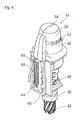
- a drilling machine 10 is a battery-operated portable drilling machine 10 having a body unit 12, a drilling drive unit 14 attached to the front side of the body unit 12 so as to vertically reciprocate relative to the body unit 12, a battery 16 loaded in the rear upper part of the body unit 12, and an electromagnet-type securing unit 18 attached to the lower side of the body unit 12 to securely hold the body unit 12 in a position for a drilling operation by the drilling machine 10.
- the drilling machine 10 is secured to a predetermined drilling operation position by the electromagnet-type securing unit 18.
- a drilling tool 44 attached to the lower end of the drilling drive unit 14 is driven to rotate by a motor 48, and a feed handle 66 attached to the body unit 12 is rotated to move the drilling drive unit 14 downward relative to the body unit 12 through a gear device comprising a rack 64 and a pinion 65, thereby drilling a workpiece with the drilling tool 44.
- the body unit 12 has, as shown in Fig. 3 , a structure comprising an L-shaped frame 20 and a battery housing 22.
- the frame 20 comprises a front wall portion 20-1 to which the drilling drive unit 14 is attached, and a lower wall portion 20-2 to which the electromagnet-type securing unit 18 is attached.
- the front wall portion 20-1 and the lower wall portion 20-2 form an L-shape.
- the battery housing 22 is attached to the frame 20 to removably hold the battery 16.
- the frame 20, to which the drilling drive unit 14 and the electromagnet-type securing unit 18 are attached directly and which is subjected to a relatively large force, is made of aluminum to ensure necessary and sufficient strength, while the battery housing 22, which is not subjected to such a large force, is made of a resin material to achieve a reduction in weight. Because the battery housing 22 is made of a resin material, no short circuit occurs even when a connecting terminal (not shown) of the battery 16 contacts the battery housing 22.
- the term "L-shaped frame" as used herein means to include any structure of frame 20 containing an L-shaped portion even if the overall configuration is not an L-shape, e.g. a frame structure in which a part of the lower wall portion 20-2 extends forward beyond the front wall portion 20-1 and which has therefore a non L-shape.
- the frame 20 has a right-side rib 20-3 provided between the respective right-side edges of the front wall portion 20-1 and the lower wall portion 20-2 and a left-side rib 20-4 provided between the respective left-side edges of the front wall portion 20-1 and the lower wall portion 20-2.
- the right- and left-side ribs 20-3 and 20-4 enhance the strength of the frame 20, which supports the drilling drive unit 14.
- a handle mounting hole 20-8 is formed between the upper end portions of the right- and left-side ribs 20-3 and 20-4 extending between a right side 20-10 and a left side 20-11.
- the handle mounting hole 20-8 is provided therein with a shaft 23-1 to which a feed handle 66 is attached, and a circular cylindrical gear mechanism part 23 containing a pinion 65 ( Figs. 3 and 7 ) for converting the rotation of the shaft caused by the feed handle 66 into vertical motion of the drilling drive unit 14.
- the battery housing 22 comprises a right-side part 22-1 and a left-side part 22-2, which are defined by splitting the battery housing 22 at the center thereof.
- the right-side part 22-1 and the left-side part 22-2 are attached to the frame 20 in such a manner as to sandwich the frame 20 therebetween from the right and left sides.
- an interior space 24 ( Fig. 3 ) is formed between the battery housing 22 and the frame 20.
- a drive control circuit 36 ( Fig. 4 ) is disposed at a position between the right- and left-side ribs 20-3 and 20-4 in parallel to the front wall portion 20-1.
- the drive control circuit 36 controls electric power supplied from the battery 16 to the motor 48 of the drilling drive unit 14 and to an electromagnet 18-1 in the electromagnet-type securing unit 18, as will be explained later. It should be noted that the drive control circuit 36 may be disposed on and parallel to the lower wall portion 20-2.
- the frame 20 is provided with engagement grooves 20-5 extending from the top 20-12 of the front wall portion 20-1 to the lower ends of the right and left sides 20-10 and 20-11, respectively.
- the lower wall portion 20-2 has an upper plate-shaped portion 20-2a and a lower block-shaped portion 20-2b integrally formed with the upper plate-shaped portion 20-2a.
- the battery housing 22 is provided with a front opening portion 22-4 for receiving the front wall portion 20-1 of the frame 20 and a lower opening portion 22-5 for receiving the lower wall portion 20-2 of the frame 20.
- the battery housing 22 is formed with an inwardly projecting edge portion 22-6 along the top and vertical edge of the front opening portion 22-4 and the edge of the lower opening portion 22-5.
- the projecting edge portion 22-6 is engaged with the associated engagement groove 20-5 of the frame and with the lower surface 20-6 of the edge of the upper plate-shaped portion 20-2a.
- the battery housing 22 is further formed with a projecting annular edge portion 22-8 to be engaged with the handle mounting hole 20-8 of the frame 20.
- the battery housing 22 is formed with engagement projecting portions 22-9 to be engaged with circular engagement recesses 20-9, respectively, formed on the right- and left-side ribs 20-3 and 20-4 of the frame 20.
- Each engagement projecting portion 22-9 comprises 6 projections arranged in a circle.
- the battery housing 22 has screw insertion holes 22-11 provided in each of right and left sides 22-14 and 22-15 ( Fig. 1 ) thereof. Screws 82 ( Fig. 1 ) are inserted through the screw insertion holes 22-11, respectively, and engaged with 4 threaded holes 21, respectively, provided in each of the right and left sides 20-10 and 20-11 of the frame 20, thereby securing the battery housing 22 to the frame 20.
- the battery housing 22 is secured to the frame 20 at a large number of points; therefore, stress concentration is less likely to occur even when a large force is applied to the battery housing 22, and the danger of the battery housing 22 being broken is reduced.
- a grip 26 provided on the top of the battery housing 22 comprises, as shown in Fig. 4 , a right-side grip portion 26-1 formed on the right-side part 22-1 of the battery housing 22 and a left-side grip portion 26-2 formed on the left-side part 22-2 of the battery housing 22.
- the right-side grip portion 26-1 and the left-side grip portion 26-2 form a grip 26 ( Fig. 1 ) when the right-side part 22-1 and the left-side part 22-2 are attached to the frame 20.
- the right-side grip portion 26-1 and the left-side grip portion 26-2 are connected and secured to each other by a screw 27 ( Fig. 2 ) extending from the right-side grip portion 26-1 to the left-side grip portion 26-2.
- the screw functions also as a reinforcing member to increase the strength of the grip 26.
- a battery accommodating space 28 for receiving the battery 16 is provided at the rear upper part of the battery housing 22.
- the battery 16 is removably loaded in the battery accommodating space 28.
- the battery accommodating space 28 is defined as a space surrounded by an intermediate wall portion 28-1 extending apart from and parallel to the front wall portion 20-1 of the frame 20 at the rear of the front wall portion 20-1, a bottom wall portion 28-2 contiguous with the intermediate wall portion 28-1, and a right-side wall portion 28-3 and a left-side wall portion 28-4 extending rearward from the right- and left-side edges, respectively, of the intermediate wall portion 28-1.
- the battery accommodating space 28 is open at the upper and rear sides thereof.
- the battery 16 is slidingly inserted into the battery accommodating space 28 from the open upper side toward the lower side, thereby being loaded into the battery accommodating space 28.
- the bottom wall portion 28-2 is slightly sloped downward from the front toward the rear, so that water entering the battery accommodating space 28 is discharged naturally.
- connecting terminals of the battery 16 face downward to prevent water or dust from easily entering the battery 16.
- a battery cover 30 is provided slidably in the front-back direction.
- the battery cover 30 projects rearward from the battery housing 22 to abut against an inclined cover engaging surface 16-1 ( Fig. 3 ) of the battery 16, thereby making the battery 16 unable to be removed from the battery housing 22.
- the battery cover 30 covers (although partially) the gap between the intermediate wall portion 28-1 of the battery housing 22 and the battery 16 from above. Therefore, machining swarf, water, etc. can be prevented from easily entering the terminal part of the battery 16.
- the battery cover 30 is pushed forward to retract into the battery housing 22, and then the battery 16 is pulled out upward.
- the battery cover 30 also prevents the battery 16 from becoming dislodged accidentally.
- the battery cover 30 has a downwardly projecting switch engaging projection 30-1 provided on a part thereof located in the battery housing 22.
- the switch engaging projection 30-1 pushes to turn on a limit switch 32 provided in the body unit 12.
- the switch engaging projection 30-1 turns off the limit switch 32.
- the limit switch 32 is connected to a drive control circuit 36 disposed in the interior space 24. The limit switch 32 is used to monitor whether or not the battery 16 is correctly loaded and whether or not the battery 16 is in a removable position.
- the loaded battery 16 is electrically connected to the drive control circuit 36 to supply electric power to the motor 48 and the electromagnet-type securing unit 18 through the drive control circuit 36.
- the electric power supplied from the battery 16 to the motor 48 and the electromagnet-type securing unit 18 is appropriately controlled by the drive control circuit 36.
- the interior space 24, which is formed between the battery housing 22 and the frame 20, has an upper interior space 24-1 located in an upper part of the interior space 24.
- An LED display circuit 34 is disposed in the upper interior space 24-1 in such a manner as to be visible from the outside of the battery housing 22.
- the LED display circuit 34 displays a status of the drilling machine 10 through an LED display 33 ( Fig. 1 ) on the top of the battery housing 22 according to a signal from the drive control circuit 36.
- the LED display circuit 34 has green, yellow and red LEDs to inform the operator about the remaining capacity of the battery 16 and the level of load on the motor 48 and to warn the operator about occurrence of abnormality by blink patterns of the LEDs.
- the above-described limit switch 32 is disposed underneath the LED display circuit 34.
- the drive control circuit 36, the LED display circuit 34 and the limit switch 32 are electrically connected to each other through wiring 35 covered with shrinkable tubing or the like.
- the battery housing 22 is provided with a partition plate 38 at a position between the drive control circuit 36, on the one hand, and, on the other, the LED display circuit 34 and the limit switch 32 to separate a lower interior space 24-2, where the drive control circuit 36 is disposed, from the upper interior space 24-1, where the LED display circuit 34 and the limit switch 32 are disposed.
- a right-side partition plate 38-1 provided in the right-side part 22-1 of the battery housing 22 and a left-side partition plate 38-2 provided in the left-side part 22-2 of the battery housing 22 face each other in such a manner as to form an L-shaped opening therebetween, and an L-shaped seal member 39 is attached so as to sealingly engage the opening.
- the L-shaped seal member 39 has a wiring insertion hole 39-1 formed in the center thereof, and the wiring 35 connected to the LED display circuit 34 and the limit switch 32 is passed through the wiring insertion hole 39-1 and thus sealed.
- the partition plate 38 is provided so as to slope downward from the rear toward the front.
- a drain port 80 is provided in a part of the front wall portion 20-1 of the frame 20 that is located in the upper interior space 24-1.
- the upper interior space 24-1 is not sealed from the outside because the upper interior space 24-1 slidably receives the battery cover 30, which projects to the outside of the battery housing 22. Therefore, there is a possibility that water, e.g. rainwater, may enter the upper interior space 24-1 from the outside.
- the above-described structure having the sloped partition plate 38 and the drain port 80 makes it possible to discharge water entering the upper interior space 24-1 to the outside from the drain port 80 without allowing the water to enter the lower interior space 24-2, in which the drive control circuit 36 is located.
- the upper surface of the upper plate-shaped portion 20-2a slopes downward from the front toward the rear, so that if water should enter the lower interior space 24-2, the water is discharged to the outside from a drain groove 20-13 provided at the rear end of the upper plate-shaped portion 20-2a.
- the drilling drive unit 14 attached to the front side of the front wall portion 20-1 of the frame 20 has an arbor 40 located at the lower side of the drilling drive unit 14.
- the arbor 40 is fitted with a drilling tool 44 such as a drill or an annular cutter.
- the arbor 40 is connected through a speed reducer 45 to a motor 48 provided in a motor cover 46 at the upper side of the drilling drive unit 14.
- the drilling tool 44 is driven to rotate by driving the motor 48.
- the motor cover 46 has a plurality of vent holes 52 provided in side surfaces 50 thereof to cool the motor 48 by air flowing in through the vent holes 52.
- vent holes 52 are provided not in a top surface 54 but in the side surfaces 50 .
- the left side of the drilling drive unit 14 is provided with a plug 56 serving as a cutting fluid filler port.
- a one-touch socket with hose is attached to the plug 56 to supply a cutting fluid to the drilling tool 44 during drilling.
- the front side of the front wall portion 20-1 of the frame 20 has vertically extending dovetail grooves 62 formed on the right and left sides thereof.
- the drilling drive unit 14 is, as shown in Fig. 8 , provided with a slider 63 having right-and left-side edges shaped to correspond to the dovetail grooves 62.
- the slider 63 is provided with a rack 64 ( Fig. 8 ), and the frame 20 is provided with a pinion 65 ( Fig. 7 ) to be engaged with the rack 64.
- the pinion 65 is rotated by manually rotating a feed handle 66 removably attached to an end of the shaft 23-1 projecting from the right side 20-10 ( Fig.
- the feed handle 66 can also be attached to an end of the shaft 23-1 projecting from the left side 20-11 of the frame 20.
- the feed handle 66 can be attached to either of the right and left sides of the frame 20 according to each particular situation.
- Wiring 68 extending from the motor 48 of the drilling drive unit 14 passes through a wiring insertion passage 69 ( Figs. 7 and 8 ) formed between one dovetail groove 62 and the slider 63, as shown in Fig. 3 , and leads into the interior space 24 of the body unit 12, in which the wiring 68 is connected to the drive control circuit 36.
- a wiring insertion passage 69 ( Figs. 7 and 8 ) formed between one dovetail groove 62 and the slider 63, as shown in Fig. 3 , and leads into the interior space 24 of the body unit 12, in which the wiring 68 is connected to the drive control circuit 36.
- the electromagnet-type securing unit 18 attached to the lower side of the body unit 12 is configured such that, when electric power is supplied to the electromagnet 18-1 therein, the electromagnet-type securing unit 18 generates a magnetic field and thus magnetically adheres to a magnetic material, e.g. iron, thereby securely holding the drilling machine 10.
- a position adjusting mechanism 58 is provided between the electromagnet-type securing unit 18 and the frame 20 to allow the position of the body unit 12 to be adjusted both longitudinally and laterally relative to the electromagnet-type securing unit 18 by turning a position adjusting handle 60 removably attached to the position adjusting mechanism 58, thereby enabling the drilling position to be finely adjusted. It should be noted that the position adjusting handle 60 can also be attached to the right side of the position adjusting mechanism 58.
- the left side 22-15 of the battery housing 22 is provided with an electromagnet switch 70 for activating the electromagnet-type securing unit 18.
- a wall 72 is provided around the electromagnet switch 70 to prevent the electromagnet switch 70 from being actuated carelessly.
- the electromagnet switch 70 is configured to be turned off by pressing the rear (left as seen in Fig. 1 ) end portion thereof.
- the wall 72 is raised in height at its rear end portion so that the electromagnet switch 70 is not easily accidentally switched, particularly from on to off.
- the right side 22-14 of the battery housing 22 is provided with a motor switch 74 for starting the motor 48.
- a wall 76 is also provided around the motor switch 74 to prevent the motor switch 74 from being actuated carelessly.
- the electromagnet switch 70 and the motor switch 74 are disposed on the different lateral sides 22-15 and 22-14, respectively, of the battery housing 22. With this structure, it becomes easy to ensure the areas for placing the switches. In addition, because interference between wiring lines in the interior space 24 is reduced, it is possible to design the battery housing 22 to be smaller in size. Further, it is possible to prevent the electromagnet switch 70 and the motor switch 74 from being actuated mistakenly from each other.
- the body unit 12 is configured, as stated above, to comprise the L-shaped frame 20 made of aluminum and the battery housing 22 made of a resin material, which are discrete components, thereby realizing a reduction in the overall size and weight of the drilling machine 10.
- the battery 16 which is relatively heavy in weight, is disposed at a position rearwardly away from the drilling drive unit, which is also heavy in weight, thereby improving the weight balance to realize high stability, and thus preventing a fall during drilling and also improving portability.
- the motor 48 and the battery 16, which are heating elements are disposed at respective positions away from each other across a resin material of small heat conductivity, thereby reducing the mutual heat influence and thus improving the cooling performance.
- the front wall portion 20-1 and the lower wall portion 20-2 of the frame 20 are flat plate-shaped members, the front and lower wall portions 20-1 and 20-2 may be formed by combining together columnar and circular cylindrical members, for example.
- the frame 20 is made of aluminum, it is possible to use any material capable of obtaining sufficient strength to form the frame 20, i.e. other metallic materials, non-metallic materials, e.g. high-strength plastics, or a combination of a plurality of materials.
- the battery housing 22 is made of a resin material, it is also possible to use other materials including a metallic material to form the battery housing 22. If the battery housing 22 is formed by using an electrically conductive material, e.g.
- a metal in particular, a non-electrically conductive material, e.g. a resin material, is used to form a part that constitutes the battery accommodating space 28, particularly a part that is very likely to be touched by a connecting terminal of the battery 16, thereby preventing short circuit of the battery 16.
- the securing unit of the drilling machine 10 is not limited to the electromagnet-type securing unit but may be of any other type, e.g. a securing unit using a permanent magnet or a clamp mechanism.
- drilling machine 10 body unit 12; drilling drive unit 14; battery 16; cover engaging surface 16-1; electromagnet-type securing unit 18; electromagnet 18-1; frame 20; front wall portion 20-1; lower wall portion 20-2; upper plate-shaped portion 20-2a; lower block-shaped portion 20-2b; right-side rib 20-3; left-side rib 20-4; engagement grooves 20-5; lower surface 20-6; handle mounting hole 20-8; engagement recess 20-9; right side 20-10; left side 20-11; upper surface 20-12; drain groove 20-13; threaded holes 21; battery housing 22; right-side part 22-1; left-side part 22-2; front opening portion 22-4; lower opening portion 22-5; projecting edge portion 22-6; projecting annular edge portion 22-8; engagement projecting portion 22-9; inner surface 22-10; screw insertion holes 22-11; screw insertion holes 22-12; threaded holes 22-13; right side 22-14; left side 22-15; gear mechanism part 23; shaft 23-1; interior space 24; upper interior space 24-1; lower interior space 24-2; grip 26;
Landscapes
- Engineering & Computer Science (AREA)
- Mechanical Engineering (AREA)
- Drilling And Boring (AREA)
Applications Claiming Priority (2)
| Application Number | Priority Date | Filing Date | Title |
|---|---|---|---|
| JP2013098268A JP5886786B2 (ja) | 2013-05-08 | 2013-05-08 | バッテリ式穿孔機 |
| PCT/JP2014/062136 WO2014181764A1 (fr) | 2013-05-08 | 2014-05-02 | Perceuse alimentee par batterie |
Publications (3)
| Publication Number | Publication Date |
|---|---|
| EP2995403A1 true EP2995403A1 (fr) | 2016-03-16 |
| EP2995403A4 EP2995403A4 (fr) | 2017-01-11 |
| EP2995403B1 EP2995403B1 (fr) | 2020-04-15 |
Family
ID=51867244
Family Applications (1)
| Application Number | Title | Priority Date | Filing Date |
|---|---|---|---|
| EP14794249.4A Active EP2995403B1 (fr) | 2013-05-08 | 2014-05-02 | Perceuse alimentee par batterie |
Country Status (7)
| Country | Link |
|---|---|
| EP (1) | EP2995403B1 (fr) |
| JP (1) | JP5886786B2 (fr) |
| KR (1) | KR101823742B1 (fr) |
| CN (1) | CN105246625B (fr) |
| AU (2) | AU2014263591B2 (fr) |
| TW (1) | TWI547329B (fr) |
| WO (1) | WO2014181764A1 (fr) |
Cited By (1)
| Publication number | Priority date | Publication date | Assignee | Title |
|---|---|---|---|---|
| EP3006145A4 (fr) * | 2013-05-29 | 2017-01-25 | Nitto Kohki Co., Ltd. | Perceuse alimentée par batterie |
Families Citing this family (3)
| Publication number | Priority date | Publication date | Assignee | Title |
|---|---|---|---|---|
| CN113661032B (zh) * | 2019-03-25 | 2024-06-25 | 日东工器株式会社 | 电池式电动工具 |
| US11845178B2 (en) | 2020-11-03 | 2023-12-19 | Techtronic Cordless Gp | Modular work station |
| CN113042780B (zh) * | 2021-04-22 | 2023-04-28 | 广州信诺船舶服务有限公司 | 一种细长孔加工装置及其方法 |
Family Cites Families (22)
| Publication number | Priority date | Publication date | Assignee | Title |
|---|---|---|---|---|
| US2977825A (en) * | 1958-08-20 | 1961-04-04 | Buck Mfg Company | Electromagnetic drill support with auxiliary power supply |
| JPS6196609U (fr) * | 1984-11-29 | 1986-06-21 | ||
| JPH0683926B2 (ja) * | 1988-07-14 | 1994-10-26 | 岑男 竹内 | 消雪ノズルの補修に用いる工事用機械 |
| JPH0735698Y2 (ja) * | 1989-06-23 | 1995-08-16 | 日東工器株式会社 | 穿孔機 |
| JPH0748331Y2 (ja) * | 1989-07-24 | 1995-11-08 | 日東工器株式会社 | マグネットベースを具えた携帯式穿孔機の取付け装置 |
| US5126643A (en) * | 1991-06-24 | 1992-06-30 | Rotabroach Limited | Control system for hole cutting machines |
| US5342153A (en) * | 1993-05-14 | 1994-08-30 | Dobkins Edward L | Portable drill support with a work surface engaging base |
| JP3262415B2 (ja) | 1993-07-19 | 2002-03-04 | キヤノン株式会社 | 像読取り装置、表面状態検査装置及び該装置を備える露光装置 |
| JP3027538B2 (ja) * | 1996-05-28 | 2000-04-04 | 日東工器株式会社 | 穿孔機制御装置 |
| JP3442969B2 (ja) * | 1997-07-09 | 2003-09-02 | 日東工器株式会社 | 孔明け加工機 |
| DE10064173C1 (de) * | 2000-12-22 | 2002-06-13 | Rothenberger Werkzeuge Ag | Bohrmaschine mit Elektromotor für Gesteinsbohrer |
| DE20108167U1 (de) * | 2001-05-15 | 2001-08-30 | Lehrberger, Andreas, 82377 Penzberg | Handbohrmaschine mit Höhenführung zum Bohren von senkrechten Löchern und senkrechten Verschrauben |
| JPWO2002094527A1 (ja) * | 2001-05-21 | 2004-09-02 | 三菱マテリアル株式会社 | 穿孔装置及び穿孔工法 |
| US6729414B2 (en) * | 2002-07-16 | 2004-05-04 | Black & Decker Inc. | Cordless drill with metal housing |
| JP4077777B2 (ja) * | 2003-08-29 | 2008-04-23 | 日東工器株式会社 | 低丈型電動ドリル装置 |
| CN2799134Y (zh) * | 2005-06-30 | 2006-07-26 | 吴彤 | 双机双控式磁座钻 |
| CN200948510Y (zh) * | 2006-09-27 | 2007-09-19 | 吕成远 | 一种改进的磁座钻 |
| US8376667B2 (en) * | 2007-07-27 | 2013-02-19 | Milwaukee Electric Tool Corporation | AC/DC magnetic drill press |
| JP2011251370A (ja) * | 2010-06-02 | 2011-12-15 | Kiso Kogyo:Kk | マグネットドリル |
| DE102011006279A1 (de) * | 2011-03-29 | 2012-10-04 | Metabowerke Gmbh | Bohrvorrichtung mit autarker Energiequelle |
| CN202539629U (zh) * | 2012-01-16 | 2012-11-21 | 吕成远 | 一种改良的磁座钻导滑结构 |
| JP6174432B2 (ja) * | 2013-03-29 | 2017-08-02 | 日東工器株式会社 | バッテリ式穿孔機 |
-
2013
- 2013-05-08 JP JP2013098268A patent/JP5886786B2/ja active Active
-
2014
- 2014-05-02 WO PCT/JP2014/062136 patent/WO2014181764A1/fr not_active Ceased
- 2014-05-02 KR KR1020157034597A patent/KR101823742B1/ko active Active
- 2014-05-02 AU AU2014263591A patent/AU2014263591B2/en active Active
- 2014-05-02 EP EP14794249.4A patent/EP2995403B1/fr active Active
- 2014-05-02 CN CN201480025064.5A patent/CN105246625B/zh active Active
- 2014-05-07 TW TW103116236A patent/TWI547329B/zh active
-
2017
- 2017-04-18 AU AU2017202536A patent/AU2017202536B2/en active Active
Cited By (1)
| Publication number | Priority date | Publication date | Assignee | Title |
|---|---|---|---|---|
| EP3006145A4 (fr) * | 2013-05-29 | 2017-01-25 | Nitto Kohki Co., Ltd. | Perceuse alimentée par batterie |
Also Published As
| Publication number | Publication date |
|---|---|
| JP5886786B2 (ja) | 2016-03-16 |
| KR101823742B1 (ko) | 2018-01-30 |
| CN105246625B (zh) | 2017-12-29 |
| AU2014263591A1 (en) | 2015-12-24 |
| WO2014181764A1 (fr) | 2014-11-13 |
| AU2017202536B2 (en) | 2018-11-22 |
| CN105246625A (zh) | 2016-01-13 |
| EP2995403A4 (fr) | 2017-01-11 |
| EP2995403B1 (fr) | 2020-04-15 |
| TWI547329B (zh) | 2016-09-01 |
| TW201509569A (zh) | 2015-03-16 |
| JP2014217915A (ja) | 2014-11-20 |
| KR20160005743A (ko) | 2016-01-15 |
| AU2014263591B2 (en) | 2017-05-04 |
| AU2017202536A1 (en) | 2017-05-11 |
Similar Documents
| Publication | Publication Date | Title |
|---|---|---|
| EP3006145B1 (fr) | Machine de perçage | |
| AU2017202536B2 (en) | Battery-operated drilling machine | |
| EP3006144B1 (fr) | Perceuse du type à batterie | |
| KR101807930B1 (ko) | 배터리식 천공기 | |
| CN204045695U (zh) | 电源装置 | |
| GB2451566A (en) | AC/DC magnetic drill press | |
| JP7061915B2 (ja) | 丸鋸 | |
| JP7073364B2 (ja) | せん孔装置 |
Legal Events
| Date | Code | Title | Description |
|---|---|---|---|
| PUAI | Public reference made under article 153(3) epc to a published international application that has entered the european phase |
Free format text: ORIGINAL CODE: 0009012 |
|
| 17P | Request for examination filed |
Effective date: 20151104 |
|
| AK | Designated contracting states |
Kind code of ref document: A1 Designated state(s): AL AT BE BG CH CY CZ DE DK EE ES FI FR GB GR HR HU IE IS IT LI LT LU LV MC MK MT NL NO PL PT RO RS SE SI SK SM TR |
|
| AX | Request for extension of the european patent |
Extension state: BA ME |
|
| DAX | Request for extension of the european patent (deleted) | ||
| A4 | Supplementary search report drawn up and despatched |
Effective date: 20161209 |
|
| RIC1 | Information provided on ipc code assigned before grant |
Ipc: B25H 1/00 20060101ALI20161205BHEP Ipc: B23B 45/02 20060101AFI20161205BHEP |
|
| STAA | Information on the status of an ep patent application or granted ep patent |
Free format text: STATUS: EXAMINATION IS IN PROGRESS |
|
| 17Q | First examination report despatched |
Effective date: 20180412 |
|
| GRAP | Despatch of communication of intention to grant a patent |
Free format text: ORIGINAL CODE: EPIDOSNIGR1 |
|
| STAA | Information on the status of an ep patent application or granted ep patent |
Free format text: STATUS: GRANT OF PATENT IS INTENDED |
|
| INTG | Intention to grant announced |
Effective date: 20190912 |
|
| GRAS | Grant fee paid |
Free format text: ORIGINAL CODE: EPIDOSNIGR3 |
|
| GRAJ | Information related to disapproval of communication of intention to grant by the applicant or resumption of examination proceedings by the epo deleted |
Free format text: ORIGINAL CODE: EPIDOSDIGR1 |
|
| GRAL | Information related to payment of fee for publishing/printing deleted |
Free format text: ORIGINAL CODE: EPIDOSDIGR3 |
|
| STAA | Information on the status of an ep patent application or granted ep patent |
Free format text: STATUS: EXAMINATION IS IN PROGRESS |
|
| INTC | Intention to grant announced (deleted) | ||
| GRAP | Despatch of communication of intention to grant a patent |
Free format text: ORIGINAL CODE: EPIDOSNIGR1 |
|
| STAA | Information on the status of an ep patent application or granted ep patent |
Free format text: STATUS: GRANT OF PATENT IS INTENDED |
|
| INTG | Intention to grant announced |
Effective date: 20200131 |
|
| GRAA | (expected) grant |
Free format text: ORIGINAL CODE: 0009210 |
|
| STAA | Information on the status of an ep patent application or granted ep patent |
Free format text: STATUS: THE PATENT HAS BEEN GRANTED |
|
| AK | Designated contracting states |
Kind code of ref document: B1 Designated state(s): AL AT BE BG CH CY CZ DE DK EE ES FI FR GB GR HR HU IE IS IT LI LT LU LV MC MK MT NL NO PL PT RO RS SE SI SK SM TR |
|
| REG | Reference to a national code |
Ref country code: CH Ref legal event code: EP |
|
| REG | Reference to a national code |
Ref country code: DE Ref legal event code: R096 Ref document number: 602014063845 Country of ref document: DE |
|
| REG | Reference to a national code |
Ref country code: IE Ref legal event code: FG4D |
|
| REG | Reference to a national code |
Ref country code: AT Ref legal event code: REF Ref document number: 1256669 Country of ref document: AT Kind code of ref document: T Effective date: 20200515 |
|
| REG | Reference to a national code |
Ref country code: NL Ref legal event code: MP Effective date: 20200415 |
|
| REG | Reference to a national code |
Ref country code: LT Ref legal event code: MG4D |
|
| PG25 | Lapsed in a contracting state [announced via postgrant information from national office to epo] |
Ref country code: IS Free format text: LAPSE BECAUSE OF FAILURE TO SUBMIT A TRANSLATION OF THE DESCRIPTION OR TO PAY THE FEE WITHIN THE PRESCRIBED TIME-LIMIT Effective date: 20200815 Ref country code: NO Free format text: LAPSE BECAUSE OF FAILURE TO SUBMIT A TRANSLATION OF THE DESCRIPTION OR TO PAY THE FEE WITHIN THE PRESCRIBED TIME-LIMIT Effective date: 20200715 Ref country code: GR Free format text: LAPSE BECAUSE OF FAILURE TO SUBMIT A TRANSLATION OF THE DESCRIPTION OR TO PAY THE FEE WITHIN THE PRESCRIBED TIME-LIMIT Effective date: 20200716 Ref country code: PT Free format text: LAPSE BECAUSE OF FAILURE TO SUBMIT A TRANSLATION OF THE DESCRIPTION OR TO PAY THE FEE WITHIN THE PRESCRIBED TIME-LIMIT Effective date: 20200817 Ref country code: NL Free format text: LAPSE BECAUSE OF FAILURE TO SUBMIT A TRANSLATION OF THE DESCRIPTION OR TO PAY THE FEE WITHIN THE PRESCRIBED TIME-LIMIT Effective date: 20200415 Ref country code: LT Free format text: LAPSE BECAUSE OF FAILURE TO SUBMIT A TRANSLATION OF THE DESCRIPTION OR TO PAY THE FEE WITHIN THE PRESCRIBED TIME-LIMIT Effective date: 20200415 Ref country code: SE Free format text: LAPSE BECAUSE OF FAILURE TO SUBMIT A TRANSLATION OF THE DESCRIPTION OR TO PAY THE FEE WITHIN THE PRESCRIBED TIME-LIMIT Effective date: 20200415 Ref country code: FI Free format text: LAPSE BECAUSE OF FAILURE TO SUBMIT A TRANSLATION OF THE DESCRIPTION OR TO PAY THE FEE WITHIN THE PRESCRIBED TIME-LIMIT Effective date: 20200415 |
|
| REG | Reference to a national code |
Ref country code: AT Ref legal event code: MK05 Ref document number: 1256669 Country of ref document: AT Kind code of ref document: T Effective date: 20200415 |
|
| PG25 | Lapsed in a contracting state [announced via postgrant information from national office to epo] |
Ref country code: BG Free format text: LAPSE BECAUSE OF FAILURE TO SUBMIT A TRANSLATION OF THE DESCRIPTION OR TO PAY THE FEE WITHIN THE PRESCRIBED TIME-LIMIT Effective date: 20200715 Ref country code: HR Free format text: LAPSE BECAUSE OF FAILURE TO SUBMIT A TRANSLATION OF THE DESCRIPTION OR TO PAY THE FEE WITHIN THE PRESCRIBED TIME-LIMIT Effective date: 20200415 Ref country code: LV Free format text: LAPSE BECAUSE OF FAILURE TO SUBMIT A TRANSLATION OF THE DESCRIPTION OR TO PAY THE FEE WITHIN THE PRESCRIBED TIME-LIMIT Effective date: 20200415 Ref country code: RS Free format text: LAPSE BECAUSE OF FAILURE TO SUBMIT A TRANSLATION OF THE DESCRIPTION OR TO PAY THE FEE WITHIN THE PRESCRIBED TIME-LIMIT Effective date: 20200415 |
|
| PG25 | Lapsed in a contracting state [announced via postgrant information from national office to epo] |
Ref country code: AL Free format text: LAPSE BECAUSE OF FAILURE TO SUBMIT A TRANSLATION OF THE DESCRIPTION OR TO PAY THE FEE WITHIN THE PRESCRIBED TIME-LIMIT Effective date: 20200415 |
|
| REG | Reference to a national code |
Ref country code: DE Ref legal event code: R097 Ref document number: 602014063845 Country of ref document: DE |
|
| PG25 | Lapsed in a contracting state [announced via postgrant information from national office to epo] |
Ref country code: AT Free format text: LAPSE BECAUSE OF FAILURE TO SUBMIT A TRANSLATION OF THE DESCRIPTION OR TO PAY THE FEE WITHIN THE PRESCRIBED TIME-LIMIT Effective date: 20200415 Ref country code: MC Free format text: LAPSE BECAUSE OF FAILURE TO SUBMIT A TRANSLATION OF THE DESCRIPTION OR TO PAY THE FEE WITHIN THE PRESCRIBED TIME-LIMIT Effective date: 20200415 Ref country code: LI Free format text: LAPSE BECAUSE OF NON-PAYMENT OF DUE FEES Effective date: 20200531 Ref country code: ES Free format text: LAPSE BECAUSE OF FAILURE TO SUBMIT A TRANSLATION OF THE DESCRIPTION OR TO PAY THE FEE WITHIN THE PRESCRIBED TIME-LIMIT Effective date: 20200415 Ref country code: CZ Free format text: LAPSE BECAUSE OF FAILURE TO SUBMIT A TRANSLATION OF THE DESCRIPTION OR TO PAY THE FEE WITHIN THE PRESCRIBED TIME-LIMIT Effective date: 20200415 Ref country code: CH Free format text: LAPSE BECAUSE OF NON-PAYMENT OF DUE FEES Effective date: 20200531 Ref country code: IT Free format text: LAPSE BECAUSE OF FAILURE TO SUBMIT A TRANSLATION OF THE DESCRIPTION OR TO PAY THE FEE WITHIN THE PRESCRIBED TIME-LIMIT Effective date: 20200415 Ref country code: RO Free format text: LAPSE BECAUSE OF FAILURE TO SUBMIT A TRANSLATION OF THE DESCRIPTION OR TO PAY THE FEE WITHIN THE PRESCRIBED TIME-LIMIT Effective date: 20200415 Ref country code: EE Free format text: LAPSE BECAUSE OF FAILURE TO SUBMIT A TRANSLATION OF THE DESCRIPTION OR TO PAY THE FEE WITHIN THE PRESCRIBED TIME-LIMIT Effective date: 20200415 Ref country code: SM Free format text: LAPSE BECAUSE OF FAILURE TO SUBMIT A TRANSLATION OF THE DESCRIPTION OR TO PAY THE FEE WITHIN THE PRESCRIBED TIME-LIMIT Effective date: 20200415 Ref country code: DK Free format text: LAPSE BECAUSE OF FAILURE TO SUBMIT A TRANSLATION OF THE DESCRIPTION OR TO PAY THE FEE WITHIN THE PRESCRIBED TIME-LIMIT Effective date: 20200415 |
|
| PLBE | No opposition filed within time limit |
Free format text: ORIGINAL CODE: 0009261 |
|
| STAA | Information on the status of an ep patent application or granted ep patent |
Free format text: STATUS: NO OPPOSITION FILED WITHIN TIME LIMIT |
|
| PG25 | Lapsed in a contracting state [announced via postgrant information from national office to epo] |
Ref country code: SK Free format text: LAPSE BECAUSE OF FAILURE TO SUBMIT A TRANSLATION OF THE DESCRIPTION OR TO PAY THE FEE WITHIN THE PRESCRIBED TIME-LIMIT Effective date: 20200415 Ref country code: PL Free format text: LAPSE BECAUSE OF FAILURE TO SUBMIT A TRANSLATION OF THE DESCRIPTION OR TO PAY THE FEE WITHIN THE PRESCRIBED TIME-LIMIT Effective date: 20200415 |
|
| REG | Reference to a national code |
Ref country code: BE Ref legal event code: MM Effective date: 20200531 |
|
| 26N | No opposition filed |
Effective date: 20210118 |
|
| PG25 | Lapsed in a contracting state [announced via postgrant information from national office to epo] |
Ref country code: LU Free format text: LAPSE BECAUSE OF NON-PAYMENT OF DUE FEES Effective date: 20200502 |
|
| PG25 | Lapsed in a contracting state [announced via postgrant information from national office to epo] |
Ref country code: IE Free format text: LAPSE BECAUSE OF NON-PAYMENT OF DUE FEES Effective date: 20200502 Ref country code: FR Free format text: LAPSE BECAUSE OF NON-PAYMENT OF DUE FEES Effective date: 20200615 |
|
| PG25 | Lapsed in a contracting state [announced via postgrant information from national office to epo] |
Ref country code: BE Free format text: LAPSE BECAUSE OF NON-PAYMENT OF DUE FEES Effective date: 20200531 Ref country code: SI Free format text: LAPSE BECAUSE OF FAILURE TO SUBMIT A TRANSLATION OF THE DESCRIPTION OR TO PAY THE FEE WITHIN THE PRESCRIBED TIME-LIMIT Effective date: 20200415 |
|
| PG25 | Lapsed in a contracting state [announced via postgrant information from national office to epo] |
Ref country code: TR Free format text: LAPSE BECAUSE OF FAILURE TO SUBMIT A TRANSLATION OF THE DESCRIPTION OR TO PAY THE FEE WITHIN THE PRESCRIBED TIME-LIMIT Effective date: 20200415 Ref country code: MT Free format text: LAPSE BECAUSE OF FAILURE TO SUBMIT A TRANSLATION OF THE DESCRIPTION OR TO PAY THE FEE WITHIN THE PRESCRIBED TIME-LIMIT Effective date: 20200415 Ref country code: CY Free format text: LAPSE BECAUSE OF FAILURE TO SUBMIT A TRANSLATION OF THE DESCRIPTION OR TO PAY THE FEE WITHIN THE PRESCRIBED TIME-LIMIT Effective date: 20200415 |
|
| PG25 | Lapsed in a contracting state [announced via postgrant information from national office to epo] |
Ref country code: MK Free format text: LAPSE BECAUSE OF FAILURE TO SUBMIT A TRANSLATION OF THE DESCRIPTION OR TO PAY THE FEE WITHIN THE PRESCRIBED TIME-LIMIT Effective date: 20200415 |
|
| PGFP | Annual fee paid to national office [announced via postgrant information from national office to epo] |
Ref country code: DE Payment date: 20250521 Year of fee payment: 12 |
|
| PGFP | Annual fee paid to national office [announced via postgrant information from national office to epo] |
Ref country code: GB Payment date: 20250527 Year of fee payment: 12 |