EP2995412A1 - Outil de soudage par friction malaxage - Google Patents
Outil de soudage par friction malaxage Download PDFInfo
- Publication number
- EP2995412A1 EP2995412A1 EP14184331.8A EP14184331A EP2995412A1 EP 2995412 A1 EP2995412 A1 EP 2995412A1 EP 14184331 A EP14184331 A EP 14184331A EP 2995412 A1 EP2995412 A1 EP 2995412A1
- Authority
- EP
- European Patent Office
- Prior art keywords
- friction
- shoulder
- axis
- rotation
- pin
- Prior art date
- Legal status (The legal status is an assumption and is not a legal conclusion. Google has not performed a legal analysis and makes no representation as to the accuracy of the status listed.)
- Granted
Links
Images

Classifications
-
- B—PERFORMING OPERATIONS; TRANSPORTING
- B23—MACHINE TOOLS; METAL-WORKING NOT OTHERWISE PROVIDED FOR
- B23K—SOLDERING OR UNSOLDERING; WELDING; CLADDING OR PLATING BY SOLDERING OR WELDING; CUTTING BY APPLYING HEAT LOCALLY, e.g. FLAME CUTTING; WORKING BY LASER BEAM
- B23K20/00—Non-electric welding by applying impact or other pressure, with or without the application of heat, e.g. cladding or plating
- B23K20/12—Non-electric welding by applying impact or other pressure, with or without the application of heat, e.g. cladding or plating the heat being generated by friction; Friction welding
-
- B—PERFORMING OPERATIONS; TRANSPORTING
- B29—WORKING OF PLASTICS; WORKING OF SUBSTANCES IN A PLASTIC STATE IN GENERAL
- B29C—SHAPING OR JOINING OF PLASTICS; SHAPING OF MATERIAL IN A PLASTIC STATE, NOT OTHERWISE PROVIDED FOR; AFTER-TREATMENT OF THE SHAPED PRODUCTS, e.g. REPAIRING
- B29C65/00—Joining or sealing of preformed parts, e.g. welding of plastics materials; Apparatus therefor
- B29C65/02—Joining or sealing of preformed parts, e.g. welding of plastics materials; Apparatus therefor by heating, with or without pressure
- B29C65/06—Joining or sealing of preformed parts, e.g. welding of plastics materials; Apparatus therefor by heating, with or without pressure using friction, e.g. spin welding
- B29C65/0681—Joining or sealing of preformed parts, e.g. welding of plastics materials; Apparatus therefor by heating, with or without pressure using friction, e.g. spin welding created by a tool
-
- B—PERFORMING OPERATIONS; TRANSPORTING
- B23—MACHINE TOOLS; METAL-WORKING NOT OTHERWISE PROVIDED FOR
- B23K—SOLDERING OR UNSOLDERING; WELDING; CLADDING OR PLATING BY SOLDERING OR WELDING; CUTTING BY APPLYING HEAT LOCALLY, e.g. FLAME CUTTING; WORKING BY LASER BEAM
- B23K20/00—Non-electric welding by applying impact or other pressure, with or without the application of heat, e.g. cladding or plating
- B23K20/12—Non-electric welding by applying impact or other pressure, with or without the application of heat, e.g. cladding or plating the heat being generated by friction; Friction welding
- B23K20/122—Non-electric welding by applying impact or other pressure, with or without the application of heat, e.g. cladding or plating the heat being generated by friction; Friction welding using a non-consumable tool, e.g. friction stir welding
- B23K20/1245—Non-electric welding by applying impact or other pressure, with or without the application of heat, e.g. cladding or plating the heat being generated by friction; Friction welding using a non-consumable tool, e.g. friction stir welding characterised by the apparatus
- B23K20/1255—Tools therefor, e.g. characterised by the shape of the probe
Definitions
- the present invention relates to a friction stir welding tool having a pin rotatably driven about a rotation axis, the pin having a drive end for coupling to a rotary drive and a free end, the pin having a cylindrical engagement portion between the drive end and the free end, the peripheral surface of which Engagement with a workpiece is provided with a shoulder member having a transverse to the axis of rotation extending contact surface for engagement with a workpiece facing the engagement portion.
- Such friction stir welding tools are well known in the art, and thus can provide butt joints in such a manner that the two workpieces are first abutted along two edges, and then the friction stir welding tool, while being rotationally driven about the axis of rotation, along the range of FIGS adjacent edges is moved through the workpieces, this is made possible in that the rotation of the tool causes the material of the workpieces is plasticized in this area.
- the engagement portion of the pin initially engages with the edges of the workpieces, while the first and the second contact surface engage respectively on the top and the bottom of the workpieces with these.
- friction energy can be additionally introduced into the workpieces via the surfaces.
- the torque transmitted to a shoulder member from the pin provided on the side of the engagement portion facing away from the rotational drive can be limited so that it passes over the lower one Investment surface introduced friction energy can also be limited.
- a device which allows such a limitation of the friction energy introduced via the surface is constructively simple in construction and reliable to operate.
- the object of the present invention is to provide a friction stir welding tool in which the friction energy introduced via a shoulder element with a contact surface extending transversely to the axis of rotation can be limited in a simple manner.
- the shoulder element has a non-rotatably connected to the pin friction block on which a first, rotating around the rotation axis friction surface is formed, that a first shoulder part is provided, which rotatably connected thereto second, rotating about the axis of rotation Friction surface, that the first and the second friction surface are arranged such that they face each other, that biasing means are provided which bias the first friction surface against the second friction surface, and that the abutment surface is formed on the first shoulder part.
- the shoulder portion disposed on one side of the engagement portion is frictionally coupled to the pin so that when the torque to be transmitted exceeds a predefined limit determined by the bias of the biasing means, the shoulder portion will not continues to be driven in rotation. This in turn limits the maximum friction energy that can be introduced into the workpiece surface upwards.
- only mechanical components are required, namely the biasing means.
- the friction stir welding tool is provided with a transverse to the axis of rotation extending second contact surface, which faces the contact surface on the first shoulder part, wherein the engagement portion is disposed between the contact surfaces.
- workpieces can be received between the two abutment surfaces so that frictional energy can be introduced into both surfaces of the workpieces.
- the first and the second friction surface are formed as surfaces inclined relative to the axis of rotation and around the axis of rotation. Such an arrangement can be realized structurally simple, and the bias voltage can then be generated by an axially acting force, so that the tool occupies a comparatively small space overall.
- the second friction surface is formed on a rotatably on and axially with respect to the axis of rotation relative to the first shoulder part slidably supported Erten first ring member. This allows the shoulder member itself to be held axially non-displaceably on the pin and the axial position fixed with respect to the engagement portion for the abutment surface.
- the biasing means are designed as a spring element arranged between the first shoulder part and the first ring element, wherein the spring element biases the first ring element axially with respect to the axis of rotation in the direction of the friction block.
- the contact surface may be formed on a releasably secured to the first shoulder part investment element. In this case, when worn in the area of the contact surface only the contact element must be replaced, whereas the rest of the structure, the frictional connection between pin and contact surface forms, does not need to be replaced.
- a further preferred embodiment may be formed on the friction block, which may be rotationally fixed or integral with the pin, a third, rotating around the axis of rotation friction surface, wherein a second shoulder portion is provided, which rotatably connected thereto fourth, rotating about the axis of rotation Friction surface, wherein the third and the fourth friction surface are arranged such that they face each other, and wherein biasing means are provided, which bias the third friction surface against the fourth friction surface.
- shoulder parts can be arranged on both sides of the friction block, the friction surfaces of which are then biased in the axial direction against the friction surfaces on the friction block.
- Such a symmetrical arrangement operates particularly reliably, and there is no problem that it requires an abutment for the biasing means. Rather, these are supported in each case in one direction on the element carrying the second and the fourth friction surface and on the other hand on the first and second shoulder part.
- the third and the fourth friction surface may be formed as surfaces which are inclined relative to the axis of rotation about the axis of rotation, wherein the fourth friction surface is again formed on a second ring element rotatably but axially displaceable relative to the axis of rotation relative to the second shoulder portion and wherein between the second shoulder part and the second ring member, a second spring element is provided which biases the second ring member axially in the direction of the friction block.
- a compact design is achieved for the second shoulder part.
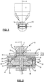
- FIG. 1 and 2 illustrated first embodiment of a friction stir welding with a friction stir welding according to the invention has a on a handling device (not shown) provided drive 1, with a pin 3 of the friction stir welding tool can be driven in rotation, wherein a drive end 5 of the pin 3 is coupled to the drive 1.
- an engagement portion 9 is formed on the pin 3, which has a cylindrical shape and is provided with an engagement surface 13 extending parallel to the rotation axis 11 of the pin 3.
- a first shoulder element 15 is provided which surrounds the pin 3 and has a first contact surface 17 which extends transversely and in particular perpendicular to the axis of rotation 11 and which is intended to abut against the surface of a workpiece 19.
- the first shoulder element 15 is driven in this preferred embodiment separately from the pin 3 rotationally about the axis of rotation 11. But it is also conceivable that the first shoulder member 15 rotatably connected to the pin 3 or even integrally formed therewith, so that it rotates together with the pin 3.
- a second shoulder member 21 is attached to the pin 3, wherein the second shoulder member 21 has a second abutment surface 23 facing the first abutment surface 17, also transverse and in particular runs perpendicular to the axis of rotation 11.
- the second contact surface 23 is formed on a contact element 25 which is detachably attached to a first shoulder part 27.
- a friction block 31 is rotatably mounted on the pin 3 via an engagement member 29, which has an inclined to the axis of rotation 11 about this circumferential and outwardly facing first friction surface 33.
- the first friction surface 33 is opposite to a second friction surface 35, which also extends inclined to the rotation axis 11 and revolves around it, wherein the second friction surface 35 is formed on a first ring member 37, the rotationally fixed, but axially displaceable in the direction of the axis of rotation 11 on the first shoulder part 27 is held.
- the first ring element 37 is biased by a plate spring 39, which is supported on the first shoulder portion 27, in the axial direction towards the friction block 31, so that the friction surfaces 33, 35 are biased towards each other.
- a third inclined to the axis of rotation 11 and extending around this friction surface 41 is provided on the friction block 31.
- a second shoulder part 43 is provided on the second shoulder element 21, which is axially displaceable, but is rotatably coupled to a second ring member 45 on which an inwardly pointing and inclined to the axis of rotation 11 extending fourth friction surface 47 is formed.
- the second ring element 45 is biased in the axial direction towards the friction block 31 via a second plate spring 49, so that the third and fourth friction surfaces 41, 47 are also biased against one another.
- first shoulder part 27 and the second shoulder part 43 are non-rotatably connected to each other via bolts 51 to which nuts are screwed, and the axial distance between them is fixed by the bolts 51 with the nuts screwed thereon.
- the bias of the plate springs 39, 49 can be adjusted by the nuts, the bias of the plate springs 39, 49, with this bias the friction surfaces 33, 35, 41, 47 against each other.
- a friction stir weld seam can be produced in the workpiece 19 in the manner described below.
- the engaging portion 9 of the friction stir welding tool abuts with an edge of the workpiece 19, and the first abutment surface 17 of the first shoulder member 15 rests on the upper surface of the workpiece 19, while the second abutment surface 23 on the second shoulder member 21 on the lower surface of the workpiece 19th is applied.
- the lower second shoulder element 21 of the friction stir welding tool which is remote from the rotary drive 1, is frictionally coupled to the pin 3.
- first upper shoulder element 15 is also the case with the first upper shoulder element 15 and this is not driven independently of the pin 3, but is also frictionally connected to the pin 3.
- only the first upper shoulder element is frictionally coupled in the manner described with the pin 3, so as to limit the friction energy introduced via this shoulder element.
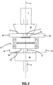
- Fig. 3 and 4 illustrated second embodiment of a friction stir welding according to the invention is provided to weld box sections with a first workpiece portion 19 'and a second, parallel thereto extending workpiece portion 19 ".
- the pin 3 here having a first engagement section 9 'and a second engagement section 9 ", on which engagement surfaces extending parallel to the axis of rotation 11 are formed
- the first shoulder element 15 and a third shoulder element 53 are provided, wherein on the first shoulder element 15 a transverse to the axis of rotation 11 and extending to the second engagement portion 9 'facing first contact surface 17 is formed analogously to the third shoulder member 53 to the second engagement portion 9 ". pointing and also transverse to the axis of rotation 11 extending third contact surface 55 is formed.
- the contact surfaces 17, 55 and the engagement portions 9 ', 9 are, as already described in connection with the first embodiment, provided to come with the workpiece sections 19', 19" to the system, so that in a rotating drive of the pin. 3 by the drive 1 a frictional contact of both the contact surfaces 17, 55 and the engaging portions 9 ', 9 "with the workpiece sections 19', 19" comes about.
- a second shoulder element 21 is arranged between the first engagement section 9 'and the second engagement section 9 ", which is also frictionally coupled to the pin 3.
- the second shoulder element 21' as in FIG Fig. 4 shown, in such a way that it again has a non-rotatably supported on an engaging member 29 on the pin 3 trimmed friction block 31 which extends annularly around the pin 3 around.
- On the friction block 31 is a first, inclined to the axis of rotation 11 extending, annularly around the axis of rotation 11 around extending friction surface 33 is formed.
- first shoulder portion 27 which is annularly disposed around the pin 3 and which has the second bearing surface 23 formed on a releasably attached thereto first abutment element 25, which also here transversely and in particular perpendicular to the axis of rotation 11th extends.
- first ring member 37 is provided which has a second friction surface 35 which is inclined to the axis of rotation 11 and the first friction surface 33 opposite.
- a first plate spring 39 is provided which biases the first ring member 37 in the axial direction with respect to the rotation axis 11 such that the first and second friction surfaces 33, 35 with a through the deformation the first disc spring 39 predetermined bias voltage are pressed against each other.
- the second shoulder element 21 has a second shoulder part 43, which is likewise arranged annularly around the pin 3 and on which a fourth abutment surface 59 is formed by way of a second abutment element 57 releasably secured thereto.
- a second ring member 45 is provided on the second shoulder portion 43, wherein the second ring member 45 a fourth, inclined to the axis of rotation 11 extending and extending annularly around it friction surface 47 has.
- the fourth friction surface 47 of the second, formed on the friction block 31 friction surface 35 is opposite, and the second ring member 45 is biased by a second plate spring 49 in the axial direction toward the friction block 31.
Landscapes
- Engineering & Computer Science (AREA)
- Mechanical Engineering (AREA)
- Pressure Welding/Diffusion-Bonding (AREA)
Priority Applications (6)
| Application Number | Priority Date | Filing Date | Title |
|---|---|---|---|
| PT141843318T PT2995412T (pt) | 2014-09-10 | 2014-09-10 | Ferramenta de soldadura por fricção linear |
| ES14184331.8T ES2652315T3 (es) | 2014-09-10 | 2014-09-10 | Herramienta de soldadura por fricción-agitación |
| EP14184331.8A EP2995412B1 (fr) | 2014-09-10 | 2014-09-10 | Outil de soudage par friction malaxage |
| BR102015021246A BR102015021246A2 (pt) | 2014-09-10 | 2015-09-01 | ferramenta de solda por fricção e mistura mecânica |
| US14/845,536 US9457513B2 (en) | 2014-09-10 | 2015-09-04 | Friction stir welding tool |
| CA2902949A CA2902949A1 (fr) | 2014-09-10 | 2015-09-04 | Outil de soudage par friction-malaxage |
Applications Claiming Priority (1)
| Application Number | Priority Date | Filing Date | Title |
|---|---|---|---|
| EP14184331.8A EP2995412B1 (fr) | 2014-09-10 | 2014-09-10 | Outil de soudage par friction malaxage |
Publications (2)
| Publication Number | Publication Date |
|---|---|
| EP2995412A1 true EP2995412A1 (fr) | 2016-03-16 |
| EP2995412B1 EP2995412B1 (fr) | 2017-11-08 |
Family
ID=51518643
Family Applications (1)
| Application Number | Title | Priority Date | Filing Date |
|---|---|---|---|
| EP14184331.8A Not-in-force EP2995412B1 (fr) | 2014-09-10 | 2014-09-10 | Outil de soudage par friction malaxage |
Country Status (6)
| Country | Link |
|---|---|
| US (1) | US9457513B2 (fr) |
| EP (1) | EP2995412B1 (fr) |
| BR (1) | BR102015021246A2 (fr) |
| CA (1) | CA2902949A1 (fr) |
| ES (1) | ES2652315T3 (fr) |
| PT (1) | PT2995412T (fr) |
Families Citing this family (11)
| Publication number | Priority date | Publication date | Assignee | Title |
|---|---|---|---|---|
| JP6084887B2 (ja) * | 2013-04-16 | 2017-02-22 | 川崎重工業株式会社 | 摩擦撹拌接合装置および摩擦撹拌接合方法 |
| PT3069812T (pt) | 2015-03-18 | 2017-12-21 | Helmholtz-Zentrum Geesthacht Zentrum für Material-und Küstenforschung GmbH | Aparelho para soldadura por fricção linear com um contacto que compreende primeiro e segundo orifícios de passagem |
| PT3078480T (pt) | 2015-04-10 | 2019-09-26 | Helmholtz Zentrum Geesthacht | Método para ligar uma peça com superfície estruturada a uma peça de plástico |
| US10799980B2 (en) * | 2016-10-06 | 2020-10-13 | Mazak Corporation | Compressible friction stir welding tool for conventional machining equipment |
| CN106541579B (zh) * | 2016-11-04 | 2018-12-04 | 东阳市善水环境工程有限公司 | 一种橡筋加工的缝纫装置 |
| JP7150570B2 (ja) * | 2018-11-13 | 2022-10-11 | 川崎重工業株式会社 | 摩擦撹拌接合用ツール及び摩擦撹拌接合方法 |
| EP3822019B1 (fr) | 2019-11-15 | 2024-01-10 | Helmholtz-Zentrum hereon GmbH | Dispositif et procédé d'application d'une couche de matériau à une zone de surface d'une pièce |
| US11331747B1 (en) | 2019-11-20 | 2022-05-17 | United States Of America As Represented By The Administrator Of Nasa | Self-reacting friction stir welding tool |
| US20250091155A1 (en) * | 2022-12-08 | 2025-03-20 | The Boeing Company | Friction stir welding tool and welding method |
| US12220761B2 (en) * | 2022-12-08 | 2025-02-11 | The Boeing Company | Friction stir welding tool and welding method |
| CN116046237B (zh) * | 2023-01-19 | 2025-05-06 | 沈阳工业大学 | 一种用于搅拌摩擦焊的轴向力检测装置 |
Citations (2)
| Publication number | Priority date | Publication date | Assignee | Title |
|---|---|---|---|---|
| WO2006081819A1 (fr) * | 2005-02-01 | 2006-08-10 | Dan Stir Aps | Dispositif pour soudage par melange par friction et procede de soudage |
| EP2639006A1 (fr) * | 2011-10-14 | 2013-09-18 | Nippon Sharyo Ltd. | Dispositif de soudage par friction malaxage |
Family Cites Families (4)
| Publication number | Priority date | Publication date | Assignee | Title |
|---|---|---|---|---|
| US6237835B1 (en) * | 2000-02-29 | 2001-05-29 | The Boeing Company | Method and apparatus for backing up a friction stir weld joint |
| US20090120995A1 (en) * | 2007-11-08 | 2009-05-14 | Battelle Energy Alliance, Llc | Friction stir weld tools, methods of manufacturing such tools, and methods of thin sheet bonding using such tools |
| US8052028B2 (en) * | 2008-06-16 | 2011-11-08 | GM Global Technology Operations LLC | Device for use with a friction stir spot welding (FSSW) apparatus |
| DE102011015831B3 (de) * | 2011-04-01 | 2012-07-26 | Helmholtz-Zentrum Geesthacht Zentrum für Material- und Küstenforschung GmbH | Vorrichtung zum Reibrührschweißen |
-
2014
- 2014-09-10 PT PT141843318T patent/PT2995412T/pt unknown
- 2014-09-10 ES ES14184331.8T patent/ES2652315T3/es active Active
- 2014-09-10 EP EP14184331.8A patent/EP2995412B1/fr not_active Not-in-force
-
2015
- 2015-09-01 BR BR102015021246A patent/BR102015021246A2/pt not_active IP Right Cessation
- 2015-09-04 US US14/845,536 patent/US9457513B2/en not_active Expired - Fee Related
- 2015-09-04 CA CA2902949A patent/CA2902949A1/fr not_active Abandoned
Patent Citations (2)
| Publication number | Priority date | Publication date | Assignee | Title |
|---|---|---|---|---|
| WO2006081819A1 (fr) * | 2005-02-01 | 2006-08-10 | Dan Stir Aps | Dispositif pour soudage par melange par friction et procede de soudage |
| EP2639006A1 (fr) * | 2011-10-14 | 2013-09-18 | Nippon Sharyo Ltd. | Dispositif de soudage par friction malaxage |
Also Published As
| Publication number | Publication date |
|---|---|
| ES2652315T3 (es) | 2018-02-01 |
| US9457513B2 (en) | 2016-10-04 |
| BR102015021246A2 (pt) | 2016-05-31 |
| CA2902949A1 (fr) | 2016-03-10 |
| PT2995412T (pt) | 2017-12-22 |
| US20160067818A1 (en) | 2016-03-10 |
| EP2995412B1 (fr) | 2017-11-08 |
Similar Documents
| Publication | Publication Date | Title |
|---|---|---|
| EP2995412B1 (fr) | Outil de soudage par friction malaxage | |
| EP2505296B1 (fr) | Dispositif de soudage par friction-malaxage | |
| DE102009024758B4 (de) | Vorrichtung zur Verwendung mit einem Schweißgerät, insbesondere einem Reibrührpunktschweißgerät (FSSW-Gerät) | |
| EP2213419A1 (fr) | Outil manuel à moteur doté d'un dispositif de serrage pour un outil | |
| DE29919877U1 (de) | Elektromotorische Verstelleinrichtung | |
| DE2527280A1 (de) | Antriebsvorrichtung, vorzugsweise zum gewindeschneiden | |
| DE202017003037U1 (de) | Präzisionsspannfutter mit bogenförmigen Schienen | |
| EP0286837B1 (fr) | Unité de coupe | |
| EP2576133A1 (fr) | Tourelle revolver | |
| DE102014218039B3 (de) | Spannvorrichtung | |
| DE2629686A1 (de) | Zahnstangentrieb fuer ein lenkgetriebe | |
| DE102012206285A1 (de) | Bearbeitungsmaschine in Ständerbauart | |
| EP2995411A1 (fr) | Appareil pour soudage par friction malaxage | |
| DE3913898A1 (de) | Einrichtung zur axialen sicherung, zum verriegeln und zum drehverstellen der schutzhaube auf dem spannhals von handwerkzeugmaschinen | |
| CH629991A5 (de) | Klemmvorrichtung fuer die spindelhuelse einer fraes- und bohrspindel. | |
| EP2428316B1 (fr) | Machine-outil, notamment meuleuse d'angle manuelle | |
| EP3006143A1 (fr) | Mandrin | |
| EP2260974A1 (fr) | Support de pièce usée pour une rectifieuse plane | |
| EP1559509B1 (fr) | Dispositif de fixation d'un outil de meulage à une machine-outil | |
| DE523316C (de) | Als Ganzes einsetzbarer Werkzeughalter mit einer beim UEberschreiten eines bestimmten Drehmomentes selbsttaetig ausrueckenden Klauenkupplung | |
| DE2410114A1 (de) | Vorrichtung zur drehmomentabschaltung als ueberlastungssicherung eines getriebes | |
| EP1775058A1 (fr) | Outil de soudage par friction agitation avec support de pièce rotatif pour assemblage à un manipulateur | |
| DE19837147C5 (de) | Spannfutter für Werkzeugmaschinen | |
| EP3597299A1 (fr) | Groupe de rouleaux, dispositif de broyage et procédé de réglage de la fente de broyage d'un dispositif de broyage | |
| DE2554114C2 (de) | Vorrichtung zur Steuerung der Zustellbewegung eines Schleifwerkzeuges, insbesondere eines Honwerkzeuges |
Legal Events
| Date | Code | Title | Description |
|---|---|---|---|
| PUAI | Public reference made under article 153(3) epc to a published international application that has entered the european phase |
Free format text: ORIGINAL CODE: 0009012 |
|
| AK | Designated contracting states |
Kind code of ref document: A1 Designated state(s): AL AT BE BG CH CY CZ DE DK EE ES FI FR GB GR HR HU IE IS IT LI LT LU LV MC MK MT NL NO PL PT RO RS SE SI SK SM TR |
|
| AX | Request for extension of the european patent |
Extension state: BA ME |
|
| 17P | Request for examination filed |
Effective date: 20160309 |
|
| RBV | Designated contracting states (corrected) |
Designated state(s): AL AT BE BG CH CY CZ DE DK EE ES FI FR GB GR HR HU IE IS IT LI LT LU LV MC MK MT NL NO PL PT RO RS SE SI SK SM TR |
|
| RIC1 | Information provided on ipc code assigned before grant |
Ipc: B23K 20/12 20060101AFI20170113BHEP |
|
| GRAP | Despatch of communication of intention to grant a patent |
Free format text: ORIGINAL CODE: EPIDOSNIGR1 |
|
| INTG | Intention to grant announced |
Effective date: 20170322 |
|
| GRAS | Grant fee paid |
Free format text: ORIGINAL CODE: EPIDOSNIGR3 |
|
| GRAA | (expected) grant |
Free format text: ORIGINAL CODE: 0009210 |
|
| AK | Designated contracting states |
Kind code of ref document: B1 Designated state(s): AL AT BE BG CH CY CZ DE DK EE ES FI FR GB GR HR HU IE IS IT LI LT LU LV MC MK MT NL NO PL PT RO RS SE SI SK SM TR |
|
| REG | Reference to a national code |
Ref country code: GB Ref legal event code: FG4D Free format text: NOT ENGLISH |
|
| REG | Reference to a national code |
Ref country code: CH Ref legal event code: EP Ref country code: AT Ref legal event code: REF Ref document number: 943682 Country of ref document: AT Kind code of ref document: T Effective date: 20171115 |
|
| REG | Reference to a national code |
Ref country code: IE Ref legal event code: FG4D Free format text: LANGUAGE OF EP DOCUMENT: GERMAN |
|
| REG | Reference to a national code |
Ref country code: DE Ref legal event code: R096 Ref document number: 502014006123 Country of ref document: DE |
|
| REG | Reference to a national code |
Ref country code: PT Ref legal event code: SC4A Ref document number: 2995412 Country of ref document: PT Date of ref document: 20171222 Kind code of ref document: T Free format text: AVAILABILITY OF NATIONAL TRANSLATION Effective date: 20171214 |
|
| REG | Reference to a national code |
Ref country code: SE Ref legal event code: TRGR |
|
| REG | Reference to a national code |
Ref country code: ES Ref legal event code: FG2A Ref document number: 2652315 Country of ref document: ES Kind code of ref document: T3 Effective date: 20180201 |
|
| REG | Reference to a national code |
Ref country code: NL Ref legal event code: MP Effective date: 20171108 |
|
| REG | Reference to a national code |
Ref country code: LT Ref legal event code: MG4D |
|
| PG25 | Lapsed in a contracting state [announced via postgrant information from national office to epo] |
Ref country code: NO Free format text: LAPSE BECAUSE OF FAILURE TO SUBMIT A TRANSLATION OF THE DESCRIPTION OR TO PAY THE FEE WITHIN THE PRESCRIBED TIME-LIMIT Effective date: 20180208 Ref country code: NL Free format text: LAPSE BECAUSE OF FAILURE TO SUBMIT A TRANSLATION OF THE DESCRIPTION OR TO PAY THE FEE WITHIN THE PRESCRIBED TIME-LIMIT Effective date: 20171108 Ref country code: LT Free format text: LAPSE BECAUSE OF FAILURE TO SUBMIT A TRANSLATION OF THE DESCRIPTION OR TO PAY THE FEE WITHIN THE PRESCRIBED TIME-LIMIT Effective date: 20171108 Ref country code: FI Free format text: LAPSE BECAUSE OF FAILURE TO SUBMIT A TRANSLATION OF THE DESCRIPTION OR TO PAY THE FEE WITHIN THE PRESCRIBED TIME-LIMIT Effective date: 20171108 |
|
| PG25 | Lapsed in a contracting state [announced via postgrant information from national office to epo] |
Ref country code: HR Free format text: LAPSE BECAUSE OF FAILURE TO SUBMIT A TRANSLATION OF THE DESCRIPTION OR TO PAY THE FEE WITHIN THE PRESCRIBED TIME-LIMIT Effective date: 20171108 Ref country code: GR Free format text: LAPSE BECAUSE OF FAILURE TO SUBMIT A TRANSLATION OF THE DESCRIPTION OR TO PAY THE FEE WITHIN THE PRESCRIBED TIME-LIMIT Effective date: 20180209 Ref country code: IS Free format text: LAPSE BECAUSE OF FAILURE TO SUBMIT A TRANSLATION OF THE DESCRIPTION OR TO PAY THE FEE WITHIN THE PRESCRIBED TIME-LIMIT Effective date: 20180308 Ref country code: BG Free format text: LAPSE BECAUSE OF FAILURE TO SUBMIT A TRANSLATION OF THE DESCRIPTION OR TO PAY THE FEE WITHIN THE PRESCRIBED TIME-LIMIT Effective date: 20180208 Ref country code: RS Free format text: LAPSE BECAUSE OF FAILURE TO SUBMIT A TRANSLATION OF THE DESCRIPTION OR TO PAY THE FEE WITHIN THE PRESCRIBED TIME-LIMIT Effective date: 20171108 Ref country code: LV Free format text: LAPSE BECAUSE OF FAILURE TO SUBMIT A TRANSLATION OF THE DESCRIPTION OR TO PAY THE FEE WITHIN THE PRESCRIBED TIME-LIMIT Effective date: 20171108 |
|
| PG25 | Lapsed in a contracting state [announced via postgrant information from national office to epo] |
Ref country code: CZ Free format text: LAPSE BECAUSE OF FAILURE TO SUBMIT A TRANSLATION OF THE DESCRIPTION OR TO PAY THE FEE WITHIN THE PRESCRIBED TIME-LIMIT Effective date: 20171108 Ref country code: EE Free format text: LAPSE BECAUSE OF FAILURE TO SUBMIT A TRANSLATION OF THE DESCRIPTION OR TO PAY THE FEE WITHIN THE PRESCRIBED TIME-LIMIT Effective date: 20171108 Ref country code: CY Free format text: LAPSE BECAUSE OF FAILURE TO SUBMIT A TRANSLATION OF THE DESCRIPTION OR TO PAY THE FEE WITHIN THE PRESCRIBED TIME-LIMIT Effective date: 20171108 Ref country code: DK Free format text: LAPSE BECAUSE OF FAILURE TO SUBMIT A TRANSLATION OF THE DESCRIPTION OR TO PAY THE FEE WITHIN THE PRESCRIBED TIME-LIMIT Effective date: 20171108 Ref country code: SK Free format text: LAPSE BECAUSE OF FAILURE TO SUBMIT A TRANSLATION OF THE DESCRIPTION OR TO PAY THE FEE WITHIN THE PRESCRIBED TIME-LIMIT Effective date: 20171108 |
|
| REG | Reference to a national code |
Ref country code: DE Ref legal event code: R097 Ref document number: 502014006123 Country of ref document: DE |
|
| PG25 | Lapsed in a contracting state [announced via postgrant information from national office to epo] |
Ref country code: RO Free format text: LAPSE BECAUSE OF FAILURE TO SUBMIT A TRANSLATION OF THE DESCRIPTION OR TO PAY THE FEE WITHIN THE PRESCRIBED TIME-LIMIT Effective date: 20171108 Ref country code: SM Free format text: LAPSE BECAUSE OF FAILURE TO SUBMIT A TRANSLATION OF THE DESCRIPTION OR TO PAY THE FEE WITHIN THE PRESCRIBED TIME-LIMIT Effective date: 20171108 Ref country code: PL Free format text: LAPSE BECAUSE OF FAILURE TO SUBMIT A TRANSLATION OF THE DESCRIPTION OR TO PAY THE FEE WITHIN THE PRESCRIBED TIME-LIMIT Effective date: 20171108 |
|
| PLBE | No opposition filed within time limit |
Free format text: ORIGINAL CODE: 0009261 |
|
| STAA | Information on the status of an ep patent application or granted ep patent |
Free format text: STATUS: NO OPPOSITION FILED WITHIN TIME LIMIT |
|
| REG | Reference to a national code |
Ref country code: FR Ref legal event code: PLFP Year of fee payment: 5 |
|
| PG25 | Lapsed in a contracting state [announced via postgrant information from national office to epo] |
Ref country code: MT Free format text: LAPSE BECAUSE OF FAILURE TO SUBMIT A TRANSLATION OF THE DESCRIPTION OR TO PAY THE FEE WITHIN THE PRESCRIBED TIME-LIMIT Effective date: 20171108 |
|
| 26N | No opposition filed |
Effective date: 20180809 |
|
| PG25 | Lapsed in a contracting state [announced via postgrant information from national office to epo] |
Ref country code: SI Free format text: LAPSE BECAUSE OF FAILURE TO SUBMIT A TRANSLATION OF THE DESCRIPTION OR TO PAY THE FEE WITHIN THE PRESCRIBED TIME-LIMIT Effective date: 20171108 |
|
| PG25 | Lapsed in a contracting state [announced via postgrant information from national office to epo] |
Ref country code: MC Free format text: LAPSE BECAUSE OF FAILURE TO SUBMIT A TRANSLATION OF THE DESCRIPTION OR TO PAY THE FEE WITHIN THE PRESCRIBED TIME-LIMIT Effective date: 20171108 |
|
| REG | Reference to a national code |
Ref country code: CH Ref legal event code: PL |
|
| REG | Reference to a national code |
Ref country code: BE Ref legal event code: MM Effective date: 20180930 |
|
| REG | Reference to a national code |
Ref country code: IE Ref legal event code: MM4A |
|
| PG25 | Lapsed in a contracting state [announced via postgrant information from national office to epo] |
Ref country code: LU Free format text: LAPSE BECAUSE OF NON-PAYMENT OF DUE FEES Effective date: 20180910 |
|
| PG25 | Lapsed in a contracting state [announced via postgrant information from national office to epo] |
Ref country code: IE Free format text: LAPSE BECAUSE OF NON-PAYMENT OF DUE FEES Effective date: 20180910 |
|
| PG25 | Lapsed in a contracting state [announced via postgrant information from national office to epo] |
Ref country code: CH Free format text: LAPSE BECAUSE OF NON-PAYMENT OF DUE FEES Effective date: 20180930 Ref country code: LI Free format text: LAPSE BECAUSE OF NON-PAYMENT OF DUE FEES Effective date: 20180930 Ref country code: BE Free format text: LAPSE BECAUSE OF NON-PAYMENT OF DUE FEES Effective date: 20180930 |
|
| PG25 | Lapsed in a contracting state [announced via postgrant information from national office to epo] |
Ref country code: TR Free format text: LAPSE BECAUSE OF FAILURE TO SUBMIT A TRANSLATION OF THE DESCRIPTION OR TO PAY THE FEE WITHIN THE PRESCRIBED TIME-LIMIT Effective date: 20171108 |
|
| PG25 | Lapsed in a contracting state [announced via postgrant information from national office to epo] |
Ref country code: HU Free format text: LAPSE BECAUSE OF FAILURE TO SUBMIT A TRANSLATION OF THE DESCRIPTION OR TO PAY THE FEE WITHIN THE PRESCRIBED TIME-LIMIT; INVALID AB INITIO Effective date: 20140910 Ref country code: MK Free format text: LAPSE BECAUSE OF NON-PAYMENT OF DUE FEES Effective date: 20171108 |
|
| PG25 | Lapsed in a contracting state [announced via postgrant information from national office to epo] |
Ref country code: AL Free format text: LAPSE BECAUSE OF FAILURE TO SUBMIT A TRANSLATION OF THE DESCRIPTION OR TO PAY THE FEE WITHIN THE PRESCRIBED TIME-LIMIT Effective date: 20171108 |
|
| REG | Reference to a national code |
Ref country code: AT Ref legal event code: MM01 Ref document number: 943682 Country of ref document: AT Kind code of ref document: T Effective date: 20190910 |
|
| PG25 | Lapsed in a contracting state [announced via postgrant information from national office to epo] |
Ref country code: AT Free format text: LAPSE BECAUSE OF NON-PAYMENT OF DUE FEES Effective date: 20190910 |
|
| PGFP | Annual fee paid to national office [announced via postgrant information from national office to epo] |
Ref country code: SE Payment date: 20220922 Year of fee payment: 9 Ref country code: PT Payment date: 20220901 Year of fee payment: 9 Ref country code: GB Payment date: 20220927 Year of fee payment: 9 Ref country code: DE Payment date: 20220920 Year of fee payment: 9 |
|
| PGFP | Annual fee paid to national office [announced via postgrant information from national office to epo] |
Ref country code: FR Payment date: 20220921 Year of fee payment: 9 |
|
| PGFP | Annual fee paid to national office [announced via postgrant information from national office to epo] |
Ref country code: IT Payment date: 20220930 Year of fee payment: 9 Ref country code: ES Payment date: 20221018 Year of fee payment: 9 |
|
| REG | Reference to a national code |
Ref country code: DE Ref legal event code: R119 Ref document number: 502014006123 Country of ref document: DE |
|
| PG25 | Lapsed in a contracting state [announced via postgrant information from national office to epo] |
Ref country code: PT Free format text: LAPSE BECAUSE OF NON-PAYMENT OF DUE FEES Effective date: 20240311 |
|
| REG | Reference to a national code |
Ref country code: SE Ref legal event code: EUG |
|
| GBPC | Gb: european patent ceased through non-payment of renewal fee |
Effective date: 20230910 |
|
| PG25 | Lapsed in a contracting state [announced via postgrant information from national office to epo] |
Ref country code: GB Free format text: LAPSE BECAUSE OF NON-PAYMENT OF DUE FEES Effective date: 20230910 |
|
| PG25 | Lapsed in a contracting state [announced via postgrant information from national office to epo] |
Ref country code: GB Free format text: LAPSE BECAUSE OF NON-PAYMENT OF DUE FEES Effective date: 20230910 Ref country code: FR Free format text: LAPSE BECAUSE OF NON-PAYMENT OF DUE FEES Effective date: 20230930 Ref country code: DE Free format text: LAPSE BECAUSE OF NON-PAYMENT OF DUE FEES Effective date: 20240403 |
|
| PG25 | Lapsed in a contracting state [announced via postgrant information from national office to epo] |
Ref country code: SE Free format text: LAPSE BECAUSE OF NON-PAYMENT OF DUE FEES Effective date: 20230911 |
|
| REG | Reference to a national code |
Ref country code: ES Ref legal event code: FD2A Effective date: 20241028 |
|
| PG25 | Lapsed in a contracting state [announced via postgrant information from national office to epo] |
Ref country code: IT Free format text: LAPSE BECAUSE OF NON-PAYMENT OF DUE FEES Effective date: 20230910 |
|
| PG25 | Lapsed in a contracting state [announced via postgrant information from national office to epo] |
Ref country code: IT Free format text: LAPSE BECAUSE OF NON-PAYMENT OF DUE FEES Effective date: 20230910 |
|
| PG25 | Lapsed in a contracting state [announced via postgrant information from national office to epo] |
Ref country code: ES Free format text: LAPSE BECAUSE OF NON-PAYMENT OF DUE FEES Effective date: 20230911 |
|
| PG25 | Lapsed in a contracting state [announced via postgrant information from national office to epo] |
Ref country code: ES Free format text: LAPSE BECAUSE OF NON-PAYMENT OF DUE FEES Effective date: 20230911 |