EP2995419B1 - Machine tool - Google Patents
Machine tool Download PDFInfo
- Publication number
- EP2995419B1 EP2995419B1 EP15183545.1A EP15183545A EP2995419B1 EP 2995419 B1 EP2995419 B1 EP 2995419B1 EP 15183545 A EP15183545 A EP 15183545A EP 2995419 B1 EP2995419 B1 EP 2995419B1
- Authority
- EP
- European Patent Office
- Prior art keywords
- spindle
- workpiece
- tool carrier
- carrier unit
- tool
- Prior art date
- Legal status (The legal status is an assumption and is not a legal conclusion. Google has not performed a legal analysis and makes no representation as to the accuracy of the status listed.)
- Active
Links
Images

Classifications
-
- B—PERFORMING OPERATIONS; TRANSPORTING
- B23—MACHINE TOOLS; METAL-WORKING NOT OTHERWISE PROVIDED FOR
- B23Q—DETAILS, COMPONENTS, OR ACCESSORIES FOR MACHINE TOOLS, e.g. ARRANGEMENTS FOR COPYING OR CONTROLLING; MACHINE TOOLS IN GENERAL CHARACTERISED BY THE CONSTRUCTION OF PARTICULAR DETAILS OR COMPONENTS; COMBINATIONS OR ASSOCIATIONS OF METAL-WORKING MACHINES, NOT DIRECTED TO A PARTICULAR RESULT
- B23Q39/00—Metal-working machines incorporating a plurality of sub-assemblies, each capable of performing a metal-working operation
- B23Q39/02—Metal-working machines incorporating a plurality of sub-assemblies, each capable of performing a metal-working operation the sub-assemblies being capable of being brought to act at a single operating station
- B23Q39/021—Metal-working machines incorporating a plurality of sub-assemblies, each capable of performing a metal-working operation the sub-assemblies being capable of being brought to act at a single operating station with a plurality of toolheads per workholder, whereby the toolhead is a main spindle, a multispindle, a revolver or the like
-
- B—PERFORMING OPERATIONS; TRANSPORTING
- B23—MACHINE TOOLS; METAL-WORKING NOT OTHERWISE PROVIDED FOR
- B23Q—DETAILS, COMPONENTS, OR ACCESSORIES FOR MACHINE TOOLS, e.g. ARRANGEMENTS FOR COPYING OR CONTROLLING; MACHINE TOOLS IN GENERAL CHARACTERISED BY THE CONSTRUCTION OF PARTICULAR DETAILS OR COMPONENTS; COMBINATIONS OR ASSOCIATIONS OF METAL-WORKING MACHINES, NOT DIRECTED TO A PARTICULAR RESULT
- B23Q1/00—Members which are comprised in the general build-up of a form of machine, particularly relatively large fixed members
- B23Q1/25—Movable or adjustable work or tool supports
-
- B—PERFORMING OPERATIONS; TRANSPORTING
- B23—MACHINE TOOLS; METAL-WORKING NOT OTHERWISE PROVIDED FOR
- B23B—TURNING; BORING
- B23B3/00—General-purpose turning-machines or devices, e.g. centre lathes with feed rod and lead screw; Sets of turning-machines
- B23B3/30—Turning-machines with two or more working-spindles, e.g. in fixed arrangement
-
- B—PERFORMING OPERATIONS; TRANSPORTING
- B23—MACHINE TOOLS; METAL-WORKING NOT OTHERWISE PROVIDED FOR
- B23Q—DETAILS, COMPONENTS, OR ACCESSORIES FOR MACHINE TOOLS, e.g. ARRANGEMENTS FOR COPYING OR CONTROLLING; MACHINE TOOLS IN GENERAL CHARACTERISED BY THE CONSTRUCTION OF PARTICULAR DETAILS OR COMPONENTS; COMBINATIONS OR ASSOCIATIONS OF METAL-WORKING MACHINES, NOT DIRECTED TO A PARTICULAR RESULT
- B23Q1/00—Members which are comprised in the general build-up of a form of machine, particularly relatively large fixed members
- B23Q1/01—Frames, beds, pillars or like members; Arrangement of ways
- B23Q1/017—Arrangements of ways
-
- B—PERFORMING OPERATIONS; TRANSPORTING
- B23—MACHINE TOOLS; METAL-WORKING NOT OTHERWISE PROVIDED FOR
- B23Q—DETAILS, COMPONENTS, OR ACCESSORIES FOR MACHINE TOOLS, e.g. ARRANGEMENTS FOR COPYING OR CONTROLLING; MACHINE TOOLS IN GENERAL CHARACTERISED BY THE CONSTRUCTION OF PARTICULAR DETAILS OR COMPONENTS; COMBINATIONS OR ASSOCIATIONS OF METAL-WORKING MACHINES, NOT DIRECTED TO A PARTICULAR RESULT
- B23Q3/00—Devices holding, supporting, or positioning work or tools, of a kind normally removable from the machine
- B23Q3/155—Arrangements for automatic insertion or removal of tools, e.g. combined with manual handling
- B23Q3/1552—Arrangements for automatic insertion or removal of tools, e.g. combined with manual handling parts of devices for automatically inserting or removing tools
- B23Q3/15553—Tensioning devices or tool holders, e.g. grippers
-
- B—PERFORMING OPERATIONS; TRANSPORTING
- B23—MACHINE TOOLS; METAL-WORKING NOT OTHERWISE PROVIDED FOR
- B23Q—DETAILS, COMPONENTS, OR ACCESSORIES FOR MACHINE TOOLS, e.g. ARRANGEMENTS FOR COPYING OR CONTROLLING; MACHINE TOOLS IN GENERAL CHARACTERISED BY THE CONSTRUCTION OF PARTICULAR DETAILS OR COMPONENTS; COMBINATIONS OR ASSOCIATIONS OF METAL-WORKING MACHINES, NOT DIRECTED TO A PARTICULAR RESULT
- B23Q39/00—Metal-working machines incorporating a plurality of sub-assemblies, each capable of performing a metal-working operation
- B23Q39/02—Metal-working machines incorporating a plurality of sub-assemblies, each capable of performing a metal-working operation the sub-assemblies being capable of being brought to act at a single operating station
- B23Q39/021—Metal-working machines incorporating a plurality of sub-assemblies, each capable of performing a metal-working operation the sub-assemblies being capable of being brought to act at a single operating station with a plurality of toolheads per workholder, whereby the toolhead is a main spindle, a multispindle, a revolver or the like
- B23Q39/022—Metal-working machines incorporating a plurality of sub-assemblies, each capable of performing a metal-working operation the sub-assemblies being capable of being brought to act at a single operating station with a plurality of toolheads per workholder, whereby the toolhead is a main spindle, a multispindle, a revolver or the like with same working direction of toolheads on same workholder
- B23Q39/023—Metal-working machines incorporating a plurality of sub-assemblies, each capable of performing a metal-working operation the sub-assemblies being capable of being brought to act at a single operating station with a plurality of toolheads per workholder, whereby the toolhead is a main spindle, a multispindle, a revolver or the like with same working direction of toolheads on same workholder simultaneous working of toolheads
Definitions
- the invention relates to a machine tool having a machine frame, which comprises a machine bed having a machine bed body extending in a longitudinal direction, the underside of an opposite surface of the machine tool facing bottom, a bottom side opposite and facing away from the bottom top and a between the bottom and the top transverse to the underside extending front side, comprising two arranged on the machine bed workpiece spindle units, which are held by spindle supports and each of which has a workpiece holder which is rotatable about a respective spindle axis, wherein the workpiece spindle units are arranged on the machine bed, that the spindle axes are aligned coaxially with each other, so that a workpiece for processing on the front and the back in a workpiece transfer position can be transferred, wherein the workpiece spindle units holding Spindle support are held on the upper side of the machine bed body and at least one arranged on the machine bed and supported by a lower carriage system lower tool carrier unit, wherein the at least one lower carriage system disposed on
- Such machine tools are for example from the DE 199 11 156 A1 known.
- the invention has the object to improve a machine tool so that with this optimal mobility of the workpiece spindle units and the lower tool carrier units relative to each other is possible.
- the at least two lower slide systems can be moved with the respective tool carrier unit in the Z direction until it is in the parked position reach outside of a processing range, which extends between perpendicular to the respective spindle axes extending and one end face of the respective workpiece holder contacting boundary levels in the Z-direction.
- At least one of the lower carriage systems can be moved out of the machining area by standing in the parking position, so that one additional unit or the other lower carriage system, for example for machining shaft parts, collides in the entire machining area without collision with the carriage system in the parking position can be used.
- the machining with the machine tool according to the invention can be realized particularly advantageously by the fact that the at least two lower slide systems are movably guided on the machine bed body in the Z direction, that in every possible, that is both at the minimum and at the maximum extent of the machining area in the Z direction, the tools of the respective lower tool carrier unit can be used within the entire processing area.
- the respective lower carriage system of the lower tool carrier unit in Z-direction has such a large mobility that even with maximum expansion of the machining area each tool of the tool carrier units within the entire processing area, that is from one boundary plane to the other boundary plane, can be used.
- one of the linear guides running in the Z direction could also be arranged on the lower side of the machine bed body.
- the linear guides extending in the Z direction for the at least one carriage system are arranged on the front side of the machine bed body.
- spindle axes extend in the workpiece transfer position in an X / Z plane, which is parallel to the Z-direction of the machine tool and inclined relative to a vertical by an angle of 30 ° or less.
- the X / Z plane is angled 20 ° or less from the vertical, and it is particularly favorable if the X / Z plane is inclined at an angle of 10 ° or less to the vertical runs.
- the lower carriage system and in particular also the at least one lower tool carrier unit are below a horizontal plane running through the spindle axes in the workpiece transfer position.
- the at least one lower slide system and in particular also the at least one tool carrier unit lies below the workpieces to be machined and thus is moved towards the workpieces from below for machining the workpieces.
- the two spindle axes of the workpiece spindle units are always aligned parallel to each other.
- the carriage system in the park position and the respective tool carrier unit carried by it are at a distance from the closest boundary plane of the processing space in the parking position, which corresponds in particular to at least one distance of a tool mount from a system boundary plane running parallel to the boundary plane Position is defined by a maximum extent of the other of the carriage systems with the respective carried by this tool carrier unit, optionally with the tools, in the direction of the boundary plane.
- a further advantageous determination of the parking position provides that the respective lower tool carrier unit can be positioned in a parking position which lies between two spindle end planes defined by the respective workpiece spindle unit, which are perpendicular to the respective spindle axis and fixed in the Z direction by mutually opposite ends of the workpiece spindle units are.
- a further favorable solution provides that the at least one lower carriage system and the respective lower tool carrier unit carried by the latter can be positioned at least in one half of an extension of the respective tool carrier unit in the Z direction corresponding distance from the respective boundary plane and outside the machining area.
- the tools of the respective lower tool carrier units are arranged above edge regions of the respective lower slide systems facing each other.
- an advantageous solution provides that the respective lower tool carrier unit is movable relative to the machine bed body in the Z direction and in the X direction by the respective lower carriage system.
- the respective lower tool carrier unit is additionally movable in the Y direction by the respective carriage system.
- the respective lower tool carrier unit can be positioned in the X and / or Y direction by the respective lower carriage system in such a way that it can be moved past the workpiece holder of the respective workpiece spindle unit in the Z direction.
- the respective lower tool carrier unit can be positioned in the X direction and / or Y direction by the respective lower carriage system in such a way that it can be moved past the respective workpiece spindle unit in the Z direction.
- the respective tool carrier unit could carry auxiliary equipment or grinding units in addition to conventional tools.
- the respective lower tool carrier unit is designed as a tool turret.
- a large number of tools can be used on at least one of the lower tool carrier units, without requiring a large amount of space in the Z direction.
- the space requirement in the Z direction can be reduced in particular if the respective lower tool carrier unit has a turret which is rotatable about a turret axis which is aligned parallel to the Z direction.
- the turret has radially aligned to the turret axis tool holders to also realize a space-saving design in the Z direction.
- an advantageous solution provides that the machine bed body has on the top in the Z-direction extending linear guides on which at least one of the spindle carrier is guided by a Z-slide movable.
- an upper carriage system is guided on the upper side of the machine bed body arranged linear guides and carries an upper tool carrier unit.
- the linear guides for the upper carriage system are identical to the linear guides for the at least one spindle carrier.
- a further advantageous solution which in particular gives high flexibility for machining with the upper tool carrier unit, provides that the linear guides for the upper carriage system extend in the Z direction along the upper side of the machine bed body to such an extent that an opening provided for processing Tool of the upper tool carrier unit with the upper carriage system is positioned within the entire extending between the boundary planes processing area, so that a tool can be used starting at a boundary plane and ending at the other boundary plane.
- an advantageous solution provides that the upper tool carrier unit is movable by the upper carriage system in the Z-direction and the X-direction.
- a further advantageous embodiment provides that the upper tool carrier unit is movable in the Y direction by the upper carriage system.
- the upper tool carrier unit is rotatable about the B-axis by the upper carriage system.
- a favorable solution provides that the upper tool carrier unit has a tool spindle.
- the upper tool carrier unit has a turret.
- the turret is rotatable about a turret axis, the turret axis in particular transversely, preferably perpendicular to the B-axis.
- the tool spindle and the turret are arranged on opposite sides of the upper tool carrier unit.
- An advantageous solution provides that the machine tool is provided with a control which controls all movements of the tool carrier units and the workpiece spindle units for machining workpieces.
- the controller determines the position of the parking positions in the Z direction from dimensions of the workpiece spindle units and their position in the Z direction.
- control is able to adapt the parking positions to the positions of the workpiece spindle units, even with moving workpiece spindle units, and thus also to track the parking positions in accordance with the movements of the workpiece spindle units.
- An exemplary embodiment of a machine tool 10 according to the invention in this case a lathe, comprises a machine frame designated as a whole by 12, which in turn has a machine bed 14, which is arranged above a base 16, in such a way that between the base 16 and the machine bed 14 a free space 18 is present.
- the machine bed 14 is supported at the ends by support members 22 and 24 relative to the base frame 16.
- the machine bed 14 extends in a longitudinal direction 26 between the support elements 22 and 24, so that the free space 18 preferably extends over the entire length of the machine bed 14 between the support elements 22 and 24.
- the machine bed 14 in turn comprises a machine bed body 32, which faces the underframe 16 and thus also a mounting surface 35 for the underframe 16 with a lower side 34.
- a front side 36 and a rear side 38 of the machine bed body 32 extend to an upper side 42 thereof, wherein the upper side 42 of the underside 34 opposite and facing away from this.
- the front linear guide 44 near the front side 36th is arranged on a longitudinal web 48 of the machine bed body 32, while the rear linear guide 46 is disposed near the rear side 38 on the upper side 42.
- an upper linear guide 52 extending in the Z direction is arranged on the front side 36.
- a first recessed region 54 of the front side 36 adjoins the longitudinal web 48, namely in the direction of the underframe 16 or the set-up surface 35, and a second recessed region 56 is provided following the first recessed region 54 near the transition to the underside 34. in which a lower parallel to the Z-axis linear guide 58 is arranged.
- a first lower carriage system 62 and a second lower carriage system 64 are shown, each having a Z-slide 66, the carriage body 68 is disposed in the first recessed area 54 projecting.
- each Z-slide 66 is an X-carriage 72 is guided with linear guides 74 which extend in the X direction, that is perpendicular to the Z-direction, wherein the linear guides 74 preferably parallel to a guide plane 76 extending parallel to the Z Direction extends and preferably inclined relative to a vertical by less than 30 °, preferably less than 20 ° and even better less than 10 °.
- the guide plane 76 runs parallel to a vertical.
- the carriage systems 62 and 64 also comprise a Y-slide 82 which is guided on linear guides 84 running parallel to a Y-direction relative to the X-slide 72, the linear guides 84 being parallel to a guide plane 86 extending perpendicular to the Z-direction.
- the respective Y-carriage 82 of the corresponding carriage system 62 or 64 carries, as in for example Fig. 1 shown, a first and a second lower tool carrier unit 92 and 94, which is exemplified as a tool turret and each having a turret housing 96 on which a turret 98 is rotatably mounted about a turret axis 102.
- the carriage system 62 and 64 and arranged thereon tool carrier units 92 and 94 are preferably mirror-symmetrical to each other, the turrets 98 of the tool carrier units 92 and 94 are arranged facing each other and preferably over mutually facing edge regions 112 and 114 of the carriage system 62 and 64 respectively stand.
- the carriage systems 62 and 64 can be moved by known linear drive systems in both the Z, and in the X and in the Y direction, wherein, for example, either electric linear motors or mechanical linear drives, such as ball screws can be used.
- the Z-slide 66 of each carriage system 62, 64 by means of drive motors 124 driven feed screws 122 are movable, which cooperate with sitting on the Z-slide 66 on opposite sides of the spindle nuts 126.
- feed screws 122 are rotatably mounted at their mutually facing ends in a common bearing unit 128 on the machine bed body 32 and also rotatably and axially non-displaceably mounted on their driven by the drive motors 124, opposite ends in bearing units 129.
- the supply of the carriage systems 62 and 64 preferably takes place via a clearance 132 passing through the cable channel 132, which cooperates with a drag chain arrangement 134, which runs along the back 38.
- the cable channel 132 is firmly connected to the respective Z-slide 66 of the respective carriage system 62 and 64 and moves together with this in the Z-direction.
- the machine tool For receiving workpieces W1 and W2 to be machined, the machine tool is provided with workpiece spindle units 142 and 144 which are respectively held in spindle supports 146 and 148, both spindle supports 146, 148, as in FIG Fig. 3 shown, are held on the upper side 42 of the machine bed body 32.
- the first workpiece spindle unit 142 is arranged stationary relative to the machine bed body 32, so that in this case the spindle carrier 146 with a mounting section 152 is fixedly fixed on the upper side 42 of the machine bed body 32.
- the spindle carrier 148 is movable in the Z direction, and therefore, a mounting portion 154 of the second spindle carrier 148 is seated on a Z-carriage 156 movable by a feed screw drive 158, on the linear guides 44 and 46 extending in the Z-direction , is fixed relative to the machine bed body 32 ( Fig. 4 ).
- the second workpiece spindle unit 144 is slidably controlled in the Z direction relative to the first workpiece spindle unit 142 and thus also relative to the machine bed body 32 in the Z direction.
- first workpiece spindle unit 142 with the mounting portion 152 on a Z-slide and this also by the linear guides 44 and 46 in the Z-direction movable on the machine bed body 32 to lead.
- Each of the workpiece spindle units 142 and 144 is provided with a workpiece holder 162 and 164, respectively, in which the workpieces W1 and W2 are received for machining.
- each of the workpiece receivers 162, 164 is rotatably supported by the respective workpiece spindle units 142, 144 about a respective spindle axis 166, 168, respectively, and also rotatably driven about the respective spindle axis 166, 168 by a spindle drive, not shown, such as an integrated hollow shaft motor.
- the spindle axes 166 and 168 are aligned coaxially with each other, so that for machining a workpiece W1 on the front side, for example in the first workpiece spindle unit 142, the tool can be transferred as workpiece W2 into the second workpiece spindle unit 144 for machining on the rear side in a workpiece transfer position is.
- the second workpiece spindle unit 144 can be moved toward the first workpiece spindle unit 142 in the Z direction, so that the workpiece W1 can be transferred from the first workpiece holder 162 into the second workpiece holder 164.
- the lower tool carrier units 92 and 94 and the lower carriage systems 62, 64 lie below a horizontal plane 169 extending through the spindle axes 166, 168 in the workpiece transfer position.
- a generally designated 172 carriage system is arranged, which is guided on the linear guides 44 and 46 Z-slide 174 and one on the Z-slide 174 guided by parallel to the X-direction linear guides 176 guided X-carriage 178.
- a quill 202 of the carriage system 172 is movable in a Y-direction and rotatably guided about a B-axis parallel to the Y-direction.
- the quill 202 carries a designated as a whole by 182 tool carrier unit, on the one hand a milling spindle 184 which is rotatable about a milling spindle axis 186, and a milling spindle 184 opposite arranged tool turret 188 comprising a turret housing 192 to which a turret 194 to a turret axis 196 is rotatably mounted.
- the turret axis 196 and the milling spindle axis 186 are coaxial with each other and perpendicular to the Y / B axis, wherein the tool carrier unit 182 is movable through the quill 202 along the Y-axis and rotatable about the B-axis.
- the turret 194 is formed so that this radially to the turret axis 196 extending tool receivers 204, in which processing tools 206 can be used.
- a controller 210 which controls the movements of the lower tool carrier units 92 and 94 in the X, Y and Z directions, the movements of the upper tool carrier unit 182 in the X, Y and Z directions and controls the B-axis, which controls rotations of turrets 98 and 194 about the respective turret axes 102 and 196, controls drives of the workpiece spindle units 142 and 144, and controls the Z-direction movements of the second spindle carrier 148.
- the tools 106 of the two tool carrier units 92 and 94 as well as the machining tool 206 of the tool carrier unit 182 can be used on the first workpiece W1, if this is held in the workpiece holder 162 of the first workpiece spindle unit 142 and if necessary driven to rotate about the first spindle axis 166 (FIG. Fig. 5 ).
- the tools 106 of the tool carrier units 92 and 94 as well as the tool 206 of the tool carrier unit 182 can be used to machine the second workpiece W2, if it is held in the second workpiece holder 164 of the second workpiece spindle unit 144 and if necessary rotationally driven about the second spindle axis 168 in Fig. 6 shown.
- the tool 106 of the tool carrier unit 92 is inserted on the first workpiece W1 and the tool 106 of the second tool carrier unit 94 is inserted on the tool W2, the workpiece W1 in the first workpiece holder 162 of the first workpiece spindle unit 142 and the workpiece W2 in the tool holder unit 164 of the second workpiece spindle unit 144 is held.
- the tool 206 of the tool carrier unit 182 can be used on the first workpiece W1 or can be used on the second workpiece W2, as in Fig. 8 shown.
- the tools 106 of the tool carrier units 92 and 94 and 206 of the tool carrier unit 182 are inserted in a processing region 212 which lies between two boundary planes 214 and 216, the first boundary plane 214 being perpendicular to the first spindle axis 166 and the workpiece holder 162 being on an end side 222 , which is facing the opposite tool holder 164, tangent and wherein the second boundary plane 216 in turn is perpendicular to the spindle axis 168 and the workpiece holder 164 also tangent to one of the workpiece holder 162 facing end face 224.
- a workpiece for example a shaft part WT
- a workpiece holder 162 and by the workpiece holder 164 and thus by the first workpiece spindle 142 and the second workpiece spindle 144 simultaneously is driven to edit, and thus to be able to drive through the entire processing area 212 with this tool 106 is as in Fig. 10 shown, for the second tool carrier unit 94 and the second carriage system 64 a in Fig. 10 illustrated parking position P2 is provided, in which both the second tool carrier unit 94 and the second carriage system 64 are disposed outside of the processing area 212, on a second spindle unit 144 side facing the second boundary plane 216th
- the second carriage system 64 with the second tool carrier unit 94 is preferably in the Z direction in a Z position range which approximately corresponds to the Z position range of the second spindle unit 144, so that the second tool carrier unit 94 at a distance AB2 from the second boundary plane 216 is positioned to ensure complete overrunning of the processing area 212 by the tool 106 of the first tool carrier unit 92, without collision occurring between the first tool carrier unit 92 and the second tool carrier unit 94.
- the distance AB2 of the second tool carrier unit 94 from the second delimiting plane 216 preferably corresponds to at least one distance A1 of the tool holder 104 of the tool 106 of the first tool carrier unit 92 from a tool holder unit 94 closest to the second tool carrier unit 94 and tangent to the first tool carrier unit 92 or the first carriage system 62
- System boundary plane 232 for example, the turret 98 tangentially when it protrudes in the direction of the second tool carrier unit 94 via the first carriage system 62.
- the controller 210 sees in this case a coupling of the Z movement of the Z Slats 156 of the spindle carrier 154 and the Z movement of the Z-slide 66 of the carriage system 64, so that both Z-carriages 156 and 66 move synchronously with each other.
- the first tool carrier unit 92 with the first carriage unit 62 is also moved into a parking position P1 in which it is on a side of the first delimiting plane 214 facing away from the processing area 212 and thus on a side of the first delimiting plane 214 facing the first spindle unit 142.
- the distance AB1 of the first tool carrier unit 92 from the first limiting plane 214 preferably corresponds to at least one distance A2 of the tool holder 104 of the second tool carrier unit 94 from a tool holder unit 92 closest to the Z direction and the second tool carrier unit 94 or the second slide unit 64 tangent system boundary plane 234, for example, the turret 98 tangentially when it protrudes in the direction of the first tool carrier unit 92 via the second carriage system 64.
- both tool carrier units 92 and 94 can be moved into their respective parking positions P1 and P2 relative to the corresponding workpiece spindle units 142 and 144, for example for transferring a workpiece between the spindle units 142 and 144, possibly also combined with a machining operation by the tool 206 the tool carrier unit 182, so that the workpiece holders 162 and 164 are movable toward each other almost to the touch with their end faces 222 and 224.
- the respective lower carriage system 62, 64 and the respective lower tool carrier unit 92, 94 in the respective parking position P1, P2 between two Spindelendebenen 236, 238 of the respective workpiece spindle unit 142, 144, by the respective Z-direction opposite ends of the workpiece spindle units 142, 144 are fixed and perpendicular to the respective spindle axis 166, 168 run.
Landscapes
- Engineering & Computer Science (AREA)
- Mechanical Engineering (AREA)
- Turning (AREA)
- Machine Tool Units (AREA)
Description
Die Erfindung betrifft eine Werkzeugmaschine mit einem Maschinengestell, welches ein Maschinenbett umfasst, das einen sich in einer Längsrichtung erstreckenden Maschinenbettkörper aufweist, der eine einer Aufstellfläche der Werkzeugmaschine zugewandte Unterseite, eine der Unterseite gegenüberliegend angeordnete und der Unterseite abgewandte Oberseite sowie eine sich zwischen der Unterseite und der Oberseite quer zur Unterseite erstreckende Frontseite aufweist, mit zwei an dem Maschinenbett angeordneten Werkstückspindeleinheiten, die von Spindelträgern gehalten sind und von denen jede eine Werkstückaufnahme aufweist, die um eine jeweilige Spindelachse drehbar ist, wobei die Werkstückspindeleinheiten derart am Maschinenbett angeordnet sind, dass die Spindelachsen koaxial zueinander ausgerichtet sind, so dass ein Werkstück zur Bearbeitung auf der Vorderseite und der Rückseite in einer Werkstückübergabeposition übergebbar ist, wobei die die Werkstückspindeleinheiten haltenden Spindelträger an der Oberseite des Maschinenbettkörpers gehalten sind und mit mindestens einer am Maschinenbett angeordneten und von einem unteren Schlittensystem getragenen unteren Werkzeugträgereinheit, wobei das mindestens eine untere Schlittensystem an der Frontseite des Maschinenbettkörpers angeordnet und an in Z-Richtung verlaufenden Linearführungen, an dem Maschinenbettkörper geführt ist, wobei die Spindelachsen in der Werkstückübergabeposition in einer X/Z-Ebene liegen, die im Abstand von der Frontseite und im Abstand vor der Frontseite des Maschinenbettkörpers verläuft.The invention relates to a machine tool having a machine frame, which comprises a machine bed having a machine bed body extending in a longitudinal direction, the underside of an opposite surface of the machine tool facing bottom, a bottom side opposite and facing away from the bottom top and a between the bottom and the top transverse to the underside extending front side, comprising two arranged on the machine bed workpiece spindle units, which are held by spindle supports and each of which has a workpiece holder which is rotatable about a respective spindle axis, wherein the workpiece spindle units are arranged on the machine bed, that the spindle axes are aligned coaxially with each other, so that a workpiece for processing on the front and the back in a workpiece transfer position can be transferred, wherein the workpiece spindle units holding Spindle support are held on the upper side of the machine bed body and at least one arranged on the machine bed and supported by a lower carriage system lower tool carrier unit, wherein the at least one lower carriage system disposed on the front side of the machine bed body and guided in Z-direction linear guides on the machine bed body in which the spindle axes lie in the workpiece transfer position in an X / Z plane, which runs at a distance from the front side and at a distance in front of the front side of the machine bed body.
Derartige Werkzeugmaschinen sind beispielsweise aus der
Ausgehend von diesen bekannten Werkzeugmaschinen liegt der Erfindung die Aufgabe zugrunde, eine Werkzeugmaschine derart zu verbessern, dass mit dieser eine optimale Bewegbarkeit der Werkstückspindeleinheiten sowie der unteren Werkzeugträgereinheiten relativ zueinander möglich ist.Based on these known machine tools, the invention has the object to improve a machine tool so that with this optimal mobility of the workpiece spindle units and the lower tool carrier units relative to each other is possible.
Diese Aufgabe wird bei einer Werkzeugmaschine der eingangs beschriebene Art erfindungsgemäß dadurch gelöst, dass einer der Spindelträger stationär auf der Oberseite des Maschinenbettkörpers fixiert ist, dass an dem Maschinenbett mindestens zwei jeweils von einem unteren Schlittensystem getragene untere Werkzeugträgereinheiten vorgesehen sind, dass die mindestens zwei unteren Schlittensysteme mit der jeweiligen unteren Werkzeugträgereinheit in Z-Richtung so weit verfahrbar ist, dass diese eine Parkposition außerhalb eines Bearbeitungsbereichs erreichen, welcher sich zwischen senkrecht zu den jeweiligen Spindelachsen verlaufenden und eine Stirnseite der Werkstückaufnahmen berührenden Begrenzungsebenen in der Z-Richtung erstreckt, dass die mindestens zwei unteren Schlittensysteme derart am Maschinenbettkörper in Z-Richtung bewegbar geführt sind, dass bei jeder möglichen Ausdehnung des Bearbeitungsbereichs in Z-Richtung die Werkzeuge der jeweiligen unteren Werkzeugträgereinheit innerhalb des gesamten Bearbeitungsbereichs einsetzbar sind.This object is achieved in a machine tool of the type described above according to the invention that one of the spindle carrier is fixed stationary on the top of the machine bed body, that at least two each supported by a lower carriage system lower tool carrier units are provided on the machine bed, that the at least two lower carriage systems with the respective lower tool carrier unit in the Z-direction is so far moved that they reach a parking position outside of a processing area extending between perpendicular to the respective spindle axes and an end face of the workpiece receiving boundary levels in the Z-direction that the at least two lower carriage systems are guided so movable on the machine bed body in the Z direction, that at every possible extension of the machining area in the Z direction, the tools of the respective lower Werkzeugträgereinh can be used within the entire processing area.
Der Vorteil der erfindungsgemäßen Lösung ist somit darin zu sehen, dass bei dieser die Möglichkeit besteht, die mindestens eine untere Werkzeugträgereinheit weitgehend unabhängig von den Werkstückspindeleinheiten relativ zueinander und relativ zu den Werkstückspindeleinheiten zu bewegen und zu positionieren.The advantage of the solution according to the invention is therefore to be seen in the fact that in this case it is possible to move and position the at least one lower tool carrier unit largely independently of the workpiece spindle units relative to each other and relative to the workpiece spindle units.
Um eine hohe Flexibilität bei der Bearbeitung von Werkstücken, die in einer der Werkstückspindeleinheiten oder in beiden Werkstückspindeleinheiten aufgenommen sind, zu erhalten, ist vorgesehen, dass die mindestens zwei unteren Schlittensysteme mit der jeweiligen Werkzeugträgereinheit in Z-Richtung soweit verfahrbar ist, dass diese eine Parkposition außerhalb eines Bearbeitungsbereichs erreichen, welcher sich zwischen senkrecht zu den jeweiligen Spindelachsen verlaufenden und eine Stirnseite der jeweiligen Werkstückaufnahme berührenden Begrenzungsebenen in der Z-Richtung erstreckt.In order to obtain a high degree of flexibility in the machining of workpieces that are received in one of the workpiece spindle units or in both workpiece spindle units, it is provided that the at least two lower slide systems can be moved with the respective tool carrier unit in the Z direction until it is in the parked position reach outside of a processing range, which extends between perpendicular to the respective spindle axes extending and one end face of the respective workpiece holder contacting boundary levels in the Z-direction.
Damit lässt sich mindestens eines der unteren Schlittensysteme dadurch, dass es in der Parkposition steht, aus dem Bearbeitungsbereich heraus bewegen, so dass eine Zusatzeinheit oder das andere untere Schlittensystem, beispielsweise zur Bearbeitung von Wellenteilen, in dem gesamten Bearbeitungsbereich kollisionsfrei zum in der Parkposition stehenden Schlittensystem einsetzbar ist.In this way, at least one of the lower carriage systems can be moved out of the machining area by standing in the parking position, so that one additional unit or the other lower carriage system, for example for machining shaft parts, collides in the entire machining area without collision with the carriage system in the parking position can be used.
Die Bearbeitung mit der erfindungsgemäßen Werkzeugmaschine lässt sich jedoch besonders vorteilhaft dadurch realisieren, dass die mindestens zwei unteren Schlittensysteme derart am Maschinenbettkörper in Z-Richtung bewegbar geführt sind, dass in jeder möglichen, das heißt sowohl bei der minimalen als auch bei der maximalen Ausdehnung des Bearbeitungsbereichs in Z-Richtung, die Werkzeuge der jeweiligen unteren Werkzeugträgereinheit innerhalb des gesamten Bearbeitungsbereichs einsetzbar sind.However, the machining with the machine tool according to the invention can be realized particularly advantageously by the fact that the at least two lower slide systems are movably guided on the machine bed body in the Z direction, that in every possible, that is both at the minimum and at the maximum extent of the machining area in the Z direction, the tools of the respective lower tool carrier unit can be used within the entire processing area.
Das heißt, dass das jeweilige untere Schlittensystem der unteren Werkzeugträgereinheit in Z-Richtung eine derart große Bewegbarkeit aufweist, dass selbst bei maximaler Ausdehnung des Bearbeitungsbereichs jedes Werkzeug der Werkzeugträgereinheiten innerhalb des gesamten Bearbeitungsbereichs, das heißt von einer Begrenzungsebene bis zur anderen Begrenzungsebene, einsetzbar ist.That is, the respective lower carriage system of the lower tool carrier unit in Z-direction has such a large mobility that even with maximum expansion of the machining area each tool of the tool carrier units within the entire processing area, that is from one boundary plane to the other boundary plane, can be used.
Dies hat insbesondere bei der Bearbeitung von langen Teilen, beispielsweise Wellenteilen, den Vorteil, dass damit mit einem Werkzeug das gesamte Teil innerhalb des gesamten Bearbeitungsbereichs bearbeitet werden kann.This has the advantage, in particular when machining long parts, for example shaft parts, that the entire part can thus be machined within the entire machining area with one tool.
Insbesondere ist bei der Anordnung des mindestens einen unteren Schlittensystems vorgesehen, dass dieses vor der Frontseite des Maschinenbettkörpers angeordnet ist.In particular, it is provided in the arrangement of the at least one lower slide system that this is arranged in front of the front side of the machine bed body.
Eine der in der Z-Richtung verlaufenden Linearführungen könnte beispielsweise auch an der Unterseite des Maschinenbettkörpers angeordnet sein.For example, one of the linear guides running in the Z direction could also be arranged on the lower side of the machine bed body.
Vorzugsweise sind jedoch die in Z-Richtung verlaufenden Linearführungen für das mindestens eine Schlittensystem an der Frontseite des Maschinenbettkörpers angeordnet.Preferably, however, the linear guides extending in the Z direction for the at least one carriage system are arranged on the front side of the machine bed body.
Grundsätzlich könnten für jedes der unteren Schlittensysteme eigene Linearführungen vorgesehen sein.In principle, separate linear guides could be provided for each of the lower slide systems.
Besonders vorteilhaft ist jedoch eine Lösung, bei welcher die unteren Schlittensysteme an denselben in der Z-Richtung verlaufenden Linearführungen geführt sind.However, a solution is particularly advantageous in which the lower slide systems are guided on the same linear guides running in the Z direction.
Besonders zweckmäßig ist es, wenn die Spindelachsen in der Werkstückübergabeposition in einer X/Z-Ebene verlaufen, die parallel zur Z-Richtung der Werkzeugmaschine und gegenüber einer Vertikalen um einen Winkel von 30° oder weniger geneigt verläuft.It is particularly expedient if the spindle axes extend in the workpiece transfer position in an X / Z plane, which is parallel to the Z-direction of the machine tool and inclined relative to a vertical by an angle of 30 ° or less.
Noch besser ist es, wenn die X/Z-Ebene gegenüber der Vertikalen um einen Winkel von 20° oder weniger verläuft, und besonders günstig ist es, wenn die X/Z-Ebene gegenüber der Vertikalen um einen Winkel von 10° oder weniger geneigt verläuft.It is even better if the X / Z plane is angled 20 ° or less from the vertical, and it is particularly favorable if the X / Z plane is inclined at an angle of 10 ° or less to the vertical runs.
Um optimale Verhältnisse bei der Bearbeitung des Werkstücks und eine möglichst klein bauende Werkzeugmaschine zu erhalten, ist vorzugsweise vorgesehen, dass das untere Schlittensystem und insbesondere auch die mindestens eine untere Werkzeugträgereinheit unterhalb einer durch die Spindelachsen in der Werkstückübergabeposition hindurch verlaufenden horizontalen Ebene liegen.In order to obtain optimum conditions when machining the workpiece and as small as possible a machine tool, it is preferably provided that the lower carriage system and in particular also the at least one lower tool carrier unit are below a horizontal plane running through the spindle axes in the workpiece transfer position.
Das heißt, dass das mindestens eine untere Schlittensystem und insbesondere auch die mindestens eine Werkzeugträgereinheit unterhalb der zu bearbeitenden Werkstücke liegt und somit zum Bearbeiten der Werkstücke von unten auf die Werkstücke zu bewegt wird.This means that the at least one lower slide system and in particular also the at least one tool carrier unit lies below the workpieces to be machined and thus is moved towards the workpieces from below for machining the workpieces.
Bei einer bevorzugten Lösung sind die zwei Spindelachsen der Werkstückspindeleinheiten stets parallel zueinander ausgerichtet.In a preferred solution, the two spindle axes of the workpiece spindle units are always aligned parallel to each other.
Bei einer besonders einfachen Konzeption ist vorgesehen, dass die zwei Spindelachsen stets koaxial zueinander ausgerichtet sind.In a particularly simple design it is provided that the two spindle axes are always aligned coaxially with each other.
Besonders günstig ist es, wenn das in der Parkposition stehende Schlittensystem und die jeweilige von diesem getragene Werkzeugträgereinheit in der Parkposition in einem Abstand von der nächstliegenden Begrenzungsebene des Bearbeitungsraums stehen, der insbesondere mindestens einem Abstand einer Werkzeugaufnahme von einer parallel zur Begrenzungsebene verlaufenden Systemgrenzebene entspricht, deren Lage durch eine maximale Ausdehnung des jeweils anderen der Schlittensysteme mit der jeweiligen von diesem getragenen Werkzeugträgereinheit, gegebenenfalls mit den Werkzeugen, in Richtung der Begrenzungsebene definiert ist.It is particularly favorable if the carriage system in the park position and the respective tool carrier unit carried by it are at a distance from the closest boundary plane of the processing space in the parking position, which corresponds in particular to at least one distance of a tool mount from a system boundary plane running parallel to the boundary plane Position is defined by a maximum extent of the other of the carriage systems with the respective carried by this tool carrier unit, optionally with the tools, in the direction of the boundary plane.
Eine weitere vorteilhafte Festlegung der Parkposition sieht vor, dass die jeweilige untere Werkzeugträgereinheit in einer Parkposition positionierbar ist, die zwischen zwei durch die jeweilige Werkstückspindeleinheit definierten Spindelendebenen liegt, welche senkrecht zur der jeweiligen Spindelachse verlaufen und durch einander gegenüberliegende Enden der Werkstückspindeleinheiten in Z-Richtung festgelegt sind.A further advantageous determination of the parking position provides that the respective lower tool carrier unit can be positioned in a parking position which lies between two spindle end planes defined by the respective workpiece spindle unit, which are perpendicular to the respective spindle axis and fixed in the Z direction by mutually opposite ends of the workpiece spindle units are.
Eine weitere günstige Lösung sieht vor, dass das mindestens eine untere Schlittensystem und die von diesem getragene jeweilige untere Werkzeugträgereinheit mindestens in einem einer Hälfte einer Ausdehnung der jeweiligen Werkzeugträgereinheit in Z-Richtung entsprechenden Abstand von jeweiligen Begrenzungsebene und außerhalb des Bearbeitungsbereichs positionierbar ist.A further favorable solution provides that the at least one lower carriage system and the respective lower tool carrier unit carried by the latter can be positioned at least in one half of an extension of the respective tool carrier unit in the Z direction corresponding distance from the respective boundary plane and outside the machining area.
Im Zusammenhang mit dem Bearbeitungsbereich wurden lediglich die Parkpositionen des mindestens einen oder der Schlittensysteme und der Werkzeugträgereinheiten definiert.In the context of the machining area, only the parking positions of the at least one or the carriage systems and the tool carrier units have been defined.
Um zwei untere Werkzeugträgereinheiten möglichst nahe beieinander zur Bearbeitung positionieren zu können, ist vorzugsweise vorgesehen, dass die Werkzeuge der jeweiligen unteren Werkzeugträgereinheiten über einander zugewandt angeordneten Randbereichen der jeweiligen unteren Schlittensysteme angeordnet sind.In order to be able to position two lower tool carrier units as close to each other as possible for processing, it is preferably provided that the tools of the respective lower tool carrier units are arranged above edge regions of the respective lower slide systems facing each other.
Dies hat den Vorteil, dass die Ausdehnung der Schlittensysteme die Positionierung der unteren Werkzeugträgereinheiten in möglichst geringem Abstand voneinander nicht behindert.This has the advantage that the expansion of the carriage systems does not hinder the positioning of the lower tool carrier units in the smallest possible distance from each other.
Hinsichtlich der Ausbildung des mindestens einen unteren Schlittensystems wurden bislang keine näheren Angaben gemacht.With regard to the design of the at least one lower slide system so far no further details have been given.
So sieht eine vorteilhafte Lösung vor, dass die jeweilige untere Werkzeugträgereinheit durch das jeweilige untere Schlittensystem relativ zum Maschinenbettkörper in Z-Richtung und in X-Richtung bewegbar ist.Thus, an advantageous solution provides that the respective lower tool carrier unit is movable relative to the machine bed body in the Z direction and in the X direction by the respective lower carriage system.
Noch vorteilhafter ist es, wenn die jeweilige untere Werkzeugträgereinheit durch das jeweilige Schlittensystem zusätzlich in Y-Richtung bewegbar ist.It is even more advantageous if the respective lower tool carrier unit is additionally movable in the Y direction by the respective carriage system.
Ferner ist vorzugsweise vorgesehen, dass die jeweilige untere Werkzeugträgereinheit durch das jeweilige untere Schlittensystem derart in X- und/oder Y-Richtung positionierbar ist, dass diese in Z-Richtung an der Werkstückaufnahme der jeweiligen Werkstückspindeleinheit vorbeibewegbar ist.Furthermore, it is preferably provided that the respective lower tool carrier unit can be positioned in the X and / or Y direction by the respective lower carriage system in such a way that it can be moved past the workpiece holder of the respective workpiece spindle unit in the Z direction.
Bei einer weiteren Lösung ist vorgesehen, dass die jeweilige untere Werkzeugträgereinheit durch das jeweilige untere Schlittensystem derart in X-Richtung und/oder Y-Richtung positionierbar ist, dass diese in Z-Richtung an der jeweiligen Werkstückspindeleinheit vorbeibewegbar ist.In another solution, it is provided that the respective lower tool carrier unit can be positioned in the X direction and / or Y direction by the respective lower carriage system in such a way that it can be moved past the respective workpiece spindle unit in the Z direction.
Hinsichtlich der Werkzeugträgereinheiten wurden ebenfalls im Zusammenhang mit den bisherigen Ausführungsbeispielen keine weiteren Angaben gemacht.With regard to the tool carrier units, no further details have also been made in connection with the previous exemplary embodiments.
So könnten die jeweilige Werkzeugträgereinheit neben üblichen Werkzeugen Zusatzeinrichtungen oder Schleifeinheiten tragen.Thus, the respective tool carrier unit could carry auxiliary equipment or grinding units in addition to conventional tools.
So ist es besonders günstig, wenn die jeweilige untere Werkzeugträgereinheit als Werkzeugrevolver ausgebildet ist.So it is particularly advantageous if the respective lower tool carrier unit is designed as a tool turret.
In diesem Fall lassen sich sehr viele Werkzeuge bei mindestens einer der unteren Werkzeugträgereinheiten einsetzen, ohne dass in Z-Richtung ein großer Raumbedarf besteht.In this case, a large number of tools can be used on at least one of the lower tool carrier units, without requiring a large amount of space in the Z direction.
Der Raumbedarf in Z-Richtung lässt sich insbesondere dann reduzieren, wenn die jeweilige untere Werkzeugträgereinheit einen Revolverkopf aufweist, welcher um eine Revolverachse drehbar ist, die parallel zur Z-Richtung ausgerichtet ist.The space requirement in the Z direction can be reduced in particular if the respective lower tool carrier unit has a turret which is rotatable about a turret axis which is aligned parallel to the Z direction.
Ferner ist vorzugsweise vorgesehen, dass der Revolverkopf radial zur Revolverachse ausgerichtete Werkzeugaufnahmen aufweist, um ebenfalls eine in Z-Richtung platzsparende Bauweise zu realisieren.Furthermore, it is preferably provided that the turret has radially aligned to the turret axis tool holders to also realize a space-saving design in the Z direction.
Besonders zweckmäßig ist es, wenn die Werkzeugaufnahmen des Revolverkopfes dabei in einer senkrecht zur Revolverachse verlaufenden Ebene liegen.It is particularly useful if the tool holders of the turret are in a direction perpendicular to the revolving axis plane.
Hinsichtlich der Fixierung der Spindelträger an der Oberseite des Maschinenbettkörpers wurden bislang keine näheren Angaben gemacht.With regard to the fixation of the spindle carrier on the upper side of the machine bed body so far no further details have been made.
So sieht eine vorteilhafte Lösung vor, dass der Maschinenbettkörper auf der Oberseite sich in Z-Richtung erstreckende Linearführungen aufweist, an welchen mindestens einer der Spindelträger durch einen Z-Schlitten bewegbar geführt ist.Thus, an advantageous solution provides that the machine bed body has on the top in the Z-direction extending linear guides on which at least one of the spindle carrier is guided by a Z-slide movable.
Ferner ist es für die erfindungsgemäße Lösung, insbesondere eine kostengünstige Ausführung derselben von Vorteil, wenn einer der Spindelträger stationär an der Oberseite des Maschinenbettkörpers angeordnet ist.Furthermore, it is for the inventive solution, in particular a cost-effective embodiment of the same advantageous if one of the spindle carrier is arranged stationary on the upper side of the machine bed body.
Es ist aber auch denkbar diesen Spindelträger in Z-Richtung bewegbar an der Oberseite zu führen.But it is also conceivable to perform this spindle carrier in the Z direction movable at the top.
Ferner ist vorzugsweise vorgesehen, dass ein oberes Schlittensystem an der Oberseite des Maschinenbettkörpers angeordneten Linearführungen geführt ist und eine obere Werkzeugträgereinheit trägt.Furthermore, it is preferably provided that an upper carriage system is guided on the upper side of the machine bed body arranged linear guides and carries an upper tool carrier unit.
Mit einer derartigen oberen Werkzeugträgereinheit ist eine zusätzliche Möglichkeit zur Bearbeitung eines in einer der Spindeleinheiten gehaltenen Werkstücke möglich.With such an upper tool carrier unit, an additional possibility for processing a workpiece held in one of the spindle units is possible.
Besonders günstig ist es hierzu für den Aufbau der erfindungsgemäßen Werkzeugmaschine, wenn die Linearführungen für das obere Schlittensystem identisch sind mit den Linearführungen für den mindestens einen Spindelträger.For this purpose, it is particularly favorable for the construction of the machine tool according to the invention if the linear guides for the upper carriage system are identical to the linear guides for the at least one spindle carrier.
Eine weitere vorteilhafte Lösung, bei welcher insbesondere eine hohe Flexibilität für die Bearbeitung mit der oberen Werkzeugträgereinheit gegeben ist, sieht vor, dass die Linearführungen für das obere Schlittensystem sich in der Z-Richtung längs der Oberseite des Maschinenbettkörpers soweit erstrecken, dass ein zur Bearbeitung vorgesehenes Werkzeug der oberen Werkzeugträgereinheit mit dem oberen Schlittensystem innerhalb des gesamten sich zwischen den Begrenzungsebenen erstreckenden Bearbeitungsbereichs positionierbar ist, so dass ein Werkzeug beginnend an einer Begrenzungsebene und endend an der anderen Begrenzungsebene einsetzbar ist.A further advantageous solution, which in particular gives high flexibility for machining with the upper tool carrier unit, provides that the linear guides for the upper carriage system extend in the Z direction along the upper side of the machine bed body to such an extent that an opening provided for processing Tool of the upper tool carrier unit with the upper carriage system is positioned within the entire extending between the boundary planes processing area, so that a tool can be used starting at a boundary plane and ending at the other boundary plane.
Ferner wurden hinsichtlich der konkreten Ausführungen der oberen Werkzeugträgereinheit keine weiteren Angaben gemacht.Furthermore, no further details were given regarding the concrete designs of the upper tool carrier unit.
So sieht eine vorteilhafte Lösung vor, dass die obere Werkzeugträgereinheit durch das obere Schlittensystem in der Z-Richtung und der X-Richtung bewegbar ist.Thus, an advantageous solution provides that the upper tool carrier unit is movable by the upper carriage system in the Z-direction and the X-direction.
Eine weitere vorteilhafte Ausführung sieht vor, dass die obere Werkzeugträgereinheit durch das obere Schlittensystem in der Y-Richtung bewegbar ist.A further advantageous embodiment provides that the upper tool carrier unit is movable in the Y direction by the upper carriage system.
Ferner ist vorgesehen, dass die obere Werkzeugträgereinheit durch das obere Schlittensystem um eine B-Achse drehbar ist.It is further provided that the upper tool carrier unit is rotatable about the B-axis by the upper carriage system.
Hinsichtlich der konkreten Ausbildung der oberen Werkzeugträgereinheit wurden ferner ebenfalls keine weiteren Angaben gemacht.With regard to the specific design of the upper tool carrier unit, no further details were also given.
So sieht eine günstige Lösung vor, dass die obere Werkzeugträgereinheit eine Werkzeugspindel aufweist.Thus, a favorable solution provides that the upper tool carrier unit has a tool spindle.
Ferner ist vorteilhafterweise vorgesehen, dass die obere Werkzeugträgereinheit einen Revolverkopf aufweist.Furthermore, it is advantageously provided that the upper tool carrier unit has a turret.
Hinsichtlich der besonderen Ausbildung der oberen Werkzeugträgereinheit ist vorteilhafterweise vorgesehen, dass der Revolverkopf um eine Revolverachse drehbar ist, wobei die Revolverachse insbesondere quer, vorzugsweise senkrecht zur B-Achse verläuft.With regard to the special design of the upper tool carrier unit is advantageously provided that the turret is rotatable about a turret axis, the turret axis in particular transversely, preferably perpendicular to the B-axis.
Ferner ist bei einer besonders günstigen Lösung vorgesehen, dass die Werkzeugspindel und der Revolverkopf auf einander gegenüberliegenden Seiten der oberen Werkzeugträgereinheit angeordnet sind.Furthermore, it is provided in a particularly favorable solution that the tool spindle and the turret are arranged on opposite sides of the upper tool carrier unit.
Hinsichtlich des Betriebs der erfindungsgemäßen Werkzeugmaschine wurden bislang keine näheren Angaben gemacht.With regard to the operation of the machine tool according to the invention, no further details have so far been given.
Eine vorteilhafte Lösung sieht vor, dass die Werkzeugmaschine mit einer Steuerung versehen ist, welche alle Bewegungen der Werkzeugträgereinheiten und der Werkstückspindeleinheiten zur Bearbeitung von Werkstücken steuert.An advantageous solution provides that the machine tool is provided with a control which controls all movements of the tool carrier units and the workpiece spindle units for machining workpieces.
Um auch die Parkpositionen der unteren Werkzeugträgereinheiten definiert anfahren zu können, ist vorzugsweise vorgesehen, dass die Steuerung aus Dimensionen der Werkstückspindeleinheiten und deren Lage in Z-Richtung die Lage der Parkpositionen in Z-Richtung ermittelt.In order to be able to approach the parking positions of the lower tool carrier units in a defined manner, it is preferably provided that the controller determines the position of the parking positions in the Z direction from dimensions of the workpiece spindle units and their position in the Z direction.
Damit ist die Steuerung in der Lage auch bei sich bewegenden Werkstückspindeleinheiten die Parkpositionen den Positionen der Werkstückspindeleinheiten anzupassen und somit die Parkpositionen auch entsprechend den Bewegungen der Werkstückspindeleinheiten nachzuführen.Thus, the control is able to adapt the parking positions to the positions of the workpiece spindle units, even with moving workpiece spindle units, and thus also to track the parking positions in accordance with the movements of the workpiece spindle units.
Somit lassen sich einerseits Kollisionen zwischen den unteren Werkzeugträgereinheiten und den diese tragenden Schlittensystemen sowie auch Kollisionen mit den Werkstückspindeleinheiten, insbesondere Spindelträgern derselben vermeiden.Thus, on the one hand, collisions between the lower tool carrier units and the carriage systems carrying them and also collisions with the workpiece spindle units, in particular spindle carriers, can be avoided.
Weitere Merkmale und Vorteile der Erfindung sind Gegenstand der nachfolgenden Beschreibung sowie der zeichnerischen Darstellung einiger Ausführungsbeispiele.Further features and advantages of the invention are the subject of the following description and the drawings of some embodiments.
In der Zeichnung zeigen:
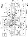
- Fig. 1
- eine Frontansicht eines Ausführungsbeispiels einer erfindungsgemäßen Werkzeugmaschine;
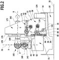
- Fig. 2
- einen Schnitt längs Linie 2-2 in
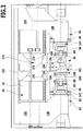
Fig. 1 ; - Fig. 3
- eine Draufsicht auf die Werkzeugmaschine gemäß
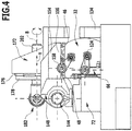
Fig. 1 ; - Fig. 4
- eine Seitenansicht von rechts der Werkzeugmaschine gemäß
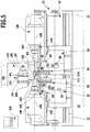
Fig. 1 ; - Fig. 5
- eine Ansicht ähnlich
Fig. 1 bei einer ersten Bearbeitungssituation; - Fig. 6
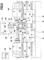
- eine Ansicht ähnlich
Fig. 1 bei einer zweiten Bearbeitungssituation; - Fig. 7
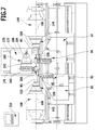
- eine Ansicht ähnlich
Fig. 1 bei einer dritten Bearbeitungssituation; - Fig. 8
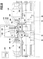
- eine Ansicht ähnlich
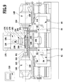
Fig. 1 bei einer vierten Bearbeitungssituation; - Fig. 9
- eine Ansicht ähnlich
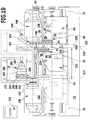
Fig. 1 bei einer fünften Bearbeitungssituation; - Fig. 10
- eine Ansicht ähnlich
Fig. 1 mit Darstellung einer Parkposition einer zweiten Werkzeugträgereinheit und den Bearbeitungsmöglichkeiten innerhalb eines Bewegungsbereichs der ersten Werkzeugträgereinheit; - Fig. 11
- eine Darstellung ähnlich
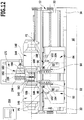
Fig. 1 einer Parkposition der ersten Werkzeugträgereinheit und der Bewegungsmöglichkeiten der zweiten Werkzeugträgereinheit und - Fig. 12
- eine Darstellung der ersten Werkzeugträgereinheit und der zweiten Werkzeugträgereinheit in einer Parkposition in einer Werkstückübergabestellung.
- Fig. 1
- a front view of an embodiment of a machine tool according to the invention;
- Fig. 2
- a section along line 2-2 in
Fig. 1 ; - Fig. 3
- a plan view of the machine tool according to
Fig. 1 ; - Fig. 4
- a side view from the right of the machine tool according to
Fig. 1 ; - Fig. 5
- a view similar
Fig. 1 at a first processing situation; - Fig. 6
- a view similar
Fig. 1 in a second processing situation; - Fig. 7
- a view similar
Fig. 1 in a third processing situation; - Fig. 8
- a view similar
Fig. 1 in a fourth processing situation; - Fig. 9
- a view similar
Fig. 1 in a fifth processing situation; - Fig. 10
- a view similar
Fig. 1 depicting a parking position of a second tool carrier unit and the processing options within a movement range of the first tool carrier unit; - Fig. 11
- a representation similar
Fig. 1 a parking position of the first tool carrier unit and the movement possibilities of the second tool carrier unit and - Fig. 12
- an illustration of the first tool carrier unit and the second tool carrier unit in a parking position in a workpiece transfer position.
Ein Ausführungsbeispiel einer erfindungsgemäßen Werkzeugmaschine 10, in diesem Fall einer Drehmaschine, umfasst ein als Ganzes mit 12 bezeichnetes Maschinengestell, welches seinerseits ein Maschinenbett 14 aufweist, welches über einem Untergestell 16 angeordnet ist, und zwar so, dass zwischen dem Untergestell 16 und dem Maschinenbett 14 ein Freiraum 18 vorliegt.An exemplary embodiment of a
Vorzugsweise wird dabei das Maschinenbett 14 endseitig durch Stützelemente 22 und 24 relativ zu dem Untergestell 16 abgestützt.Preferably, the
Das Maschinenbett 14 erstreckt sich dabei in einer Längsrichtung 26 zwischen den Stützelementen 22 und 24, so dass sich der Freiraum 18 vorzugsweise über die gesamte Länge des Maschinenbetts 14 zwischen den Stützelementen 22 und 24 erstreckt.The
Das Maschinenbett 14 umfasst seinerseits einen Maschinenbettkörper 32, der mit einer Unterseite 34 dem Untergestell 16 und somit auch einer Aufstellfläche 35 für das Untergestell 16 zugewandt ist.The
Von der Unterseite 34 erstrecken sich eine Frontseite 36 sowie eine Rückseite 38 des Maschinenbettkörpers 32 bis zu einer Oberseite 42 desselben, wobei die Oberseite 42 der Unterseite 34 gegenüberliegend und von dieser abgewandt ist.From the
Auf der Oberseite 42 sind parallel zu einer Z-Richtung und insbesondere auch parallel zur Längsrichtung 26 verlaufende und quer zur Z-Richtung und somit auch zur Längsrichtung 26 im Abstand voneinander angeordnete Linearführungen 44 und 46 vorgesehen, wobei die vordere Linearführung 44 nahe der Frontseite 36 auf einem Längssteg 48 des Maschinenbettkörpers 32 angeordnet ist, während die hintere Linearführung 46 nahe der Rückseite 38 auf der Oberseite 42 angeordnet ist.On the
An dem Längssteg 48, vorzugsweise unterhalb desselben ist an der Frontseite 36 eine sich in Z-Richtung erstreckende obere Linearführung 52 angeordnet.On the
Ferner schließt sich an den Längssteg 48 und zwar in Richtung zum Untergestell 16 oder zur Aufstellfläche 35 ein erster zurückgesetzter Bereich 54 der Frontseite 36 an und im Anschluss an den ersten zurückgesetzten Bereich 54 nahe des Übergangs zur Unterseite 34 ist ein zweiter zurückgesetzter Bereich 56 vorgesehen, in welchem eine untere zur Z-Achse parallele Linearführung 58 angeordnet ist.Furthermore, a first recessed
An der oberen Linearführung 52 und der unteren Linearführung 58, die sich auch parallel zur Längsrichtung 26, vorzugsweise über die gesamte Länge des Maschinenbetts 14 erstrecken, sind, wie in
Auf jeden Z-Schlitten 66 ist jeweils ein X-Schlitten 72 mit Linearführungen 74 geführt, die in X-Richtung, das heißt senkrecht zur Z-Richtung verlaufen, wobei die Linearführungen 74 vorzugsweise parallel zu einer Führungsebene 76 verlaufen, die sich parallel zur Z-Richtung erstreckt und vorzugsweise gegenüber einer Vertikalen um weniger als 30°, vorzugsweise weniger als 20° und noch besser weniger als 10° geneigt sind.On each Z-
Im einfachsten Fall verläuft die Führungsebene 76 parallel zu einer Vertikalen.In the simplest case, the
Zusätzlich zum X-Schlitten 72 umfassen die Schlittensysteme 62 und 64 noch einen Y-Schlitten 82, welcher an in parallel zu einer Y-Richtung verlaufenden Linearführungen 84 relativ zu dem X-Schlitten 72 geführt ist, wobei sich die Linearführungen 84 parallel zu einer Führungsebene 86 erstrecken, die senkrecht zur Z-Richtung verläuft.In addition to the X-carriage 72, the
Der jeweilige Y-Schlitten 82 des entsprechenden Schlittensystems 62 oder 64 trägt, wie beispielsweise in
Dabei weist der jeweilige Revolverkopf 98 Werkzeugaufnahmen 104, in welche Werkzeuge 106 einsetzbar sind.In this case, the
Die Schlittensystem 62 und 64 sowie die auf diesen angeordneten Werkzeugträgereinheiten 92 und 94 sind vorzugsweise spiegelsymmetrisch zueinander ausgebildet, wobei die Revolverköpfe 98 der Werkzeugträgereinheiten 92 bzw. 94 einander zugewandt angeordnet sind und vorzugsweise über einander zugewandten Randbereichen 112 bzw. 114 der Schlittensystem 62 bzw. 64 stehen.The
Die Schlittensysteme 62 und 64 sind durch bekannte Linearantriebssysteme sowohl in Z-, als auch in X-, und in Y-Richtung verfahrbar, wobei beispielsweise entweder elektrische Linearmotoren oder mechanische Linearantriebe, wie beispielsweise Kugelrollspindeln zum Einsatz kommen können.The
Bei dem dargestellten Ausführungsbeispiel ist der Z-Schlitten 66 jedes Schlittensystems 62, 64 durch mittels Antriebsmotoren 124 antreibbaren Vorschubspindeln 122 bewegbar, die mit an den Z-Schlitten 66 auf einander abgewandten Seiten sitzenden Spindelmuttern 126 zusammenwirken.In the illustrated embodiment, the Z-
Ferner sind die Vorschubspindeln 122 an ihren einander zugewandten Enden in einer gemeinsamen Lagereinheit 128 am Maschinenbettkörper 32 drehbar gelagert und außerdem an ihren durch die Antriebsmotoren 124 angetriebenen, einander abgewandten Enden in Lagereinheiten 129 drehbar und axial unverschiebbar gelagert.Further, the feed screws 122 are rotatably mounted at their mutually facing ends in a
Die Versorgung der Schlittensysteme 62 und 64 erfolgt vorzugsweise über einen den Freiraum 18 durchsetzenden Kabelkanal 132, der mit einer Schleppkettenanordnung 134, die längs der Rückseite 38 verläuft, zusammenwirkt.The supply of the
Der Kabelkanal 132 ist dabei fest mit dem jeweiligen Z-Schlitten 66 des jeweiligen Schlittensystems 62 und 64 verbunden und bewegt sich zusammen mit diesem in der Z-Richtung.The
Zur Aufnahme von zu bearbeitenden Werkstücken W1 und W2 ist die Werkzeugmaschine mit Werkstückspindeleinheiten 142 und 144 versehen, die jeweils in Spindelträgern 146 bzw. 148 gehalten sind, wobei beide Spindelträger 146, 148, wie in
Beispielsweise ist die erste Werkstückspindeleinheit 142 relativ zum Maschinenbettkörper 32 stationär angeordnet, so dass in diesem Fall der Spindelträger 146 mit einem Montageabschnitt 152 stationär an der Oberseite 42 des Maschinenbettkörpers 32 fixiert ist.For example, the first
Im Gegensatz dazu ist der Spindelträger 148 in der Z-Richtung bewegbar und daher sitzt ein Montageabschnitt 154 des zweiten Spindelträgers 148 auf einem durch einen Vorschubspindelantrieb 158 bewegbaren Z-Schlitten 156, der an den Linearführungen 44 und 46, die sich in Z-Richtung erstrecken, relativ zum Maschinenbettkörper 32 fixiert ist (
Somit ist die zweite Werkstückspindeleinheit 144 in der Z-Richtung relativ zur ersten Werkstückspindeleinheit 142 und somit auch relativ zum Maschinenbettkörper 32 in der Z-Richtung gesteuert verschiebbar.Thus, the second
Es besteht aber auch die Möglichkeit die erste Werkstückspindeleinheit 142 mit dem Montageabschnitt 152 auf einem Z-Schlitten anzuordnen und diesen ebenfalls durch die Linearführungen 44 und 46 in Z-Richtung bewegbar am Maschinenbettkörper 32 zu führen.But it is also possible to arrange the first
Jede der Werkstückspindeleinheiten 142 und 144 ist mit einer Werkstückaufnahme 162 bzw. 164 versehen, in welcher die Werkstücke W1 und W2 zur Bearbeitung aufgenommen werden.Each of the
Ferner ist jede der Werkstückaufnahmen 162, 164 durch die jeweiligen Werkstückspindeleinheiten 142 bzw. 144 um eine jeweilige Spindelachse 166 bzw. 168 drehbar gelagert und auch durch einen nicht dargestellten Spindelantrieb, beispielsweise einen integrierten Hohlwellenmotor, um die jeweilige Spindelachse 166 bzw. 168 rotierend antreibbar.Further, each of the
Dabei sind die Spindelachsen 166 und 168 im einfachsten Fall koaxial zueinander ausgerichtet, so dass zur Bearbeitung eines Werkstücks W1 auf der Vorderseite, beispielsweise in der ersten Werkstückspindeleinheit 142 das Werkzeug als Werkstück W2 in die zweite Werkstückspindeleinheit 144 zur Bearbeitung auf der Rückseite in einer Werkstückübergabeposition übergebbar ist.In the simplest case, the spindle axes 166 and 168 are aligned coaxially with each other, so that for machining a workpiece W1 on the front side, for example in the first
Hierzu ist bei dem zeichnerisch dargestellten Ausführungsbeispiel die zweite Werkstückspindeleinheit 144 auf die erste Werkstückspindeleinheit 142 in Z-Richtung zu bewegbar, so dass das Werkstück W1 von der ersten Werkstückaufnahme 162 in die zweite Werkstückaufnahme 164 übergeben werden kann.For this purpose, in the exemplary embodiment illustrated, the second
Bei der beschriebenen Lösung liegen insbesondere die unteren Werkzeugträgereinheiten 92 und 94 und die unteren Schlittensysteme 62, 64 unterhalb einer durch die Spindelachsen 166, 168 in der Werkstückübergabeposition hindurch verlaufenden horizontalen Ebene 169.In the described solution, in particular, the lower
Bei dem dargestellten Ausführungsbeispiel nicht realisiert, jedoch denkbar ist eine zusätzliche Verfahrbarkeit einer der Werkstückspindeleinheiten 142, 144, beispielsweise der zweiten Werkstückspindeleinheit 144, in Richtung der X-Achse in eine weitere Bearbeitungsposition, so dass beispielsweise die zweite Spindelachse 168 in dieser Bearbeitungsposition zwar parallel zur ersten Spindelachse 166 ausgerichtet ist, jedoch nicht koaxial.In the illustrated embodiment not realized, but conceivable is an additional movability of one of the
Auf den Linearführungen 44 und 46, die auf der Oberseite 42 des Maschinenbettkörpers 32 angeordnet sind, ist weiterhin noch ein als Ganzes mit 172 bezeichnetes Schlittensystem angeordnet, welches einen an den Linearführungen 44 und 46 geführten Z-Schlitten 174 und einen an dem Z-Schlitten 174 durch parallel zur X-Richtung verlaufende Linearführungen 176 geführten X-Schlitten 178 aufweist.On the
An dem X-Schlitten 178 ist eine Pinole 202 des Schlittensystems 172 in einer Y-Richtung verfahrbar und um eine zur Y-Richtung parallele B-Achse drehbar geführt.On the X-carriage 178 a
Die Pinole 202 trägt eine als Ganzes mit 182 bezeichnete Werkzeugträgereinheit, die einerseits eine Frässpindel 184 umfasst, die um eine Frässpindelachse 186 drehbar ist, sowie einen der Frässpindel 184 gegenüberliegende angeordneten Werkzeugrevolver 188 aufweist, der ein Revolvergehäuse 192 umfasst, an welchem ein Revolverkopf 194 um eine Revolverachse 196 drehbar gelagert ist.The
Vorzugsweise verlaufen dabei die Revolverachse 196 und die Frässpindelachse 186 koaxial zueinander und senkrecht zu der Y/B-Achse, wobei die Werkzeugträgereinheit 182 durch die Pinole 202 entlang der Y-Achse bewegbar und um die B-Achse drehbar ist.Preferably, the
Vorzugsweise ist der Revolverkopf 194 so ausgebildet, dass dieser radial zur Revolverachse 196 verlaufende Werkzeugaufnahmen 204 aufweist, in welche Bearbeitungswerkzeuge 206 einsetzbar sind.Preferably, the
Zum Betrieb der erfindungsgemäßen Werkzeugmaschine ist eine Steuerung 210 vorgesehen, welche die Bewegungen der unteren Werkzeugträgereinheiten 92 und 94 in den X-, Y- und Z-Richtungen steuert, die Bewegungen der oberen Werkezugträgereinheit 182 in den X-, Y- und Z-Richtungen und um die B-Achse steuert, die Drehungen Revolverköpfe 98 und 194 um die entsprechenden Revolverachsen 102 und 196 steuert, Antriebe der Werkstückspindeleinheiten 142 und 144 steuert und die Bewegungen des zweiten Spindelträgers 148 in Z-Richtung steuert.For operating the machine tool according to the invention, a
Mit der erfindungsgemäßen Werkzeugmaschine 10 sind die unterschiedlichsten Bearbeitungen durchführbar.With the
Beispielsweise sind die Werkzeuge 106 der beiden Werkzeugträgereinheiten 92 und 94 sowie das Bearbeitungswerkzeug 206 der Werkzeugträgereinheit 182 an dem ersten Werkstück W1 einsetzbar, wenn dies in der Werkstückaufnahme 162 der ersten Werkstückspindeleinheit 142 gehalten und um die erste Spindelachse 166 gegebenenfalls rotierend angetrieben ist (
In gleicher Weise wie in
Es besteht aber auch die Möglichkeit, wie in
Wie in den
Schließlich besteht auch noch die Möglichkeit, wie in
Bei allen beispielhaften, in den
Um beispielsweise mit dem Werkzeug 106 der ersten Werkzeugträgereinheit 92 im gesamten Bearbeitungsbereich 212 ein Werkstück, beispielsweise ein Wellenteil WT, das sowohl von der Werkstückaufnahme 162 als auch von der Werkstückaufnahme 164 und somit von der ersten Werkstückspindel 142 und von der zweiten Werkstückspindel 144 gleichzeitig gehalten und angetrieben ist, bearbeiten zu können, und somit den gesamten Bearbeitungsbereich 212 mit diesem Werkzeug 106 durchfahren zu können, ist wie in
In dieser Parkposition P2 der zweiten Werkzeugträgereinheit 94 mit dem zweiten Schlittensystem 64 steht das zweite Schlittensystem 64 mit der zweiten Werkzeugträgereinheit 94 vorzugsweise in Z-Richtung gesehen in einem Z-Positionsbereich, welcher ungefähr dem Z-Positionsbereich der zweiten Spindeleinheit 144 entspricht, so dass die zweite Werkzeugträgereinheit 94 in einem Abstand AB2 von der zweiten Begrenzungsebene 216 positioniert ist, um ein vollständiges Überfahren des Bearbeitungsbereichs 212 durch das Werkzeug 106 der ersten Werkzeugträgereinheit 92 zu gewährleisten, ohne dass eine Kollision zwischen der ersten Werkzeugträgereinheit 92 und der zweiten Werkzeugträgereinheit 94 auftritt.In this parking position P2 of the second
Vorzugsweise entspricht der Abstand AB2 der zweiten Werkzeugträgereinheit 94 von der zweiten Begrenzungsebene 216 mindestens einem Abstand A1 der Werkzeugaufnahme 104 des Werkzeugs 106 der ersten Werkzeugträgereinheit 92 von einer in Z-Richtung der zweiten Werkzeugträgereinheit 94 nächstliegenden und die erste Werkzeugträgereinheit 92 oder das erste Schlittensystems 62 tangierenden Systemgrenzebene 232, die beispielsweise den Revolverkopf 98 stirnseitig tangiert, wenn dieser in Richtung der zweiten Werkzeugträgereinheit 94 über das erste Schlittensystem 62 übersteht.The distance AB2 of the second
Um bei einer Bewegung der zweiten Werkstückspindeleinheit 144 in Z-Richtung die Position des in der Parkposition P2 stehenden zweiten Schlittensystems 64 mit der zweiten Werkzeugträgereinheit 94 relativ zur Werkstückspindeleinheit aufrecht zu erhalten, sieht die Steuerung 210 in diesem Fall einer Kopplung der Z-Bewegung des Z-Schlittens 156 des Spindelträger 154 und der Z-Bewegung des Z-Schlittens 66 des Schlittensystems 64 vor, so dass beide Z-Schlitten 156 und 66 synchron miteinander verfahren.In order to maintain the position of the
In gleicher Weise kann, wie in
Vorzugsweise entspricht auch in diesem Fall der Abstand AB1 der ersten Werkzeugträgereinheit 92 von der ersten Begrenzungsebene 214 mindestens einem Abstand A2 der Werkzeugaufnahme 104 der zweiten Werkzeugträgereinheit 94 von einer in Z-Richtung der gegenüberliegenden Werkzeugträgereinheit 92 nächstliegenden und die zweite Werkzeugträgereinheit 94 oder die zweite Schlitteneinheit 64 tangierenden Systemgrenzebene 234, die beispielsweise den Revolverkopf 98 stirnseitig tangiert, wenn dieser in Richtung der ersten Werkzeugträgereinheit 92 über das zweite Schlittensystem 64 übersteht.Also in this case, the distance AB1 of the first
Wie in
Insbesondere stehen das jeweilige untere Schlittensystem 62, 64 und die jeweilige untere Werkzeugträgereinheit 92, 94 in der jeweiligen Parkposition P1, P2 zwischen zwei Spindelendebenen 236, 238 der jeweiligen Werkstückspindeleinheit 142, 144, die durch die jeweils in Z-Richtung einander gegenüberliegenden Enden der Werkstückspindeleinheiten 142, 144 festgelegt sind und die senkrecht zu der jeweiligen Spindelachse 166, 168 verlaufen.In particular, the respective
Claims (11)
- Machine tool with a machine frame (12) comprising a machine bed (14) with a machine bed member (32) extending in a longitudinal direction (26) and having an underside (34) facing an installation surface (35) of the machine tool, an upper side (42) arranged so as to be located opposite the underside (34) and facing away from the underside (34) as well as a front side (36) extending transversely to the underside (34) between the underside (34) and the upper side (42),
comprising two workpiece spindle units (142, 144) arranged on the machine bed (14), said spindle units being held by spindle carriers (146, 148) and each of them having a workpiece receptacle (162, 164) rotatable about a respective spindle axis (166, 168), wherein the workpiece spindle units (142, 144) are arranged on the machine bed (14) in such a manner that the spindle axes (166, 168) are aligned coaxially to one another such that a workpiece is transferrable in a workpiece transfer position for machining on the front side and the rear side, wherein the spindle carriers (146, 148) holding the workpiece spindle units (142, 144) are held on the upper side (42) of the machine bed member (32) and comprising at least one lower tool carrier unit (92, 94) arranged on the machine bed (14) and supported by a lower slide system (62, 64), wherein the at least one lower slide system (62, 64) is arranged on the front side (36) of the machine bed member (32) and is guided on the machine bed member (32) in linear guides (52, 58) extending in a Z direction, wherein in the workpiece transfer position the spindle axes (166, 168) are located in an X/Z plane extending at a distance from the front side (36) and at a distance in front of the front side (36) of the machine bed member (32),
characterized in that one of the spindle carriers (146, 148) is fixed stationarily on the upper side (42) of the machine bed member (32), that at least two lower tool carrier units (92, 94) each supported by a lower slide system (62, 64) are provided on the machine bed (14), that the at least two lower slide systems (62, 64) are movable with the respective lower tool carrier unit (92, 94) in the Z direction to such an extent that they reach a parking position (P1, P2) outside a machining area (212), said area extending in the Z direction between limiting planes (214, 216) extending at right angles to the respective spindle axes (166, 168) and bordering on an end side (222, 224) of the workpiece receptacles (162, 164), that the at least two lower slide systems (62, 64) are guided on the machine bed member (32) for movement in the Z direction in such a manner that in the case of every possible extension of the machining area (212) in the Z direction the tools (106) of the respective lower tool carrier unit (92, 94) are deployable within the entire machining area (212). - Machine tool as defined in claim 1, characterized in that in the workpiece transfer position the spindle axes (166, 168) are located in an X/Z plane running parallel to the Z direction and inclined through an angle of 30° or less in relation to the vertical.
- Machine tool as defined in any one of the preceding claims, characterized in that at least one lower slide system (62, 64) and, in particular, the lower tool carrier unit (92, 94), as well, are located beneath a horizontal plane (169) extending through the spindle axes (166, 168) in the workpiece transfer position.
- Machine tool as defined in any one of the preceding claims, characterized in that in the parking position (P1, P2) the at least one lower slide system (62, 64) and the respective lower tool carrier unit (92, 94) supported by it are positionable at least at a distance (AB1, AB2) from the respective limiting plane (214, 216) and outside the machining area (212).
- Machine tool as defined in any one of the preceding claims, characterized in that the slide system (62, 64) located in the parking position (P1, P2) and the respective tool carrier unit (92, 94) supported by it are located in the parking position (P1, P2) at a distance (AB1, AB2) from the closest limiting plane (214, 216) of the machining space (212) corresponding at least to a distance (A1, A2) of a tool receptacle (104) from a system boundary plane (232, 234) extending parallel to the limiting plane (214, 216), the position of said system boundary plane being defined by a maximum extension of the respectively other one of the slide systems (62, 64) with the respective tool carrier unit (92, 94) supported by it, where applicable with the tools, in the direction of the limiting plane (214, 216).
- Machine tool as defined in any one of the preceding claims, characterized in that the respective lower tool carrier unit (92, 94) is positionable in a parking position (P1, P2) located between two spindle end planes (236, 238) defined by the respective workpiece spindle unit (142, 144), said planes extending transversely to the respective spindle axis (166, 168) and being determined in the Z direction by ends of the workpiece spindle units (142, 144) located opposite one another.
- Machine tool as defined in any one of the preceding claims, characterized in that tools (106) of the respective lower tool carrier units (92, 94) are arranged above edge areas (112, 114) of the respective lower slide systems (62, 64) arranged so as to face one another.
- Machine tool as defined in any one of the preceding claims, characterized in that the respective lower tool carrier unit (92, 94) is movable in the Z direction and in the X direction relative to the machine bed member (32) by the respective lower slide system (62, 64).
- Machine tool as defined in claim 8, characterized in that the respective lower tool carrier unit (92, 94) is movable, in addition, in the Y direction by the respective slide system (62, 64).
- Machine tool as defined in any one of the preceding claims, characterized in that the respective lower tool carrier unit (92, 94) is positionable in the X direction and/or the Y direction by the respective lower slide system (62, 64) in such a manner that it is movable in the Z direction past the workpiece receptacle (162, 164) of the respective workpiece spindle unit (142, 144).
- Machine tool as defined in any one of the preceding claims, characterized in that the respective lower tool carrier unit (92, 94) is positionable in the X direction and/or in the Y direction by the respective lower slide system (62, 64) in such a manner that it is movable in the Z direction past the respective workpiece spindle unit (146, 148).
Priority Applications (1)
| Application Number | Priority Date | Filing Date | Title |
|---|---|---|---|
| PL15183545T PL2995419T3 (en) | 2014-09-12 | 2015-09-02 | Machine tool |
Applications Claiming Priority (1)
| Application Number | Priority Date | Filing Date | Title |
|---|---|---|---|
| DE102014113204.1A DE102014113204A1 (en) | 2014-09-12 | 2014-09-12 | machine tool |
Publications (2)
| Publication Number | Publication Date |
|---|---|
| EP2995419A1 EP2995419A1 (en) | 2016-03-16 |
| EP2995419B1 true EP2995419B1 (en) | 2019-07-17 |
Family
ID=54056129
Family Applications (1)
| Application Number | Title | Priority Date | Filing Date |
|---|---|---|---|
| EP15183545.1A Active EP2995419B1 (en) | 2014-09-12 | 2015-09-02 | Machine tool |
Country Status (6)
| Country | Link |
|---|---|
| EP (1) | EP2995419B1 (en) |
| CN (1) | CN105414991B (en) |
| DE (1) | DE102014113204A1 (en) |
| ES (1) | ES2745118T3 (en) |
| HU (1) | HUE046141T2 (en) |
| PL (1) | PL2995419T3 (en) |
Families Citing this family (2)
| Publication number | Priority date | Publication date | Assignee | Title |
|---|---|---|---|---|
| JP7195305B2 (en) * | 2018-03-30 | 2022-12-23 | シチズン時計株式会社 | Machine Tools |
| CN110076588B (en) * | 2019-05-31 | 2020-05-08 | 重庆宏钢数控机床有限公司 | Special machine tool |
Citations (7)
| Publication number | Priority date | Publication date | Assignee | Title |
|---|---|---|---|---|
| JPH05345203A (en) | 1992-06-15 | 1993-12-27 | Mori Seiki Co Ltd | Headstock clamping device for facing spindle lathe |
| DE19904859A1 (en) | 1999-02-05 | 2000-08-17 | Gildemeister Drehmaschinen Gmb | Automatic turret lathe with two spindles working in vertical position with workpiece holding unit located below |
| DE19911156A1 (en) | 1999-03-12 | 2000-09-21 | Weisser Soehne J G | Rotary lathe for finishing longer length workpieces has mechanically independent cross slides with one supporting head stock and other supporting tail stock |
| EP1193027A2 (en) | 2000-09-29 | 2002-04-03 | Traub Drehmaschinen GmbH | Lathe |
| EP1155764B1 (en) | 1999-10-28 | 2007-12-12 | Nakamura-Tome Precision Ind. Co., Ltd. | Combined nc lathe |
| DE112005000228B4 (en) | 2004-03-12 | 2010-09-30 | Hessapp Gmbh | Lathe, in particular vertical lathe and method for parallel machining of two workpieces on this lathe |
| DE102012107295A1 (en) | 2012-08-08 | 2014-02-13 | Index-Werke Gmbh & Co. Kg Hahn & Tessky | Machine tool for processing workpiece, has workpiece spindle movement system which guides workpiece spindle unit to guide portion on machine base element which is not overlapped with another guide portion |
Family Cites Families (6)
| Publication number | Priority date | Publication date | Assignee | Title |
|---|---|---|---|---|
| DE10116994A1 (en) | 2001-04-05 | 2002-10-17 | Index Werke Kg Hahn & Tessky | machine tool |
| EP1270145A3 (en) * | 2001-06-22 | 2004-02-11 | Traub Drehmaschinen GmbH | Machine tool with rotatable multi-tool holder |
| DE102006023030A1 (en) * | 2006-05-10 | 2007-11-15 | Traub Drehmaschinen Gmbh & Co. Kg | machine tool |
| DE102010042281A1 (en) * | 2010-07-12 | 2012-01-12 | Index-Werke Gmbh & Co. Kg Hahn & Tessky | Spindles |
| DE102011077571B4 (en) * | 2011-06-15 | 2014-06-18 | Gildemeister Italiana S.P.A. | MACHINE TOOL |
| DE102013201542A1 (en) * | 2013-01-30 | 2014-07-31 | Mag Ias Gmbh | Machine tool for machining workpieces |
-
2014
- 2014-09-12 DE DE102014113204.1A patent/DE102014113204A1/en not_active Ceased
-
2015
- 2015-09-02 PL PL15183545T patent/PL2995419T3/en unknown
- 2015-09-02 HU HUE15183545A patent/HUE046141T2/en unknown
- 2015-09-02 ES ES15183545T patent/ES2745118T3/en active Active
- 2015-09-02 EP EP15183545.1A patent/EP2995419B1/en active Active
- 2015-09-08 CN CN201510566595.1A patent/CN105414991B/en active Active
Patent Citations (7)
| Publication number | Priority date | Publication date | Assignee | Title |
|---|---|---|---|---|
| JPH05345203A (en) | 1992-06-15 | 1993-12-27 | Mori Seiki Co Ltd | Headstock clamping device for facing spindle lathe |
| DE19904859A1 (en) | 1999-02-05 | 2000-08-17 | Gildemeister Drehmaschinen Gmb | Automatic turret lathe with two spindles working in vertical position with workpiece holding unit located below |
| DE19911156A1 (en) | 1999-03-12 | 2000-09-21 | Weisser Soehne J G | Rotary lathe for finishing longer length workpieces has mechanically independent cross slides with one supporting head stock and other supporting tail stock |
| EP1155764B1 (en) | 1999-10-28 | 2007-12-12 | Nakamura-Tome Precision Ind. Co., Ltd. | Combined nc lathe |
| EP1193027A2 (en) | 2000-09-29 | 2002-04-03 | Traub Drehmaschinen GmbH | Lathe |
| DE112005000228B4 (en) | 2004-03-12 | 2010-09-30 | Hessapp Gmbh | Lathe, in particular vertical lathe and method for parallel machining of two workpieces on this lathe |
| DE102012107295A1 (en) | 2012-08-08 | 2014-02-13 | Index-Werke Gmbh & Co. Kg Hahn & Tessky | Machine tool for processing workpiece, has workpiece spindle movement system which guides workpiece spindle unit to guide portion on machine base element which is not overlapped with another guide portion |
Also Published As
| Publication number | Publication date |
|---|---|
| CN105414991B (en) | 2019-11-12 |
| CN105414991A (en) | 2016-03-23 |
| HUE046141T2 (en) | 2020-02-28 |
| EP2995419A1 (en) | 2016-03-16 |
| DE102014113204A1 (en) | 2016-03-17 |
| ES2745118T3 (en) | 2020-02-27 |
| PL2995419T3 (en) | 2019-12-31 |
Similar Documents
| Publication | Publication Date | Title |
|---|---|---|
| EP2623255B1 (en) | Universal machine tool with chip collection area | |
| EP1193027B1 (en) | Lathe | |
| EP1118428B2 (en) | Lathe | |
| EP3535092B1 (en) | Honing machine having multiple workstations | |
| EP1409182B1 (en) | Machine tool | |
| EP1525065B1 (en) | Machine tool with two workpiece spindles | |
| EP2021149B1 (en) | Machine tool | |
| EP3075490B1 (en) | Machining unit | |
| WO2016174133A1 (en) | Machining system for aircraft structural components | |
| EP1511596B1 (en) | Multi-spindle lathe | |
| EP1574273B1 (en) | Lathe | |
| EP2995419B1 (en) | Machine tool | |
| EP0928235A1 (en) | Machine tool for cutting processes with a horizontally lodged work spindle | |
| EP3624988B1 (en) | Machine-tool | |
| EP1074333B1 (en) | Lathe with two tool carrier systems | |
| EP2995418A1 (en) | Machine tool | |
| AT521951B1 (en) | Machine tool | |
| EP1752241B1 (en) | Turning machine | |
| EP2200779A2 (en) | Lathe | |
| DE19607883A1 (en) | Lathe with several spindles | |
| DE202020005231U1 (en) | Machine tool | |
| DE4022706C2 (en) | Lathe | |
| WO2012168489A1 (en) | Machine tool and method for a machine tool | |
| WO2010119087A2 (en) | Lathe | |
| EP3274127B1 (en) | Advancing device and vertical lathe having same |
Legal Events
| Date | Code | Title | Description |
|---|---|---|---|
| PUAI | Public reference made under article 153(3) epc to a published international application that has entered the european phase |
Free format text: ORIGINAL CODE: 0009012 |
|
| AK | Designated contracting states |
Kind code of ref document: A1 Designated state(s): AL AT BE BG CH CY CZ DE DK EE ES FI FR GB GR HR HU IE IS IT LI LT LU LV MC MK MT NL NO PL PT RO RS SE SI SK SM TR |
|
| AX | Request for extension of the european patent |
Extension state: BA ME |
|
| 17P | Request for examination filed |
Effective date: 20160914 |
|
| RBV | Designated contracting states (corrected) |
Designated state(s): AL AT BE BG CH CY CZ DE DK EE ES FI FR GB GR HR HU IE IS IT LI LT LU LV MC MK MT NL NO PL PT RO RS SE SI SK SM TR |
|
| STAA | Information on the status of an ep patent application or granted ep patent |
Free format text: STATUS: EXAMINATION IS IN PROGRESS |
|
| 17Q | First examination report despatched |
Effective date: 20170720 |
|
| GRAP | Despatch of communication of intention to grant a patent |
Free format text: ORIGINAL CODE: EPIDOSNIGR1 |
|
| STAA | Information on the status of an ep patent application or granted ep patent |
Free format text: STATUS: GRANT OF PATENT IS INTENDED |
|
| INTG | Intention to grant announced |
Effective date: 20190123 |
|
| GRAS | Grant fee paid |
Free format text: ORIGINAL CODE: EPIDOSNIGR3 |
|
| GRAA | (expected) grant |
Free format text: ORIGINAL CODE: 0009210 |
|
| STAA | Information on the status of an ep patent application or granted ep patent |
Free format text: STATUS: THE PATENT HAS BEEN GRANTED |
|
| AK | Designated contracting states |
Kind code of ref document: B1 Designated state(s): AL AT BE BG CH CY CZ DE DK EE ES FI FR GB GR HR HU IE IS IT LI LT LU LV MC MK MT NL NO PL PT RO RS SE SI SK SM TR |
|
| REG | Reference to a national code |
Ref country code: GB Ref legal event code: FG4D Free format text: NOT ENGLISH |
|
| REG | Reference to a national code |
Ref country code: CH Ref legal event code: EP Ref country code: CH Ref legal event code: NV Representative=s name: KIRKER AND CIE S.A., CH |
|
| REG | Reference to a national code |
Ref country code: IE Ref legal event code: FG4D Free format text: LANGUAGE OF EP DOCUMENT: GERMAN |
|
| REG | Reference to a national code |
Ref country code: DE Ref legal event code: R096 Ref document number: 502015009647 Country of ref document: DE |
|
| REG | Reference to a national code |
Ref country code: AT Ref legal event code: REF Ref document number: 1155399 Country of ref document: AT Kind code of ref document: T Effective date: 20190815 |
|
| REG | Reference to a national code |
Ref country code: NL Ref legal event code: FP |
|
| REG | Reference to a national code |
Ref country code: SE Ref legal event code: TRGR |
|
| REG | Reference to a national code |
Ref country code: SK Ref legal event code: T3 Ref document number: E 32355 Country of ref document: SK |
|
| REG | Reference to a national code |
Ref country code: LT Ref legal event code: MG4D |
|
| PG25 | Lapsed in a contracting state [announced via postgrant information from national office to epo] |
Ref country code: HR Free format text: LAPSE BECAUSE OF FAILURE TO SUBMIT A TRANSLATION OF THE DESCRIPTION OR TO PAY THE FEE WITHIN THE PRESCRIBED TIME-LIMIT Effective date: 20190717 Ref country code: LT Free format text: LAPSE BECAUSE OF FAILURE TO SUBMIT A TRANSLATION OF THE DESCRIPTION OR TO PAY THE FEE WITHIN THE PRESCRIBED TIME-LIMIT Effective date: 20190717 Ref country code: NO Free format text: LAPSE BECAUSE OF FAILURE TO SUBMIT A TRANSLATION OF THE DESCRIPTION OR TO PAY THE FEE WITHIN THE PRESCRIBED TIME-LIMIT Effective date: 20191017 Ref country code: PT Free format text: LAPSE BECAUSE OF FAILURE TO SUBMIT A TRANSLATION OF THE DESCRIPTION OR TO PAY THE FEE WITHIN THE PRESCRIBED TIME-LIMIT Effective date: 20191118 Ref country code: BG Free format text: LAPSE BECAUSE OF FAILURE TO SUBMIT A TRANSLATION OF THE DESCRIPTION OR TO PAY THE FEE WITHIN THE PRESCRIBED TIME-LIMIT Effective date: 20191017 Ref country code: FI Free format text: LAPSE BECAUSE OF FAILURE TO SUBMIT A TRANSLATION OF THE DESCRIPTION OR TO PAY THE FEE WITHIN THE PRESCRIBED TIME-LIMIT Effective date: 20190717 |
|
| REG | Reference to a national code |
Ref country code: ES Ref legal event code: FG2A Ref document number: 2745118 Country of ref document: ES Kind code of ref document: T3 Effective date: 20200227 |
|
| PG25 | Lapsed in a contracting state [announced via postgrant information from national office to epo] |
Ref country code: IS Free format text: LAPSE BECAUSE OF FAILURE TO SUBMIT A TRANSLATION OF THE DESCRIPTION OR TO PAY THE FEE WITHIN THE PRESCRIBED TIME-LIMIT Effective date: 20191117 Ref country code: RS Free format text: LAPSE BECAUSE OF FAILURE TO SUBMIT A TRANSLATION OF THE DESCRIPTION OR TO PAY THE FEE WITHIN THE PRESCRIBED TIME-LIMIT Effective date: 20190717 Ref country code: GR Free format text: LAPSE BECAUSE OF FAILURE TO SUBMIT A TRANSLATION OF THE DESCRIPTION OR TO PAY THE FEE WITHIN THE PRESCRIBED TIME-LIMIT Effective date: 20191018 Ref country code: AL Free format text: LAPSE BECAUSE OF FAILURE TO SUBMIT A TRANSLATION OF THE DESCRIPTION OR TO PAY THE FEE WITHIN THE PRESCRIBED TIME-LIMIT Effective date: 20190717 Ref country code: LV Free format text: LAPSE BECAUSE OF FAILURE TO SUBMIT A TRANSLATION OF THE DESCRIPTION OR TO PAY THE FEE WITHIN THE PRESCRIBED TIME-LIMIT Effective date: 20190717 |
|
| REG | Reference to a national code |
Ref country code: HU Ref legal event code: AG4A Ref document number: E046141 Country of ref document: HU |
|
| REG | Reference to a national code |
Ref country code: DE Ref legal event code: R026 Ref document number: 502015009647 Country of ref document: DE |
|
| PLBI | Opposition filed |
Free format text: ORIGINAL CODE: 0009260 |
|
| PG25 | Lapsed in a contracting state [announced via postgrant information from national office to epo] |
Ref country code: EE Free format text: LAPSE BECAUSE OF FAILURE TO SUBMIT A TRANSLATION OF THE DESCRIPTION OR TO PAY THE FEE WITHIN THE PRESCRIBED TIME-LIMIT Effective date: 20190717 Ref country code: DK Free format text: LAPSE BECAUSE OF FAILURE TO SUBMIT A TRANSLATION OF THE DESCRIPTION OR TO PAY THE FEE WITHIN THE PRESCRIBED TIME-LIMIT Effective date: 20190717 Ref country code: RO Free format text: LAPSE BECAUSE OF FAILURE TO SUBMIT A TRANSLATION OF THE DESCRIPTION OR TO PAY THE FEE WITHIN THE PRESCRIBED TIME-LIMIT Effective date: 20190717 |
|
| 26 | Opposition filed |
Opponent name: WFL MILLTURN TECHNOLOGIES GMBH & CO. KG Effective date: 20200417 |
|
| PG25 | Lapsed in a contracting state [announced via postgrant information from national office to epo] |
Ref country code: MC Free format text: LAPSE BECAUSE OF FAILURE TO SUBMIT A TRANSLATION OF THE DESCRIPTION OR TO PAY THE FEE WITHIN THE PRESCRIBED TIME-LIMIT Effective date: 20190717 Ref country code: SM Free format text: LAPSE BECAUSE OF FAILURE TO SUBMIT A TRANSLATION OF THE DESCRIPTION OR TO PAY THE FEE WITHIN THE PRESCRIBED TIME-LIMIT Effective date: 20190717 Ref country code: IS Free format text: LAPSE BECAUSE OF FAILURE TO SUBMIT A TRANSLATION OF THE DESCRIPTION OR TO PAY THE FEE WITHIN THE PRESCRIBED TIME-LIMIT Effective date: 20200224 |
|
| PLAX | Notice of opposition and request to file observation + time limit sent |
Free format text: ORIGINAL CODE: EPIDOSNOBS2 |
|
| PG2D | Information on lapse in contracting state deleted |
Ref country code: IS |
|
| PG25 | Lapsed in a contracting state [announced via postgrant information from national office to epo] |
Ref country code: LU Free format text: LAPSE BECAUSE OF NON-PAYMENT OF DUE FEES Effective date: 20190902 |
|
| REG | Reference to a national code |
Ref country code: BE Ref legal event code: MM Effective date: 20190930 |
|
| PG25 | Lapsed in a contracting state [announced via postgrant information from national office to epo] |
Ref country code: SI Free format text: LAPSE BECAUSE OF FAILURE TO SUBMIT A TRANSLATION OF THE DESCRIPTION OR TO PAY THE FEE WITHIN THE PRESCRIBED TIME-LIMIT Effective date: 20190717 Ref country code: BE Free format text: LAPSE BECAUSE OF NON-PAYMENT OF DUE FEES Effective date: 20190930 |
|
| PLBB | Reply of patent proprietor to notice(s) of opposition received |
Free format text: ORIGINAL CODE: EPIDOSNOBS3 |
|
| PG25 | Lapsed in a contracting state [announced via postgrant information from national office to epo] |
Ref country code: CY Free format text: LAPSE BECAUSE OF FAILURE TO SUBMIT A TRANSLATION OF THE DESCRIPTION OR TO PAY THE FEE WITHIN THE PRESCRIBED TIME-LIMIT Effective date: 20190717 |
|
| PG25 | Lapsed in a contracting state [announced via postgrant information from national office to epo] |
Ref country code: MT Free format text: LAPSE BECAUSE OF FAILURE TO SUBMIT A TRANSLATION OF THE DESCRIPTION OR TO PAY THE FEE WITHIN THE PRESCRIBED TIME-LIMIT Effective date: 20190717 |
|
| PLCK | Communication despatched that opposition was rejected |
Free format text: ORIGINAL CODE: EPIDOSNREJ1 |
|
| APBM | Appeal reference recorded |
Free format text: ORIGINAL CODE: EPIDOSNREFNO |
|
| APBP | Date of receipt of notice of appeal recorded |
Free format text: ORIGINAL CODE: EPIDOSNNOA2O |
|
| APAH | Appeal reference modified |
Free format text: ORIGINAL CODE: EPIDOSCREFNO |
|
| REG | Reference to a national code |
Ref country code: DE Ref legal event code: R100 Ref document number: 502015009647 Country of ref document: DE |
|
| APBU | Appeal procedure closed |
Free format text: ORIGINAL CODE: EPIDOSNNOA9O |
|
| PLBN | Opposition rejected |
Free format text: ORIGINAL CODE: 0009273 |
|
| STAA | Information on the status of an ep patent application or granted ep patent |
Free format text: STATUS: OPPOSITION REJECTED |
|
| PG25 | Lapsed in a contracting state [announced via postgrant information from national office to epo] |
Ref country code: MK Free format text: LAPSE BECAUSE OF FAILURE TO SUBMIT A TRANSLATION OF THE DESCRIPTION OR TO PAY THE FEE WITHIN THE PRESCRIBED TIME-LIMIT Effective date: 20190717 |
|
| 27O | Opposition rejected |
Effective date: 20220603 |
|
| PGFP | Annual fee paid to national office [announced via postgrant information from national office to epo] |
Ref country code: TR Payment date: 20220826 Year of fee payment: 8 Ref country code: SK Payment date: 20220823 Year of fee payment: 8 Ref country code: SE Payment date: 20220926 Year of fee payment: 8 Ref country code: NL Payment date: 20220927 Year of fee payment: 8 Ref country code: IE Payment date: 20220926 Year of fee payment: 8 |
|
| PGFP | Annual fee paid to national office [announced via postgrant information from national office to epo] |
Ref country code: ES Payment date: 20221005 Year of fee payment: 8 |
|
| P01 | Opt-out of the competence of the unified patent court (upc) registered |
Effective date: 20230517 |
|
| REG | Reference to a national code |
Ref country code: SK Ref legal event code: MM4A Ref document number: E 32355 Country of ref document: SK Effective date: 20230902 |
|
| PG25 | Lapsed in a contracting state [announced via postgrant information from national office to epo] |
Ref country code: SK Free format text: LAPSE BECAUSE OF NON-PAYMENT OF DUE FEES Effective date: 20230902 |
|
| REG | Reference to a national code |
Ref country code: SE Ref legal event code: EUG |
|
| REG | Reference to a national code |
Ref country code: NL Ref legal event code: MM Effective date: 20231001 |
|
| PG25 | Lapsed in a contracting state [announced via postgrant information from national office to epo] |
Ref country code: NL Free format text: LAPSE BECAUSE OF NON-PAYMENT OF DUE FEES Effective date: 20231001 |
|
| PG25 | Lapsed in a contracting state [announced via postgrant information from national office to epo] |
Ref country code: NL Free format text: LAPSE BECAUSE OF NON-PAYMENT OF DUE FEES Effective date: 20231001 |
|
| REG | Reference to a national code |
Ref country code: IE Ref legal event code: MM4A |
|
| PG25 | Lapsed in a contracting state [announced via postgrant information from national office to epo] |
Ref country code: IE Free format text: LAPSE BECAUSE OF NON-PAYMENT OF DUE FEES Effective date: 20230902 |
|
| PG25 | Lapsed in a contracting state [announced via postgrant information from national office to epo] |
Ref country code: IE Free format text: LAPSE BECAUSE OF NON-PAYMENT OF DUE FEES Effective date: 20230902 |
|
| PG25 | Lapsed in a contracting state [announced via postgrant information from national office to epo] |
Ref country code: SE Free format text: LAPSE BECAUSE OF NON-PAYMENT OF DUE FEES Effective date: 20230903 |
|
| REG | Reference to a national code |
Ref country code: ES Ref legal event code: FD2A Effective date: 20241025 |
|
| PG25 | Lapsed in a contracting state [announced via postgrant information from national office to epo] |
Ref country code: ES Free format text: LAPSE BECAUSE OF NON-PAYMENT OF DUE FEES Effective date: 20230903 |
|
| PG25 | Lapsed in a contracting state [announced via postgrant information from national office to epo] |
Ref country code: ES Free format text: LAPSE BECAUSE OF NON-PAYMENT OF DUE FEES Effective date: 20230903 |
|
| REG | Reference to a national code |
Ref country code: CH Ref legal event code: U11 Free format text: ST27 STATUS EVENT CODE: U-0-0-U10-U11 (AS PROVIDED BY THE NATIONAL OFFICE) Effective date: 20251001 |
|
| PGFP | Annual fee paid to national office [announced via postgrant information from national office to epo] |
Ref country code: DE Payment date: 20250919 Year of fee payment: 11 |
|
| PGFP | Annual fee paid to national office [announced via postgrant information from national office to epo] |
Ref country code: PL Payment date: 20250811 Year of fee payment: 11 Ref country code: IT Payment date: 20250922 Year of fee payment: 11 |
|
| PGFP | Annual fee paid to national office [announced via postgrant information from national office to epo] |
Ref country code: HU Payment date: 20250915 Year of fee payment: 11 Ref country code: GB Payment date: 20250904 Year of fee payment: 11 |
|
| PGFP | Annual fee paid to national office [announced via postgrant information from national office to epo] |
Ref country code: AT Payment date: 20250909 Year of fee payment: 11 Ref country code: FR Payment date: 20250908 Year of fee payment: 11 |
|
| PGFP | Annual fee paid to national office [announced via postgrant information from national office to epo] |
Ref country code: CZ Payment date: 20250821 Year of fee payment: 11 |
|
| PGFP | Annual fee paid to national office [announced via postgrant information from national office to epo] |
Ref country code: CH Payment date: 20251001 Year of fee payment: 11 |