EP2995426B1 - Outil de presse dote d'un mecanisme de serrage commutable bistable - Google Patents
Outil de presse dote d'un mecanisme de serrage commutable bistable Download PDFInfo
- Publication number
- EP2995426B1 EP2995426B1 EP15183860.4A EP15183860A EP2995426B1 EP 2995426 B1 EP2995426 B1 EP 2995426B1 EP 15183860 A EP15183860 A EP 15183860A EP 2995426 B1 EP2995426 B1 EP 2995426B1
- Authority
- EP
- European Patent Office
- Prior art keywords
- pressing tool
- elements
- swivel
- tool according
- pivot
- Prior art date
- Legal status (The legal status is an assumption and is not a legal conclusion. Google has not performed a legal analysis and makes no representation as to the accuracy of the status listed.)
- Active
Links
Images







Classifications
-
- B—PERFORMING OPERATIONS; TRANSPORTING
- B21—MECHANICAL METAL-WORKING WITHOUT ESSENTIALLY REMOVING MATERIAL; PUNCHING METAL
- B21D—WORKING OR PROCESSING OF SHEET METAL OR METAL TUBES, RODS OR PROFILES WITHOUT ESSENTIALLY REMOVING MATERIAL; PUNCHING METAL
- B21D39/00—Application of procedures in order to connect objects or parts, e.g. coating with sheet metal otherwise than by plating; Tube expanders
- B21D39/04—Application of procedures in order to connect objects or parts, e.g. coating with sheet metal otherwise than by plating; Tube expanders of tubes with tubes; of tubes with rods
- B21D39/046—Connecting tubes to tube-like fittings
-
- B—PERFORMING OPERATIONS; TRANSPORTING
- B21—MECHANICAL METAL-WORKING WITHOUT ESSENTIALLY REMOVING MATERIAL; PUNCHING METAL
- B21D—WORKING OR PROCESSING OF SHEET METAL OR METAL TUBES, RODS OR PROFILES WITHOUT ESSENTIALLY REMOVING MATERIAL; PUNCHING METAL
- B21D39/00—Application of procedures in order to connect objects or parts, e.g. coating with sheet metal otherwise than by plating; Tube expanders
- B21D39/04—Application of procedures in order to connect objects or parts, e.g. coating with sheet metal otherwise than by plating; Tube expanders of tubes with tubes; of tubes with rods
- B21D39/048—Application of procedures in order to connect objects or parts, e.g. coating with sheet metal otherwise than by plating; Tube expanders of tubes with tubes; of tubes with rods using presses for radially crimping tubular elements
-
- B—PERFORMING OPERATIONS; TRANSPORTING
- B25—HAND TOOLS; PORTABLE POWER-DRIVEN TOOLS; MANIPULATORS
- B25B—TOOLS OR BENCH DEVICES NOT OTHERWISE PROVIDED FOR, FOR FASTENING, CONNECTING, DISENGAGING, OR HOLDING
- B25B27/00—Hand tools, specially adapted for fitting together or separating parts or objects whether or not involving some deformation, not otherwise provided for
- B25B27/02—Hand tools, specially adapted for fitting together or separating parts or objects whether or not involving some deformation, not otherwise provided for for connecting objects by press fit or detaching same
- B25B27/10—Hand tools, specially adapted for fitting together or separating parts or objects whether or not involving some deformation, not otherwise provided for for connecting objects by press fit or detaching same inserting fittings into hoses
-
- Y—GENERAL TAGGING OF NEW TECHNOLOGICAL DEVELOPMENTS; GENERAL TAGGING OF CROSS-SECTIONAL TECHNOLOGIES SPANNING OVER SEVERAL SECTIONS OF THE IPC; TECHNICAL SUBJECTS COVERED BY FORMER USPC CROSS-REFERENCE ART COLLECTIONS [XRACs] AND DIGESTS
- Y10—TECHNICAL SUBJECTS COVERED BY FORMER USPC
- Y10T—TECHNICAL SUBJECTS COVERED BY FORMER US CLASSIFICATION
- Y10T29/00—Metal working
- Y10T29/53—Means to assemble or disassemble
- Y10T29/5367—Coupling to conduit
Definitions
- the invention relates to a pressing tool for connecting a pipe and a fitting, in particular for permanent connection, with two pivot elements for pressing the pipe and the fitting, with a receiving area formed between the pivot members for receiving the pipe and the fitting, with at least one pivot axis for rotatable Supporting the pivoting elements and having a clamping mechanism for biasing the pressing tool, wherein the pivoting elements for pressing the tube and the fitting about the at least one pivot axis are mutually pivotable, wherein the receiving area in a first closed position is narrower than in a second open position of the pivoting elements, wherein the pivotal elements are biased towards the closed position by the tensioning mechanism, and wherein at least one holding device is provided for holding the pivotal elements in the open position against the biasing force generated by the tensioning mechanism is.
- Pressing tools of the type mentioned are already known and are used for example in the installation of piping systems for drinking water or gas supply and in the installation of sewage, air conditioning or fire protection systems.
- the pivot elements of the pressing tool surround the circumference of the pipe to be pressed and the fitting.
- the pivotal elements are biased by the clamping mechanism on the outer peripheral surface of the fitting to be compressed, or to be pressed sleeve on. After the tool and the components to be pressed are positioned correctly relative to each other, the cold compression is usually performed by a force acting on the pivot elements engine.
- a user wants to use such a pressing tool, he must bring one hand, the components to be pressed in the intended position for the pressing and hold there, on the other hand press the pivot elements in a stressing the clamping mechanism manner against each other to make the pressing tool for receiving the components ready, and additionally bring the pressing tool and the associated engine in the position provided for pressing and hold there.
- the user may, where appropriate, avail himself of the assistance of another person who assumes one of the three aforementioned activities.
- the user can continue to get rid of the first of the aforementioned activities by using technical aids, for example by fixing the components to be pressed before the pressing tool is applied.
- the user the use of a previously described pressing tool is difficult if he wants to perform the pressing without outside help or without further technical aids, in particular without separate fixation of the components.
- a pressing tool according to the preamble of claim 1 in which two pivoting elements can be held relative to each other spring-biased on the one hand in a closed and on the other hand in an open position.
- a bistable clamping mechanism is provided.
- the advantage of this tool that with the help of the bistable clamping mechanism compressions in hard to reach places are possible in a simple way, the disadvantage that the holding or locking function in the open position prevents the user if necessary to the rapid implementation of a plurality of successive crimping , For example, some users prefer conventionally biased tools while others favor the bistable tensioning mechanism.
- the present invention is therefore based on the technical problem of providing a pressing tool that is more flexible to handle and optimally serves a greater variety of different mounting situations.
- the aforementioned technical problem is inventively achieved in that the holding device is switchable and that the holding device and the clamping mechanism form a switchable bistable clamping mechanism.
- the pressing tool according to the invention can consequently be used in two different ways.
- a first operating mode only the clamping mechanism acts on the pivoting elements, so that they are biased in the direction of the closed position.
- a user To hold the heavy elements in the open position, a user must actively keep the pivotal elements open against the biasing force generated by the tensioning mechanism. If there is no action by the user, the pivoting elements remain in the closed position or, due to the action of the clamping mechanism, fall back into the latter.
- the holding device is switched on and together with the clamping mechanism forms a bistable clamping mechanism. This means that the swiveling elements of the pressing tool can be pivoted into two stable states when the holding device is switched on, in which the swiveling elements remain outside from the outside without the action of a pulse or force input.
- the closed position of the pivot elements may represent the first stable position, while the second stable position is the open position.
- the engaged holding device acts in the open position against the biasing force generated by the clamping mechanism, so that the pressing tool remains in the open position. If the pivot elements are transferred by the action of an operator from the open position to the closed position, the pivot elements are held by the clamping mechanism in the closed position.
- the momentum or external force input of the type In order to transfer the pivoting elements from one stable position to the other stable position, the momentum or external force input of the type must be dimensioned such that the pivoting elements are pivoted towards each other by the momentum or force input beyond the labile intermediate position lying between the stable positions , Wherein the pivoting elements fall after exceeding this labile intermediate position in the respective other stable position.
- the labile intermediate position is the relative pivotal position of the pivotal elements relative to one another in which the action of the tensioning mechanism and the support reciprocally cancel each other so that the moment about the pivotal axis is zero.
- a user may manually manipulate the pivot members to pivot them from the closed to the open position or vice versa.
- a pulse or a force input which converts the pressing tool from the open position into the closed position or can be latched into it, can be introduced into the tool, for example, by an engine connected to the pressing tool for pressing the components.
- the user can readily grasp the components without pressing on the engine, after he has positioned the components to be pressed in the receiving area of the pressing tool.
- the bistable clamping mechanism simplifies the handling of the pressing tool.
- the pressing tool can be positioned with the pivoting elements held by the holding device in the open position relative to the components to be pressed, whereby the user can concentrate solely on the proper positioning of the tool with the pressing tool preset in this way.
- the pressing tool can be brought together with a corresponding engine by the user, for example, with one hand in position.
- the user can thus decide whether the pressing tool held in the open state before pressing the pipe and fitting over the holding device should or should not be.
- the pressing tool according to the invention thus combines the advantages of conventional, simply pre-stressed pressing tools with the advantages of tools that provide for fixing the pivoting elements in an open position.
- the respective user therefore has a flexibly usable pressing tool which has an optionally switchable holding function of the pivoting elements in the open position.
- the holding device in the open position of the pivot elements on a first switching position in which the clamping mechanism is released.
- the holding device in the open position of the pivot elements on a second switching position in which the holding device counteracts the clamping mechanism.
- the holding device In the first switching position, the holding device is therefore not switched on and in this case does not act on the clamping mechanism.
- the second switching position the holding device is switched on and holds the pivoted in the open position pivoting elements against the force generated by the clamping mechanism in the open position.
- the pressing tool is therefore particularly easy to use, since the user only has to choose between two switching positions of the holding device to turn on or off the bistable clamping mechanism.
- the holding device may be resiliently braced in the second switching position.
- the resilient elastic tension ensures a reliable holding function of the holding device in the open position, wherein the biasing force of the clamping mechanism can be precisely repeated a defined counterforce of the holding device, so that no unwanted decoupling takes place between holding device and clamping mechanism.
- both the clamping mechanism and the holding device may have a spring, wherein the springs, depending on the switching position of the holding device, are braced against each other.
- the holding device has at least one latching element and at least one latching recess, wherein the latching element cooperates with the latching recess in the second switching position. Due to the interaction of latching element and latching recess, a defined contact area, such as e.g. a contact surface are created, over which the holding forces between the holding device and the clamping mechanism are transmitted. Thus, with the aid of the latching recess and the latching element, a defined open position can be specified, in which the pivoting elements are held by the holding means. Thus, the receiving area in this position has a predetermined intake width for introducing corresponding pipe and fitting diameter.
- the coupling between the locking element and the recess can be positive and / or non-positive.
- latching element and latching recess can be pressed against each other, for example, via the forces introduced into the pivoting elements by the tensioning mechanism.
- the locking element engage in an at least partially complementarily shaped recess.
- the latching element and the latching recess may be provided on two different components, which are pivotable relative to each other about the pivot axis, wherein at least one of the components is one of the pivoting elements. In this way it can be ensured that an introduced via the clamping device in the pivot elements torque can be supported by the holding device about the pivot axis in the open position of the pivoting elements.
- the latching recess and the latching element may be provided on the two pivoting elements.
- the latching recess or the latching element may be provided on a housing or support member, wherein the housing or support member, for example, carries the pivot axis.
- Such Housing or support element may be required in particular when each of the pivot elements is held on a separate pivot axis, wherein the pivot axes are fixed in the housing or support member with respect to their relative position to each other.
- the housing or support member may be formed one or more parts for manufacturing and assembly reasons and in particular contribute to the stiffening of the pressing tool.
- the housing or support element can serve as a coupling point for coupling an engine to the pressing tool.
- the latching element may be a substantially cylindrical pin and the latching recess may be a recess formed on a leaf spring.
- the use of the cylindrical bolt in cooperation with a leaf spring has the advantage that these components can be integrated in a particularly space-saving manner in the pressing tool.
- the bolt is preferably arranged substantially parallel to the pivot axis.
- the leaf spring is arranged in particular between the bolt and the pivot axis.
- the leaf spring is in particular pointing away from the pivot axis, curved in the direction of the bolt to the outside and has a substantially rectangular basic shape.
- the length of the leaf spring corresponds to at least three times its width and is at least partially bent along its longitudinal side about the pivot axis. In the width direction, the leaf spring is oriented substantially parallel to the pivot axis.
- the bolt is displaceable in the axial direction between the first switching position and the second switching position, wherein the bolt in the first switching position has a distance from the leaf spring and rests circumferentially on the leaf spring in the second switching position. If the bolt is in the first switching position, the bolt and the leaf spring do not counteract pivoting out of the open position into the closed position, since the distance between the bolt and the leaf spring permits free pivoting of the pivoting elements. In the second switching position engages the Bolt in a form-fitting manner in the recess of the leaf spring.
- the contact area between the leaf spring and the bolt is in the open position of the pivot elements an abutment, against which the pivot elements are supported against a pivoting caused by the clamping mechanism from the open position to the closed position.
- the leaf spring itself and the frictional contact between the leaf spring and the bolt counteract slipping of the bolt along the recess.
- the leaf spring and the bolt form a substantially point or line-shaped contact area to each other.
- the bolt is thus a mechanical switch, wherein the displacement of the bolt in the axial direction corresponds to the switching of the holding device according to the invention.
- the bolt can be guided slidingly along a bore, so that a defined, substantially play-free guidance of the bolt between the first and the second switching position is ensured.
- the bolt therefore combines together with the leaf spring both the switching and the coupling function. In this way, a compact, robust and cost-effective mapping of the switching and coupling function is made possible in the pressing tool.
- a bistable coupling of the prestressed via the clamping mechanism pivot elements can be achieved via the leaf spring.
- the switching and coupling function can be divided into two or more separate components.
- a separate switch act on a bolt or a separate coupling element, wherein the switch and the coupling element can have electrical and / or electromagnetic and / or pneumatic switching and / or adjusting elements.
- the bolt is preferably on a guide rail, which holds the bolt in the respective axial switching position. In this way it can be achieved that the bolt is secured in any pivoting and switching position against unwanted displacement from the respective switching position.
- the guide rail is a leaf spring.
- the trained as a leaf spring guide rail therefore allows a tension of the bolt in the respective switching position, so that the bolt is securely held in the respective switching position, in particular in the case of the first switching position in which there is no contact in the region of the recess.
- the bolt has at the portion assigned to the guide rail two grooves arranged peripherally at a distance from each other and cooperating in the respective switching position with a guide track of the guide rail. The bolt is held in this way positively in the selected switching position.
- the latching element has a sliding element movably guided on the one pivoting element, wherein the sliding element is displaceable between the first switching position and the second switching position, and the latching recess is formed on the other pivoting element.
- the pivoting elements can be hooked into one another with the aid of the latching element and the latching recess.
- the locking element may in particular be designed in the manner of a clip or a clamp.
- latching element and latching recess are mounted on a side facing away from the receiving area of the pivot elements, so that the switchable holding device is arranged easily accessible.
- the sliding element can be kept biased in the first switching position.
- this ensures that the sliding element rests firmly against the pressing tool when not in use and does not hinder the user when using the tool.
- the bias prevents inadvertent connection of the holding device by the user.
- a biasing force can be generated for example by a helical compression spring, which is arranged between the pivoting and sliding element.
- the helical compression spring also the travel can be specified, which must be overcome by the operator against the spring force of the helical compression spring to bring the locking element with the locking recess into engagement.
- two sliding elements and two latching recesses are provided on the pivoting elements.
- the pressing tool can be symmetrically clamped in the open position.
- the latching recesses are provided on the sliding elements themselves, so that the sliding elements of the pivoting elements mutually engage each other. This type of holding device can be easily retrofitted to an existing pressing tool.
- the locking element is a pressure piece.
- a pressure piece may be a conventional, resilient pressure piece, which cooperates with the latching recess in the second switching position to hold the pivoting elements in the open position.
- the pressure piece may in particular have a resiliently biased in the first switching position detent ball sitting in the second switching position in a recess formed as a recess.
- the pressure piece is substantially relaxed in the second switching position.
- the holding device can be formed in a simple manner from a recess and a known per se and inexpensive available in a variety of different versions pressure piece.
- the pressure piece is fastened to one of the pivoting elements and the latching recess is provided on a supporting element carrying the pivoting axis.
- the pressure piece is pivotable in this case together with the pivoting element relative to the support member about the pivot axis.
- the pressure piece can therefore have a detent ball, which is resiliently clamped in the closed position of the pivot elements against the guide surface of the support element in the direction of the pivot axis resiliently.
- a detent ball which is resiliently clamped in the closed position of the pivot elements against the guide surface of the support element in the direction of the pivot axis resiliently.
- the switching of the holding device is therefore preferably carried out by the pivoting of the respective equipped with the pressure piece pivot member over a predetermined pivot position, the pivoting position by constructive the arrangement of the recess, or the relative arrangement of pressure piece and recess to each other, can be defined.
- the receiving area formed between the pivot elements when transferring the pivot elements from the closed to the open position before reaching the pivot position the crossing causes an engagement of the detent ball in the trough, already opened so far that the entire spectrum of the subject at issue Pressing tool to be connected pipe cross-sections and fittings can be introduced into the receiving area to produce a permanent connection by compression.
- the pressing tool is already in the first switching position of the holding device unrestricted for pressing the respectively provided for this tool tube cross sections without causing a setting of the pivot elements in the open position by the pressure piece, wherein the disengaged in the open position from the recess recess position the detent ball represents the first switching position of the holding device.
- the respective user can therefore decide whether the pivoting elements of the pressing tool to be held in the open position by pivoting the pivot elements until the engagement of the detent ball into the trough or disregards it.
- the holding device can consequently be switched on in a simple manner, without it being necessary to grip around when the pivoting elements are pivoted from the closed to the open position.
- a second pressure piece can be provided next to the first pressure piece, which counteracts a pivoting of the pivoting elements from the closed to the open position in a pivoting area, wherein in particular the open position is part of the swivel range.
- the second pressure piece can define in this way a pressure point by the resistance for spreading the pivot elements in a pivoting area immediately before reaching the pivot position, the crossing causes engagement of the detent ball into the trough is increased.
- the second pressure piece may be provided on a pivoting element and cooperate with a supporting element carrying the pivot axis of the pivoting element.
- the second pressure piece can be a resilient pressure piece with a resiliently prestressed detent ball.
- the second pressure piece in particular the detent ball of the second pressure piece, is arranged at a distance from the support element.
- the detent ball engages in the pivoting area with the support element into engagement.
- a second recess is preferably formed, in which the detent ball of the second pressure piece engages by the pivoting movement. Due to the interaction of the spring-loaded detent ball of the second pressure piece and the second trough an additional resistance is opposite to the pivoting of the pivot elements before reaching the pivot position, exceeding an engagement of the detent ball of the first pressure piece causes in the trough.
- the first and the second pressure piece can be provided on different pivoting elements.
- the movement of the two pivoting elements can be coupled to the respective associated common or separate pivot axis via a transmission, so that pivoting of a pivoting element a Swiveling the other pivoting element causes.
- the first pressure piece may be provided on a first pivot element and the second pressure piece on a second pivot element, wherein both the first and the second pressure piece act on both pivot elements via the transmission.
- Such a gear coupling the pivotal movement of the pivot elements may also be provided on one of the previously described embodiments of the pressing tool. This has the advantage that even a single, provided on one of the pivot elements holding device is sufficient to hold both pivot elements in the open position.
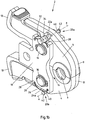
- FIG. 1 shows an embodiment of a pressing tool 2 according to the invention for connecting a pipe (not shown) and a fitting (not shown) in the closed position, with holding devices 20a in a first switching position A, in two perspective views.
- the pressing tool 2 has two pivoting elements 4 for pressing the pipe and the fitting.
- the pressing tool 2 has a receiving area 6 formed between the pivoting elements 4 for receiving the pipe and the fitting.
- the pivoting elements 4 each have a pressing section 8 and an actuating section 10.
- the operating portions 10 serve in practical use to initiate the pressing forces via an engine (not shown).
- the inner contours 12 of the pressing sections 8 form the receiving area 6.
- the receiving area 6 is moved from an open position during pressing (FIG. Fig. 2 ) in a closed position ( Fig.1 ), wherein the receiving area 6 in the closed position of the pivot elements 4 is narrower than in the open position of the pivot elements 4.
- pivoting elements 4 Between the pivoting elements 4 is an internal and a biasing spring comprehensive clamping mechanism 14 (not shown) for biasing the pressing tool 2 in the direction of the closed position.
- the pivot elements 4 are rotatably mounted on the pivot axes 16.
- the pivoting elements 4 are for pressing the tube and the fitting about the pivot axes 16 against each other.
- the pivot axes 16 are mounted in the support elements 18.
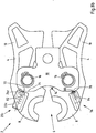
- the pressing tool 2 has two holding devices 20a for holding the pivoting elements 4 in the open position (FIG. Fig. 3 ) against the force generated by the biasing spring, wherein the holding devices 20a are switchable.
- the holding devices 20a and the clamping mechanism 14 form a switchable, bistable clamping mechanism.
- the respective holding device 20a has a latching element 22a and at least one latching recess 24a.
- the latching element 22a is a substantially cylindrical pin 22a
- the latching recess 24a is a recess 24a formed on a leaf spring 26.
- the leaf spring 26 is held in a form-fitting manner with its receptacle 30 of the support element 18 that is complementarily shaped at least in sections, with its end sections 28 bent over at the end substantially in a circular manner.
- the respective pin 22a of one of the holding devices 20a bears against a guide rail 32, which secures the pin 22a in the axial direction along the axis a of the pin 22a against undesired displacement.
- the guide rail 32 is a leaf spring 32 which is fixed to the support member 18 opposite the leaf spring 26.
- the bolt 22a has at its the guide rail 32 associated portion 34 has two spaced apart, circumferentially encircling grooves 36a, 36b, which cooperate with a guide rail 38 of the guide rail 32.
- the guideway 38 is curved in the direction of the bolt 22a.
- the grooves 36a, 36b each have a in Substantially to the curvature of the guideway 38 complementarily shaped groove cross section.
- the guideway 38 and the grooves 26a, 26b engage positively in one another.
- the bolt 22a is secured by the guide track 38 and the grooves 36a, 36b against displacement in the axial direction. When pivoting the pivot elements 4 relative to the support element 18, the bolt 22a is therefore guided relative to the support elements 18 along the guide track 38.
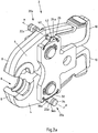
- FIG. 2 shows the pressing tool 2 from FIG. 1 in the open position, with the holding devices 20a in the first switching position A.
- FIG. 3 excerpt enlargements shows the pressing tool 2 FIG. 1 in the open position, with the holding devices 20a in a second switching position B, in two perspective views.
- the bolts 22a of the holding devices 20a are displaceable in the axial direction between the first switching position A and the second switching position B, wherein the bolts 22a in the first switching position A have a distance from the leaf spring 26 and rest in the second switching position B circumferentially on the leaf springs 26 ,
- the holding devices 20a do not oppose the clamping mechanism 14 and the clamping mechanism 14 is released. If the user releases the actuating sections 10 in the open position of the swivel elements 4, the swivel elements 4 are moved back into the closed position due to the spring force of the clamping mechanism 14 ( Fig. 1 ).
- the respective pin 22a is additionally projecting through a in the first switching position A across the width of the leaf spring 26 Guide section 40 out, which has a on the leaf spring 26 laterally adjacent, circular circumferential web 42.
- the holding devices 20a allow the user to set the pivoting elements 4 resiliently braced in the open position.
- the bolts 22a are moved in the open position along their respective axis a in the axial direction from the switching position A to the switching position B, which in FIG. 3 is shown.
- the axes a of the bolts 22a and the pivot axes 16 are substantially parallel to each other.
- the bolts 22a are guided on the respective pivoting element 4 in the holes 44 so as to move in a sliding manner.
- the guideway 38 in the switching position A encompassing groove 36a slides with the opposite direction of movement rising Nutinnen constitutional on the guideway 38 and pushes the guide rail 32 in the direction of the support member 18.
- the bolt 22a is moved in the direction of the switching position B until the guide rail 32 engages with the guide track 38 in the respective other groove 36b.
- the bolt 22a is seated with a partial length of the portion 34 in a formed on the pivot member 4 guide trough 46, against which the bolt 22a is supported laterally during pivoting of the pivot elements 4.
- the diameter of the leaf spring 26 in the switch position B ( Fig. 3 ) contacting portion 48 of the bolt 22a substantially corresponds to the diameter of the bore 44.
- the bolt 22a is tapered in the direction of the guide portion 40, so that between the bolt portion 48 and the guide portion 40 a circular circumferential chamfer 50th is provided.
- the bolt with the chamfer 50 threads into the recess 24a in order to ensure the correct positioning of the bolt 22a.
- FIG. 3 shows the pressing tool 2 with held in the open position the pivot elements 4, wherein the bolts 22a are in the switching position B.
- the bolts 22a abut with their leaf springs 26 associated portion 48 to the leaf springs 26 respectively.
- the pivot elements 4 are supported on the support elements 18 via the bolts 22a and the leaf springs 26.
- the leaf springs 26 are formed so stiff that they counteract a caused by the force of the clamping mechanism 14 slipping of the bolt 22 a along the leaf springs 26.
- the force introduced by the clamping mechanism 14 into the pivot elements 4, or the resulting moment about the pivot axes 16, is insufficient to displace the leaf springs 26 by means of the bolts 22a in the direction of the pivot axes 16 and thus the pivot elements 4 to move from the open position to the closed position.
- the pivot elements 4 are thus stably held in the open position.
- the labile intermediate position is the pivotal position of the pivot elements 4, in which the tensioning mechanism 14 and the holding device 20 in the pivoting elements introduced forces and moments about the pivot axes 14 cancel each other.
- the respective leaf spring 26 must be displaced by a force introduced from the outside with the bolt 22a in the direction of the support member 18 to the labile intermediate position of the pivot elements 4 in the direction of desired position of the pivot elements 4 to overcome.
- the bolt 22 a is guided during the movement of the pivot elements 4 from the open to the closed position along the guide track 38 of the guide rail 32.
- the bolt 22a therefore remains during the change of the pivot elements 4 from the open to the closed position, or vice versa, in its engaged position ( Fig. 4 ).
- the interaction between the guide rail 32 and the grooves 36a, 36b holds the bolt 22a therefore also for the subsequent pressing operations in the respectively set switching position A or B.
- the bistable behavior of the pressing tool 2 is maintained until the user the bolt 22a again actively moved from the switching position B in the switching position A.
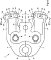
- FIGS. 5 and 6a show a further embodiment of a pressing tool 2 according to the invention in the closed position, with holding devices 20b in a first switching position A in a perspective view and a side view, wherein in the following with reference to the first embodiment, like reference numerals are assigned to like elements.
- the pressing tool 2 has two pivoting elements 4 for pressing a pipe (not shown) and a fitting (not shown), with a receiving area 6 formed between the pivoting elements 4 for receiving the pipe and the fitting.
- the pivot elements 4 are rotatably mounted about the pivot axes 16.
- the pivot axes 16 are supported by the support elements 18.
- the pivot elements 4 are for pressing the tube and the fitting about the pivot axes 18 against each other pivotally.
- One between the Swivel elements 4 and the support members 18 arranged clamping mechanism 14 is used to bias the pressing tool 2 in the direction of the closed position.
- the pressing tool 2 has two holding devices 20 b for holding the pivoting elements 4 in the open position against the biasing force generated by the clamping mechanism 14.
- the holding device 20b are switchable, wherein the holding device 20b and the clamping mechanism 14 form a switchable, bistable clamping mechanism.
- the holding devices 20b each have a latching element 22b and a latching recess 24b, wherein the latching recess 24b is designed as a latching groove 24b.
- the latching element 22b is a sliding element 22b guided slidingly on the one pivoting element 4.
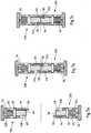
- FIG. 7 respectively sectional views of related to FIG. 6 shown switching positions shown.
- Figure 7a shows a sectional view of the holding devices along the line VII a - VII a FIG. 6a
- FIG. 7b shows a sectional view of the holding devices along the line VII b - VII b FIG. 6b
- FIG. 7c shows a sectional view of the holding devices along the line VII c - VII c FIG. 6c ,
- FIG. 6b shows the pressing tool 2 from FIG. 6a in the open position, with the holding devices 20b in the first switching position A.
- the receiving area 6 is in the open position of the pivot elements 4 according to FIG. 2b further than in the closed position of the pivot elements 4 FIG. 2a ,
- the pivot elements 4 are compressed in the area of the operating portions 10 by the user, without operating the holding devices 20b.
- the user grasps and actuates the actuating sections 10 at their respective sections 54 which are located upstream of the holding devices 20b in the direction of the receiving area 6.
- the sliding elements 22b remain in this case relative to the pivoting elements 4 in the in FIG FIG. 6a illustrated starting position.
- the sliding elements 22b engage in the in FIG. 6b shown open position of the pivot elements 4 not in the locking grooves 24b of the pivot elements 4 a.
- the sliding elements 22b are, as in the sectional views according to the FIGS. 7a and 7b shown biased by a helical compression spring 56 held in the first switching position A.
- FIG. 6c shows the pressing tool FIG. 6a in the open position, with the holding devices 20b in the second switching position B.
- the holding devices 20b counteract the clamping mechanism 14.
- the sliding elements 22b engage with their locking projections 58 in the locking grooves 24b.
- the respective sliding element 22b is between the first switching position A and the second shift position B slidably and on the associated pivot member 4 on two sides with a mandrel 60 in a groove 62 out.
- the engaged in the switching position B holding devices 20b hold the pivot elements 4 of the pressing tool 2 in the open position.
- the user actuates the actuating portions 10, starting from the in FIG. 6a shown position, in the region of the holding devices 20b.
- the user therefore compresses the operating sections 10 via the two sliding elements 22b.
- the sliding elements 22b are simultaneously displaced against the helical compression springs 56 in the direction of each provided on the opposite pivot elements 4 locking grooves 24b.
- the holding devices 20b may be made from the in FIG. 6b shown switching position A are transferred to the switching position B by the sliding elements 22b are shifted from each other, so that the locking projections 58 engage in the locking grooves 24b.
- the pressing tool 2 is in the in FIG. 6c illustrated switching position B of the holding devices 20b resiliently clamped in the open position of the pivot elements 4.
- the voltage applied to the pivot elements 4, the latching projections 58 supporting bending spring portions 64 of the sliding elements 22b counteract a sliding of the inclined surfaces 66 of the locking projections 42 at the edges 68 of the locking grooves 24b.
- the pivot members 4 are therefore stably held in the open position.
- the pivot elements 4 in the in FIG. 6a shown closed position in which the operating portions 10 by means of an engine (not shown) are spread.
- the engine is coupled to the coupling portions 70 of the support members 18 in a known manner.
- the actuating portions 10 are pressed apart, wherein the inclined surfaces 66 slide off at the edges 68 and thus the holding forces of the bending spring portions 64 are overcome.
- the pivoting elements 4 pivot back into the closed position due to the biasing force of the clamping mechanism 14.
- the sliding elements 22b are in turn, due to the helical compression springs 56, in the in FIG. 6a shown disengaged starting position moves back, in which they are held biased by the helical compression springs 56.
- FIG. 8 shows a third embodiment of a pressing tool 2 according to the invention, wherein in the following with reference to the preceding embodiments, like reference numerals are assigned to the same elements.
- FIG. 8a shows the pressing tool 2 in the closed position in a side view.
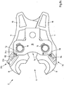
- the pressing tool 2 has a holding device 20c, which is formed by a pressure piece 22c and a trough 24c.
- the pressure piece 22 c has a detent ball 72 which is resiliently biased against a guide surface 74 formed on the support member 18.
- the pressure piece 22 c is fixed to the pivoting element 4 and the trough 24 c is provided on the support member 18 carrying the pivot axes 16.
- the guide surface 74 goes over without a jump in the trough 24c.
- the pressure piece 22 c has an external thread and is screwed into the pivoting element 4.
- a second pressure piece 76 is provided which counteracts pivoting of the pivot elements 4 from the closed to the open position in a pivoting range, wherein in particular the open position is part of this pivoting range.
- the pressure piece 76 has a detent ball 78, which is formed with a latching recess 80 co.
- the recess formed as a recess 80 80 is designed flat compared to the trough 24c.
- the detent ball 72 is resiliently biased biased to the guide surface 74 at.
- the pressure piece 22c is therefore located in the in FIG. 8a shown position in a tensioned state.
- the detent ball 78 of the second pressure piece 76 has a spacing from the support element 18 and the detent recess 80 formed thereon.
- the pressure piece 76 is in a relaxed state.
- the pivot elements 4 are biased by the tensioning mechanism 14 held in the closed position.
- the pivoting elements 4 are pressed against each other in the region of the actuating sections 10 in order to pivot the pivoting elements 4 counter to the clamping force of the clamping mechanism 14 around the respectively associated pivot axis 16.
- FIG. 8b shows the pivot elements 4 in an open position.
- pivot position of the pivot elements 4 is the pressure piece 22c in the first switching position A.
- the detent ball 72 is, as well as in the closed position of the pivot elements 4 in accordance FIG. 8a , At the side facing away from the pivot axis 16 guide surface 74 of the support member 18 at.
- the pressure piece 22c does not substantially counteract a pivoting back of the pivot elements 4 into the closed position by the tensioning mechanism 14, since the smooth shape of the guide surface 74, which does not surround the detent ball 72, causes the detent ball 72 to slide or slide along the latching ball 72 Guide surface 74 favors.
- the receiving area 6 is in the in FIG. 8b shown pivot position of the pivot elements 4 already open so far that the provided for pressing with the illustrated pressing tool 2 pipe sections and fittings (not shown) can be inserted into the receiving area 6.
- the pivot elements 4 on the in FIG. 8b shown pivot position are pivoted out, as in FIG. 8c shown.
- the pressure piece 22c takes the second switching position B, wherein the detent ball 72 is seated in the trough 24c.
- the detent ball 72 is engaged in the trough 24c, so that the pressure piece 22c is in the relaxed state.
- the detent ball may also continue to be held in the trough braced by the spring provided in the pressure piece.
- a defined pressure point is formed by the pressure piece 76, which indicates to the user when pivoting the pivot elements 4, in which pivoting range the transition of the first pressure piece 22c and the holding device 20c from the first sound position A takes place in the second switching position B.
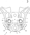
- FIG. 9 shows a fourth embodiment of a pressing tool 2 according to the invention in the closed position in a side view.
- This in FIG. 9 illustrated embodiment differs from the in FIG. 8 illustrated embodiment only in that the in FIG. 8 existing second pressure piece 76 has been replaced by a second holding device 20c according to the invention.
- provided on the support member 18 and the pivot member 4 marks 86 to the user, in which pivot position, the transition of the holding devices 20c from the first switching position A takes place in the second switching position B. If the markings 86 lie directly above one another, the pivoting elements 4 of the pressing tool 2 are in one of the FIG. 8b comparable pivotal position, wherein the holding devices 20c are in the first switching position A.
- the pressing tool it is also possible to provide only a single holding device in order to fix the pivoting elements in an open position.
- a the movement of the pivot elements coupling gear can be provided, so that pivoting or fixing of a pivot member causes pivoting or fixing the respective other pivot member.
Landscapes
- Engineering & Computer Science (AREA)
- Mechanical Engineering (AREA)
- Clamps And Clips (AREA)
- Details Of Spanners, Wrenches, And Screw Drivers And Accessories (AREA)
Claims (16)
- Outil de compression servant à l'assemblage d'un tube et d'un raccord, en particulier pour former un assemblage indétachable, ledit outil de compression- comprenant deux éléments pivotants (4) servant à la compression du tube et du raccord,- comprenant une zone de logement (6) formée entre les éléments pivotants (4), zone servant au logement du tube et du raccord,- comprenant au moins un axe de pivotement (16) servant au montage en rotation des éléments pivotants (4) et- comprenant un mécanisme de serrage (14) servant à la précontrainte de l'outil de compression (2),où les éléments pivotants (4) servant à la compression du tube et du raccord peuvent pivoter l'un contre l'autre autour de l'axe de pivotement (16) au moins au nombre de un,
où la zone de logement (6) est, dans une première position fermée, plus étroite que dans une deuxième position ouverte des éléments pivotants (4),
où les éléments pivotants (4) sont précontraints en direction de la position fermée, par le mécanisme de serrage (14), et
où il est prévu au moins un dispositif de retenue (20a, 20b, 20c) qui sert au maintien, dans la position ouverte, des éléments pivotants (4), et qui s'oppose à la force de précontrainte produite par le mécanisme de serrage (14),
caractérisé- en ce que le dispositif de retenue (20a, 20b, 20c) est actionnable et- en ce que le dispositif de retenue (20a, 20b, 20c) et le mécanisme de serrage (14) forment un mécanisme de serrage bistable actionnable. - Outil de compression selon la revendication 1,
caractérisé- en ce que le dispositif de retenue (20a, 20b, 20c) présente, dans la position ouverte des éléments pivotants (4), une première position de commande (A) dans laquelle le mécanisme de serrage (14) est libéré, et- en ce que le dispositif de retenue (20a, 20b, 20c) présente, dans la position ouverte des éléments pivotants (4), une seconde position de commande (B) dans laquelle le dispositif de retenue (20a, 20b, 20c) agit de façon antagoniste par rapport au mécanisme de serrage (14). - Outil de compression selon la revendication 2,
caractérisé
en ce que le dispositif de retenue (20a, 20b, 20c) est, dans la seconde position de commande (B), serré de manière élastique faisant ressort. - Outil de compression selon l'une des revendications 2 ou 3,
caractérisé
en ce que le dispositif de retenue (20a, 20b, 20c) présente au moins un élément d'encliquetage (22a, 22b, 22c) et au moins une cavité d'encliquetage (24a, 24b, 24c), où l'élément d'encliquetage (22a, 22b, 22c), dans la seconde position de commande (B), agit de façon conjointe avec la cavité d'encliquetage (24a, 24b, 24c). - Outil de compression selon la revendication 4,
caractérisé
en ce que l'élément d'encliquetage (22a, 22b, 22c) et la cavité d'encliquetage (24a, 24b, 24c) du dispositif de retenue (20a, 20b, 20c) sont prévus sur deux composants différents (4, 18), où ces composants (4, 18) peuvent pivoter l'un par rapport à l'autre autour de l'axe de pivotement (16), et où au moins l'un des composants (4, 18) est l'un des éléments pivotants (4). - Outil de compression selon l'une des revendications 4 ou 5,
caractérisé
en ce que l'élément d'encliquetage (22a, 22b) est un boulon (22a) pratiquement cylindrique, et la cavité d'encliquetage (24a, 24b) est un creux (24a) formé sur un ressort à lames (26). - Outil de compression selon la revendication 6,
caractérisé
en ce que le boulon (22a) peut être déplacé dans la direction axiale, entre la première position de commande (A) et la seconde position de commande (B), où le boulon (22a) présente, dans la première position de commande (A), une distance par rapport au ressort à lames (26) et, dans la seconde position de commande (B), est en appui sur le ressort à lames (26), par son côté circonférentiel. - Outil de compression selon l'une des revendications 6 ou 7,
caractérisé
en ce que le boulon (22a) est en appui sur un rail de guidage (32) qui maintient le boulon (22a) dans la position de commande axiale respective (A, B). - Outil de compression selon la revendication 8,
caractérisé
en ce que le rail de guidage (32) est un ressort à lames (32). - Outil de compression selon l'une des revendications 8 ou 9,
caractérisé
en ce que le boulon (22a) présente, sur la partie (34) associée au rail de guidage (32), deux rainures (36a, 36b) circulaires sur le côté circonférentiel et disposées en étant à distance l'une de l'autre, rainures qui, dans la position de commande respective (A, B), agissent de façon conjointe avec une glissière de guidage (38) du rail de guidage (32). - Outil de compression selon l'une des revendications 4 ou 5,
caractérisé
en ce que l'élément d'encliquetage (22a, 22b) présente un élément coulissant (22b) guidé en étant mobile, de façon coulissante, sur l'un des éléments pivotants (4), où l'élément coulissant (22b) peut être déplacé en coulissant entre la première position de commande (A) et la seconde position de commande (B), et la cavité d'encliquetage (24a, 24b) est formée sur l'autre élément pivotant (4). - Outil de compression selon la revendication 11,
caractérisé
en ce que l'élément coulissant (22b) est maintenu de façon précontrainte dans la première position de commande (A). - Outil de compression selon l'une des revendications 11 ou 12,
caractérisé
en ce qu'il est prévu, sur les éléments pivotants (4), deux éléments coulissants (22b) et deux cavités d'encliquetage (24b). - Outil de compression selon l'une des revendications 4 ou 5,
caractérisé
en ce que l'élément d'encliquetage (22a, 22b, 22c) est une pièce de pression (22c), où la pièce de pression (22c) présente, dans la première position de commande (A), en particulier une bille d'encliquetage (72) précontrainte de manière élastique faisant ressort, bille d'encliquetage qui, dans la seconde position de commande (B), se trouve dans une cavité d'encliquetage (24a, 24b, 24c) formée comme une auge (24c). - Outil de compression selon la revendication 14,
caractérisé
en ce que la pièce de pression (22c) est fixée sur l'un des éléments pivotants (4), et la cavité d'encliquetage (22a, 22b, 22c) est prévue sur un élément de support (18) supportant l'axe de pivotement (16). - Outil de compression selon la revendication 15,
caractérisé
en ce qu'il est prévu une deuxième pièce de pression (76) qui, dans une zone de pivotement, s'oppose à un basculement des éléments pivotants (4), les empêchant de passer de la position fermée à la position ouverte, où en particulier la position ouverte est une partie de la zone de pivotement.
Applications Claiming Priority (1)
| Application Number | Priority Date | Filing Date | Title |
|---|---|---|---|
| DE102014112869.9A DE102014112869B3 (de) | 2014-09-08 | 2014-09-08 | Presswerkzeug mit zuschaltbarem bistabilen Spannmechanismus |
Publications (2)
| Publication Number | Publication Date |
|---|---|
| EP2995426A1 EP2995426A1 (fr) | 2016-03-16 |
| EP2995426B1 true EP2995426B1 (fr) | 2017-01-11 |
Family
ID=54064218
Family Applications (1)
| Application Number | Title | Priority Date | Filing Date |
|---|---|---|---|
| EP15183860.4A Active EP2995426B1 (fr) | 2014-09-08 | 2015-09-04 | Outil de presse dote d'un mecanisme de serrage commutable bistable |
Country Status (3)
| Country | Link |
|---|---|
| US (1) | US10399138B2 (fr) |
| EP (1) | EP2995426B1 (fr) |
| DE (1) | DE102014112869B3 (fr) |
Families Citing this family (3)
| Publication number | Priority date | Publication date | Assignee | Title |
|---|---|---|---|---|
| WO2022111753A1 (fr) * | 2020-11-24 | 2022-06-02 | Rothenberger Ag | Outil de pression radiale |
| DE102022115433A1 (de) | 2022-06-21 | 2023-12-21 | Novopress Gmbh Pressen Und Presswerkzeuge & Co. Kommanditgesellschaft | Pressring, Pressschlinge und Presswerkzeug mit Verstellelement |
| USD1025732S1 (en) * | 2023-08-03 | 2024-05-07 | Qing Dai | Hydraulic tool |
Family Cites Families (14)
| Publication number | Priority date | Publication date | Assignee | Title |
|---|---|---|---|---|
| US2979032A (en) * | 1958-05-12 | 1961-04-11 | Bahco Ab | Hydraulically operable hand tools |
| US4426869A (en) * | 1982-06-01 | 1984-01-24 | Litton Industrial Products, Inc. | Radial infeed thread roll attachment |
| US6044686A (en) * | 1990-04-12 | 2000-04-04 | Dischler; Helmut | Compression tool for compression molding die |
| DE29703053U1 (de) * | 1997-02-21 | 1997-04-10 | Novopress GmbH Pressen und Presswerkzeuge & Co KG, 41460 Neuss | Preßgerät |
| EP1092487A3 (fr) * | 1999-10-15 | 2004-08-25 | Gustav Klauke GmbH | Dispositif de pressage avec machoires de compression |
| US6386532B1 (en) * | 2001-03-12 | 2002-05-14 | The Boeing Company | Clamp squeeze apparatus and method |
| US6860017B1 (en) * | 2001-03-21 | 2005-03-01 | Jerry Mennicken | Single-spring or double-spring biased nipper |
| US6644636B1 (en) * | 2001-10-26 | 2003-11-11 | M. Terry Ryan | Clamp adapter |
| DE202006013693U1 (de) * | 2006-09-07 | 2008-01-17 | Gustav Klauke Gmbh | Pressbackenpaar für hydraulische oder elektrische Verpressgeräte |
| WO2006031548A2 (fr) * | 2004-09-09 | 2006-03-23 | Emerson Electric Co. | Ensemble machoire a duree de vie controlee |
| DE102007061164B4 (de) * | 2007-12-17 | 2010-03-04 | Viega Gmbh & Co. Kg | Presswerkzeug mit bistabilem Spannungsmechanismus |
| US8573576B2 (en) * | 2009-06-26 | 2013-11-05 | Intuitive Research And Technology Corporation | Clamp for single-handed operation |
| US8347471B2 (en) * | 2011-01-09 | 2013-01-08 | Wang yuan yu | Ratchet pliers for snap ring |
| WO2017192547A1 (fr) * | 2016-05-02 | 2017-11-09 | Hubbell Incorporated | Outil de sertissage hydraulique en ligne |
-
2014
- 2014-09-08 DE DE102014112869.9A patent/DE102014112869B3/de not_active Expired - Fee Related
-
2015
- 2015-09-03 US US14/844,634 patent/US10399138B2/en not_active Expired - Fee Related
- 2015-09-04 EP EP15183860.4A patent/EP2995426B1/fr active Active
Non-Patent Citations (1)
| Title |
|---|
| None * |
Also Published As
| Publication number | Publication date |
|---|---|
| US10399138B2 (en) | 2019-09-03 |
| DE102014112869B3 (de) | 2016-01-07 |
| EP2995426A1 (fr) | 2016-03-16 |
| US20160067761A1 (en) | 2016-03-10 |
Similar Documents
| Publication | Publication Date | Title |
|---|---|---|
| DE69507991T2 (de) | Verriegelbare zange mit achsialer spannbewegung | |
| DE3410047A1 (de) | Permutationsschloss zum sichern von skiern, fahrraedern oder dergleichen | |
| DE29616632U1 (de) | Chirurgisches Anlegegerät für U-förmige Clipse | |
| DE102015101829A1 (de) | Spannklaue zur Anbringung an einer Gleitschiene eines Operationstisches | |
| EP1648660B1 (fr) | Mecanisme pas a pas pour outil de serrage a barre | |
| DE19614832C1 (de) | Säge für chirurgische Zwecke | |
| EP3010665B1 (fr) | Outil de pliage | |
| DE29907864U1 (de) | Wasserpumpenzange mit Einhandbedienung | |
| EP2007553A1 (fr) | Outil à main à ouverture automatique | |
| DE102014212441A1 (de) | Gasauslassventil für ein hydraulisches Ausrücksystem einer Kupplung | |
| DE102007061164B4 (de) | Presswerkzeug mit bistabilem Spannungsmechanismus | |
| DE102014102662A1 (de) | Steckverbindung für Fluid-Leitungen und Halteteil für eine derartige Steckverbindung | |
| DE102014112869B3 (de) | Presswerkzeug mit zuschaltbarem bistabilen Spannmechanismus | |
| DE69317128T2 (de) | Motorangetriebener greifer mit zwei greiferbacken | |
| DE19943750B4 (de) | Übertragungselement zwischen einem Türgriff und einem Türschloß eines Kraftfahrzeugs | |
| DE1282111C2 (de) | Voreinstellbare drucktasteneinrichtung | |
| AT514903B1 (de) | Scharnier | |
| DE69605240T2 (de) | In zwei Richtungen wirkende Arretiervorrichtung in einer einstellbaren Steueranlage mit Bowdenzug oder Betätigungsstange | |
| EP2796245A1 (fr) | Outil de presse | |
| DE10335353B4 (de) | Schrittgetriebe mit großer Schrittweite | |
| DE102018210281B4 (de) | Handbetätigungseinrichtung und damit ausgestattetes Ventil | |
| DE102006001268B3 (de) | Bidirektionale federgestützte Zwischenspeicherung in elektronischen Schliess-Systemen | |
| DE102015220983B3 (de) | Fenster- oder Türgriffgarnitur | |
| EP4382717A1 (fr) | Cadre de tension pour une moustiquaire | |
| DE102024127263A1 (de) | Elektrochirurgische Zange mit verschiebbarer Schneideinheit und Rückstellmechanismus |
Legal Events
| Date | Code | Title | Description |
|---|---|---|---|
| PUAI | Public reference made under article 153(3) epc to a published international application that has entered the european phase |
Free format text: ORIGINAL CODE: 0009012 |
|
| AK | Designated contracting states |
Kind code of ref document: A1 Designated state(s): AL AT BE BG CH CY CZ DE DK EE ES FI FR GB GR HR HU IE IS IT LI LT LU LV MC MK MT NL NO PL PT RO RS SE SI SK SM TR |
|
| AX | Request for extension of the european patent |
Extension state: BA ME |
|
| 17P | Request for examination filed |
Effective date: 20160310 |
|
| RBV | Designated contracting states (corrected) |
Designated state(s): AL AT BE BG CH CY CZ DE DK EE ES FI FR GB GR HR HU IE IS IT LI LT LU LV MC MK MT NL NO PL PT RO RS SE SI SK SM TR |
|
| GRAP | Despatch of communication of intention to grant a patent |
Free format text: ORIGINAL CODE: EPIDOSNIGR1 |
|
| RIC1 | Information provided on ipc code assigned before grant |
Ipc: B21D 39/04 20060101ALI20160804BHEP Ipc: B25B 27/10 20060101AFI20160804BHEP |
|
| INTG | Intention to grant announced |
Effective date: 20160901 |
|
| GRAS | Grant fee paid |
Free format text: ORIGINAL CODE: EPIDOSNIGR3 |
|
| GRAA | (expected) grant |
Free format text: ORIGINAL CODE: 0009210 |
|
| AK | Designated contracting states |
Kind code of ref document: B1 Designated state(s): AL AT BE BG CH CY CZ DE DK EE ES FI FR GB GR HR HU IE IS IT LI LT LU LV MC MK MT NL NO PL PT RO RS SE SI SK SM TR |
|
| REG | Reference to a national code |
Ref country code: GB Ref legal event code: FG4D Free format text: NOT ENGLISH |
|
| REG | Reference to a national code |
Ref country code: CH Ref legal event code: EP |
|
| REG | Reference to a national code |
Ref country code: AT Ref legal event code: REF Ref document number: 860824 Country of ref document: AT Kind code of ref document: T Effective date: 20170115 |
|
| REG | Reference to a national code |
Ref country code: CH Ref legal event code: NV Representative=s name: SCHMAUDER AND PARTNER AG PATENT- UND MARKENANW, CH |
|
| REG | Reference to a national code |
Ref country code: NL Ref legal event code: FP |
|
| REG | Reference to a national code |
Ref country code: IE Ref legal event code: FG4D Free format text: LANGUAGE OF EP DOCUMENT: GERMAN |
|
| REG | Reference to a national code |
Ref country code: DE Ref legal event code: R096 Ref document number: 502015000495 Country of ref document: DE |
|
| RAP2 | Party data changed (patent owner data changed or rights of a patent transferred) |
Owner name: VIEGA TECHNOLOGY GMBH & CO. KG |
|
| REG | Reference to a national code |
Ref country code: DE Ref legal event code: R082 Ref document number: 502015000495 Country of ref document: DE Representative=s name: COHAUSZ & FLORACK PATENT- UND RECHTSANWAELTE P, DE Ref country code: DE Ref legal event code: R081 Ref document number: 502015000495 Country of ref document: DE Owner name: VIEGA TECHNOLOGY GMBH & CO. KG, DE Free format text: FORMER OWNER: VIEGA GMBH & CO. KG, 57439 ATTENDORN, DE |
|
| REG | Reference to a national code |
Ref country code: LT Ref legal event code: MG4D |
|
| REG | Reference to a national code |
Ref country code: NL Ref legal event code: PD Owner name: VIEGA TECHNOLOGY GMBH & CO. KG; DE Free format text: DETAILS ASSIGNMENT: CHANGE OF OWNER(S), ASSIGNMENT; FORMER OWNER NAME: VIEGA GMBH & CO. KG Effective date: 20170412 |
|
| PG25 | Lapsed in a contracting state [announced via postgrant information from national office to epo] |
Ref country code: FI Free format text: LAPSE BECAUSE OF FAILURE TO SUBMIT A TRANSLATION OF THE DESCRIPTION OR TO PAY THE FEE WITHIN THE PRESCRIBED TIME-LIMIT Effective date: 20170111 Ref country code: GR Free format text: LAPSE BECAUSE OF FAILURE TO SUBMIT A TRANSLATION OF THE DESCRIPTION OR TO PAY THE FEE WITHIN THE PRESCRIBED TIME-LIMIT Effective date: 20170412 Ref country code: HR Free format text: LAPSE BECAUSE OF FAILURE TO SUBMIT A TRANSLATION OF THE DESCRIPTION OR TO PAY THE FEE WITHIN THE PRESCRIBED TIME-LIMIT Effective date: 20170111 Ref country code: IS Free format text: LAPSE BECAUSE OF FAILURE TO SUBMIT A TRANSLATION OF THE DESCRIPTION OR TO PAY THE FEE WITHIN THE PRESCRIBED TIME-LIMIT Effective date: 20170511 Ref country code: LT Free format text: LAPSE BECAUSE OF FAILURE TO SUBMIT A TRANSLATION OF THE DESCRIPTION OR TO PAY THE FEE WITHIN THE PRESCRIBED TIME-LIMIT Effective date: 20170111 Ref country code: NO Free format text: LAPSE BECAUSE OF FAILURE TO SUBMIT A TRANSLATION OF THE DESCRIPTION OR TO PAY THE FEE WITHIN THE PRESCRIBED TIME-LIMIT Effective date: 20170411 |
|
| REG | Reference to a national code |
Ref country code: GB Ref legal event code: 732E Free format text: REGISTERED BETWEEN 20170706 AND 20170715 |
|
| PG25 | Lapsed in a contracting state [announced via postgrant information from national office to epo] |
Ref country code: SE Free format text: LAPSE BECAUSE OF FAILURE TO SUBMIT A TRANSLATION OF THE DESCRIPTION OR TO PAY THE FEE WITHIN THE PRESCRIBED TIME-LIMIT Effective date: 20170111 Ref country code: RS Free format text: LAPSE BECAUSE OF FAILURE TO SUBMIT A TRANSLATION OF THE DESCRIPTION OR TO PAY THE FEE WITHIN THE PRESCRIBED TIME-LIMIT Effective date: 20170111 Ref country code: LV Free format text: LAPSE BECAUSE OF FAILURE TO SUBMIT A TRANSLATION OF THE DESCRIPTION OR TO PAY THE FEE WITHIN THE PRESCRIBED TIME-LIMIT Effective date: 20170111 Ref country code: PL Free format text: LAPSE BECAUSE OF FAILURE TO SUBMIT A TRANSLATION OF THE DESCRIPTION OR TO PAY THE FEE WITHIN THE PRESCRIBED TIME-LIMIT Effective date: 20170111 Ref country code: PT Free format text: LAPSE BECAUSE OF FAILURE TO SUBMIT A TRANSLATION OF THE DESCRIPTION OR TO PAY THE FEE WITHIN THE PRESCRIBED TIME-LIMIT Effective date: 20170511 Ref country code: BG Free format text: LAPSE BECAUSE OF FAILURE TO SUBMIT A TRANSLATION OF THE DESCRIPTION OR TO PAY THE FEE WITHIN THE PRESCRIBED TIME-LIMIT Effective date: 20170411 Ref country code: ES Free format text: LAPSE BECAUSE OF FAILURE TO SUBMIT A TRANSLATION OF THE DESCRIPTION OR TO PAY THE FEE WITHIN THE PRESCRIBED TIME-LIMIT Effective date: 20170111 |
|
| REG | Reference to a national code |
Ref country code: DE Ref legal event code: R097 Ref document number: 502015000495 Country of ref document: DE |
|
| PG25 | Lapsed in a contracting state [announced via postgrant information from national office to epo] |
Ref country code: SK Free format text: LAPSE BECAUSE OF FAILURE TO SUBMIT A TRANSLATION OF THE DESCRIPTION OR TO PAY THE FEE WITHIN THE PRESCRIBED TIME-LIMIT Effective date: 20170111 Ref country code: RO Free format text: LAPSE BECAUSE OF FAILURE TO SUBMIT A TRANSLATION OF THE DESCRIPTION OR TO PAY THE FEE WITHIN THE PRESCRIBED TIME-LIMIT Effective date: 20170111 Ref country code: EE Free format text: LAPSE BECAUSE OF FAILURE TO SUBMIT A TRANSLATION OF THE DESCRIPTION OR TO PAY THE FEE WITHIN THE PRESCRIBED TIME-LIMIT Effective date: 20170111 Ref country code: CZ Free format text: LAPSE BECAUSE OF FAILURE TO SUBMIT A TRANSLATION OF THE DESCRIPTION OR TO PAY THE FEE WITHIN THE PRESCRIBED TIME-LIMIT Effective date: 20170111 |
|
| PLBE | No opposition filed within time limit |
Free format text: ORIGINAL CODE: 0009261 |
|
| STAA | Information on the status of an ep patent application or granted ep patent |
Free format text: STATUS: NO OPPOSITION FILED WITHIN TIME LIMIT |
|
| PG25 | Lapsed in a contracting state [announced via postgrant information from national office to epo] |
Ref country code: DK Free format text: LAPSE BECAUSE OF FAILURE TO SUBMIT A TRANSLATION OF THE DESCRIPTION OR TO PAY THE FEE WITHIN THE PRESCRIBED TIME-LIMIT Effective date: 20170111 Ref country code: SM Free format text: LAPSE BECAUSE OF FAILURE TO SUBMIT A TRANSLATION OF THE DESCRIPTION OR TO PAY THE FEE WITHIN THE PRESCRIBED TIME-LIMIT Effective date: 20170111 |
|
| 26N | No opposition filed |
Effective date: 20171012 |
|
| PG25 | Lapsed in a contracting state [announced via postgrant information from national office to epo] |
Ref country code: SI Free format text: LAPSE BECAUSE OF FAILURE TO SUBMIT A TRANSLATION OF THE DESCRIPTION OR TO PAY THE FEE WITHIN THE PRESCRIBED TIME-LIMIT Effective date: 20170111 |
|
| PG25 | Lapsed in a contracting state [announced via postgrant information from national office to epo] |
Ref country code: MC Free format text: LAPSE BECAUSE OF FAILURE TO SUBMIT A TRANSLATION OF THE DESCRIPTION OR TO PAY THE FEE WITHIN THE PRESCRIBED TIME-LIMIT Effective date: 20170111 |
|
| REG | Reference to a national code |
Ref country code: IE Ref legal event code: MM4A |
|
| REG | Reference to a national code |
Ref country code: BE Ref legal event code: MM Effective date: 20170930 |
|
| PG25 | Lapsed in a contracting state [announced via postgrant information from national office to epo] |
Ref country code: LU Free format text: LAPSE BECAUSE OF NON-PAYMENT OF DUE FEES Effective date: 20170904 |
|
| REG | Reference to a national code |
Ref country code: FR Ref legal event code: ST Effective date: 20180531 |
|
| PG25 | Lapsed in a contracting state [announced via postgrant information from national office to epo] |
Ref country code: IE Free format text: LAPSE BECAUSE OF NON-PAYMENT OF DUE FEES Effective date: 20170904 |
|
| PG25 | Lapsed in a contracting state [announced via postgrant information from national office to epo] |
Ref country code: BE Free format text: LAPSE BECAUSE OF NON-PAYMENT OF DUE FEES Effective date: 20170930 Ref country code: FR Free format text: LAPSE BECAUSE OF NON-PAYMENT OF DUE FEES Effective date: 20171002 |
|
| PG25 | Lapsed in a contracting state [announced via postgrant information from national office to epo] |
Ref country code: MT Free format text: LAPSE BECAUSE OF FAILURE TO SUBMIT A TRANSLATION OF THE DESCRIPTION OR TO PAY THE FEE WITHIN THE PRESCRIBED TIME-LIMIT Effective date: 20170111 |
|
| PG25 | Lapsed in a contracting state [announced via postgrant information from national office to epo] |
Ref country code: HU Free format text: LAPSE BECAUSE OF FAILURE TO SUBMIT A TRANSLATION OF THE DESCRIPTION OR TO PAY THE FEE WITHIN THE PRESCRIBED TIME-LIMIT; INVALID AB INITIO Effective date: 20150904 |
|
| PG25 | Lapsed in a contracting state [announced via postgrant information from national office to epo] |
Ref country code: CY Free format text: LAPSE BECAUSE OF FAILURE TO SUBMIT A TRANSLATION OF THE DESCRIPTION OR TO PAY THE FEE WITHIN THE PRESCRIBED TIME-LIMIT Effective date: 20170111 |
|
| PG25 | Lapsed in a contracting state [announced via postgrant information from national office to epo] |
Ref country code: MK Free format text: LAPSE BECAUSE OF FAILURE TO SUBMIT A TRANSLATION OF THE DESCRIPTION OR TO PAY THE FEE WITHIN THE PRESCRIBED TIME-LIMIT Effective date: 20170111 |
|
| PG25 | Lapsed in a contracting state [announced via postgrant information from national office to epo] |
Ref country code: TR Free format text: LAPSE BECAUSE OF FAILURE TO SUBMIT A TRANSLATION OF THE DESCRIPTION OR TO PAY THE FEE WITHIN THE PRESCRIBED TIME-LIMIT Effective date: 20170111 |
|
| PG25 | Lapsed in a contracting state [announced via postgrant information from national office to epo] |
Ref country code: AL Free format text: LAPSE BECAUSE OF FAILURE TO SUBMIT A TRANSLATION OF THE DESCRIPTION OR TO PAY THE FEE WITHIN THE PRESCRIBED TIME-LIMIT Effective date: 20170111 |
|
| REG | Reference to a national code |
Ref country code: AT Ref legal event code: MM01 Ref document number: 860824 Country of ref document: AT Kind code of ref document: T Effective date: 20200904 |
|
| PG25 | Lapsed in a contracting state [announced via postgrant information from national office to epo] |
Ref country code: AT Free format text: LAPSE BECAUSE OF NON-PAYMENT OF DUE FEES Effective date: 20200904 |
|
| REG | Reference to a national code |
Ref country code: CH Ref legal event code: U11 Free format text: ST27 STATUS EVENT CODE: U-0-0-U10-U11 (AS PROVIDED BY THE NATIONAL OFFICE) Effective date: 20251001 |
|
| PGFP | Annual fee paid to national office [announced via postgrant information from national office to epo] |
Ref country code: DE Payment date: 20250922 Year of fee payment: 11 |
|
| PGFP | Annual fee paid to national office [announced via postgrant information from national office to epo] |
Ref country code: NL Payment date: 20250922 Year of fee payment: 11 Ref country code: IT Payment date: 20250923 Year of fee payment: 11 |
|
| PGFP | Annual fee paid to national office [announced via postgrant information from national office to epo] |
Ref country code: GB Payment date: 20250923 Year of fee payment: 11 |
|
| PGFP | Annual fee paid to national office [announced via postgrant information from national office to epo] |
Ref country code: CH Payment date: 20251001 Year of fee payment: 11 |