EP2995447B1 - Workshop hydraulic press - Google Patents
Workshop hydraulic press Download PDFInfo
- Publication number
- EP2995447B1 EP2995447B1 EP14382342.5A EP14382342A EP2995447B1 EP 2995447 B1 EP2995447 B1 EP 2995447B1 EP 14382342 A EP14382342 A EP 14382342A EP 2995447 B1 EP2995447 B1 EP 2995447B1
- Authority
- EP
- European Patent Office
- Prior art keywords
- shaped part
- press
- block
- workbench
- side edge
- Prior art date
- Legal status (The legal status is an assumption and is not a legal conclusion. Google has not performed a legal analysis and makes no representation as to the accuracy of the status listed.)
- Active
Links
Images


Classifications
-
- B—PERFORMING OPERATIONS; TRANSPORTING
- B30—PRESSES
- B30B—PRESSES IN GENERAL
- B30B1/00—Presses, using a press ram, characterised by the features of the drive therefor, pressure being transmitted directly, or through simple thrust or tension members only, to the press ram or platen
- B30B1/32—Presses, using a press ram, characterised by the features of the drive therefor, pressure being transmitted directly, or through simple thrust or tension members only, to the press ram or platen by plungers under fluid pressure
- B30B1/326—Presses, using a press ram, characterised by the features of the drive therefor, pressure being transmitted directly, or through simple thrust or tension members only, to the press ram or platen by plungers under fluid pressure operated by hand or foot, e.g. using hydraulic jacks
-
- B—PERFORMING OPERATIONS; TRANSPORTING
- B30—PRESSES
- B30B—PRESSES IN GENERAL
- B30B15/00—Details of, or accessories for, presses; Auxiliary measures in connection with pressing
- B30B15/02—Dies; Inserts therefor; Mounting thereof; Moulds
- B30B15/026—Mounting of dies, platens or press rams
-
- B—PERFORMING OPERATIONS; TRANSPORTING
- B30—PRESSES
- B30B—PRESSES IN GENERAL
- B30B15/00—Details of, or accessories for, presses; Auxiliary measures in connection with pressing
- B30B15/08—Accessory tools, e.g. knives; Mountings therefor
Definitions
- the present invention relates to a workshop hydraulic press for manipulating and working parts, having application in the machine tool industry and, more specifically, in the field of mechanic's shops, which allows making the tasks of working and manipulating said parts easier for the operators.
- a hydraulic press comprises a closed hydraulic circuit in which a hydraulic fluid moves through the different components of the hydraulic circuit.
- Energy generating equipment usually a hydraulic pump, applies pressure on the hydraulic fluid.
- the energy contained in the hydraulic fluid is transmitted to a hydraulic cylinder or actuator having an inner piston.
- the piston applies the force necessary for the operation to be performed on the part to be manipulated, this press force or load being of great magnitude.
- the high working forces mean that handling of the hydraulic press for the tasks of manipulating parts has various safety problems. Handling of the hydraulic press also involves risks for the operator since the parts involved have a certain mass and are subjected to said high forces.
- the workshop hydraulic press Before handling the workshop hydraulic press, it is essential to immobilize to the greatest extent possible the part to be manipulated, which is arranged on a workbench comprising the press itself, so that said part is fixed when performing the operations.
- the workbench of the hydraulic press Before placing and fixing the part, the workbench of the hydraulic press must be positioned at a suitable working height.
- blocks having a planar face and in which a part comprising a V-shaped notch or depression is fixed on the opposite face must be placed on the workbench, such that when the part to be worked on has a planar configuration, the mentioned part is placed on the planar face of the blocks, whereas if the part is a tube, it is placed on the V-shaped notch of the opposite face.
- the blocks have two working positions and the operator must change between these two working positions by means of turning the blocks depending on the geometry of each part.
- the present invention relates to a workshop hydraulic press which allows making the work of the operators using the hydraulic press easier so that said work can be performed in a safer and more comfortable manner.
- the objective of the invention is to make manipulating the parts in the workbench easier and to prevent oils, fats and other residual materials from falling through the workbench to the floor or to the lower portions of the press
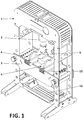
- the workshop hydraulic press proposed by the invention is defined by claim 1 and comprises a structural chassis, comprising a front panel and a back panel.
- the press also comprises a hydraulic cylinder which can act on a part to be manipulated for machining, acting by compression, for example, and a workbench on which there is located at least one, preferably two, block(s) on which the part or the set of parts to be manipulated can be supported.
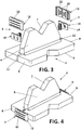
- Each block in turn comprises a first planar face and a second face opposite the first face from which a support part having a preferably a V-shaped depression or notch emerge, preferably according to a plane transverse to the second face, to receive the part to be manipulated.
- each block comprises two side edges, where each side edge has, coupled thereto, a stop so that it is immobilized on the workbench.
- each stop comprises a T-shaped part which can be fitted into a transverse groove made on each side edge of said block.
- Each stop in turn comprises a hollow I-shaped part comprising a longitudinal groove in which the flanges of the T-shaped part can be inserted.
- the I-shaped part has a height greater than the side edge of the block such that the I-shaped part always protrudes from the side edge of the block in any case. This feature allows the I-shaped part to be located externally with respect to the workbench, immobilizing the block in any case regardless of the working position required at any particular time.
- each T-shaped part comprising, on the inner face of the flanges, at least one boss is contemplated, which boss, when the T-shaped part is inserted in the I-shaped part, has a play in a transverse groove correspondingly located on the inner face of said I-shaped part, defining two limit positions for the T-shaped part when it is inserted in the I-shaped part.
- the I-shaped part has a height greater than the height of the side edges of the blocks when the blocks are turned over to change the orientation of the part to be manipulated, for example, to change the face of the part to be machined, the I-shaped part falls by gravity and the T-shaped part is inserted in the longitudinal groove because the boss acts as a stop at the end of the transverse groove.
- the invention contemplates that the workshop hydraulic press described above additionally comprises a detachable residue collection tray which can be located inside the workbench or in a lower area of the workbench.
- the press comprises two inclined side bars fixed internally between the panels of the workbench or of the chassis, such that the collection tray is placed by means of its inclined sides being supported with said inclined side bars.
- the tray acts as a collector element for collecting the residual material originating from manipulating the parts.
- the tray When the tray is located in a lower position with respect to the workbench, it can also be used to place parts and tools that can be used in the work being performed at that time or in future work. In this lower position of the press, the tray is also supported with its upper borders both on the front panel and on the back panel of the chassis of the press.
- the workshop hydraulic press proposed by the invention comprises a chassis (1), a hydraulic cylinder (2) which can act on a part to be manipulated and a workbench (3) on which there are located two blocks (4) for supporting a part or a set of parts to be manipulated, which is not depicted.
- each block (4) comprises a first planar face (5) and a second face from which a support part (6) having a V-shaped depression (7) emerge, according to a plane transverse to the second face, to receive the part to be manipulated.
- each block (4) comprises two side edges (8), where each side edge (8) has, coupled thereto, a stop (9) so that it is immobilized on the workbench (3).
- Each stop (9) in turn comprises a plastic T-shaped part (10) fitting into a transverse groove (11) made on each side edge (8) of said block (4).
- Each stop (9) in turn comprises a hollow I-shaped part (12) comprising a longitudinal groove (13) in which the flanges of the T-shaped part (10) can be inserted.
- the I-shaped part (12) has a height greater than the side edge (8) of the block (4) such that the I-shaped part (12) always protrudes from the side edge (8) of the block (4) in any case when the T-shaped part (10) is inserted in the transverse groove (11), as seen in the two positions depicted in Figures 1 and 2 .
- each T-shaped part (10) comprises, on the inner face of the flanges, two bosses (14) which, when the T-shaped part (10) is inserted in the I-shaped part (12), have a play in two transverse grooves (15) correspondingly located on the inner face of said I-shaped part (12), defining two limit positions for the T-shaped part (10) when it is inserted in the I-shaped part (12).
- the workshop hydraulic press comprises a detachable tool and/or residue collection tray (16) which can be located inside the workbench (3) or in a lower area of the press.
- the press comprises two inclined side bars (17) arranged inside the workbench (3) and fixed to the front and back panels of the mentioned workbench (3).
- other two inclined bars (17') attached to the front and back panels of the chassis (1) of the workshop press have been envisaged for placing the tray in a lower position with respect to the workbench (3).
- the tray is coupled by gravity between the bars (17) and/or (17'), the inclined sides of the tray being supported on the mentioned bars. If the collection tray (16) is placed in the lower portion of the press, the upper borders of said collection tray (16) are supported on the front panel and on the back panel of the chassis (1) of the press in addition to on the bars (17').
- a collection tray (16) is thus incorporated to the press for collecting residual material originating from the cylinder or from the actual parts that are being worked on, however, said tray can also be used for leaving tools or spare parts that may be used when working on a part in the press.
- the collection tray (16) When the collection tray (16) is placed in any of the two positions, it is secured at least by the contact existing between the inclined side bars (17) and the inclined sides (18) of the collection tray (16) itself which has an inclination equal to the inclination of the mentioned inclined side bars (17).
Landscapes
- Engineering & Computer Science (AREA)
- Mechanical Engineering (AREA)
- Physics & Mathematics (AREA)
- Fluid Mechanics (AREA)
- Bending Of Plates, Rods, And Pipes (AREA)
Priority Applications (2)
| Application Number | Priority Date | Filing Date | Title |
|---|---|---|---|
| EP14382342.5A EP2995447B1 (en) | 2014-09-11 | 2014-09-11 | Workshop hydraulic press |
| ES14382342T ES2700512T3 (es) | 2014-09-11 | 2014-09-11 | Prensa hidráulica de taller |
Applications Claiming Priority (1)
| Application Number | Priority Date | Filing Date | Title |
|---|---|---|---|
| EP14382342.5A EP2995447B1 (en) | 2014-09-11 | 2014-09-11 | Workshop hydraulic press |
Publications (2)
| Publication Number | Publication Date |
|---|---|
| EP2995447A1 EP2995447A1 (en) | 2016-03-16 |
| EP2995447B1 true EP2995447B1 (en) | 2018-09-05 |
Family
ID=51868159
Family Applications (1)
| Application Number | Title | Priority Date | Filing Date |
|---|---|---|---|
| EP14382342.5A Active EP2995447B1 (en) | 2014-09-11 | 2014-09-11 | Workshop hydraulic press |
Country Status (2)
| Country | Link |
|---|---|
| EP (1) | EP2995447B1 (es) |
| ES (1) | ES2700512T3 (es) |
Family Cites Families (5)
| Publication number | Priority date | Publication date | Assignee | Title |
|---|---|---|---|---|
| US3307830A (en) * | 1965-10-23 | 1967-03-07 | John L Van Allen | Combination hydraulic press and puller |
| CN201186500Y (zh) * | 2008-04-09 | 2009-01-28 | 傅勇刚 | 一种双面使用的压机垫块 |
| CN201333809Y (zh) * | 2008-12-01 | 2009-10-28 | 傅勇刚 | 气动手动两用压机 |
| CN101830075B (zh) * | 2010-05-21 | 2012-05-02 | 常熟通润汽车零部件股份有限公司 | 千斤顶液压压力机 |
| ES1082704Y (es) * | 2013-05-20 | 2013-09-16 | Melchor Gabilondo Sa | Prensa hidráulica con zona de recogida de piezas |
-
2014
- 2014-09-11 ES ES14382342T patent/ES2700512T3/es active Active
- 2014-09-11 EP EP14382342.5A patent/EP2995447B1/en active Active
Also Published As
| Publication number | Publication date |
|---|---|
| ES2700512T3 (es) | 2019-02-18 |
| EP2995447A1 (en) | 2016-03-16 |
Similar Documents
| Publication | Publication Date | Title |
|---|---|---|
| EP2995447B1 (en) | Workshop hydraulic press | |
| EP1441867B1 (en) | Multipurpose horizontal press having a fixed workpiece-holder for a tubular workpiece to be drawn or tapered | |
| CN104308419A (zh) | 一种u形内折弯钣金件夹紧工装 | |
| JP5916925B1 (ja) | パイプの切断装置及び切断方法 | |
| US4641516A (en) | Bending tool | |
| CN106077962A (zh) | 一种镭射打标治具 | |
| EP2585263A2 (en) | Method for manufacturing frame of c- clamp, frame of c-clamp and c-clamp | |
| KR20150088578A (ko) | 공작 기계용 슬라이드 커버 | |
| CN203956764U (zh) | 一种可升降台虎钳支架 | |
| JP5742738B2 (ja) | 多段プレス装置、及びその制御方法 | |
| KR102195543B1 (ko) | 소형 자동차 부품의 성형을 위한 프레스 금형 및 그에 의한 소형 자동차 부품의 제조 방법 | |
| KR19990034199U (ko) | 롤 베어링 분해용 지그 | |
| US4989310A (en) | King pin pressing tool | |
| CN208713932U (zh) | 一种油压钣金组 | |
| EP2977193B1 (en) | Shop hydraulic press | |
| CN220942674U (zh) | 一种零件冲压折弯结构 | |
| EP3181257A3 (de) | Ziehwerkzeug zur umformung von werkstücken | |
| CN2831551Y (zh) | 多功能电力安装组合设备 | |
| CN215965756U (zh) | 一种汽车模具冲压板机构 | |
| CN214722663U (zh) | 一种具有废料回收功能的金属结构件加工装置 | |
| CN215240674U (zh) | 一种可减少冲击的铸铁平台 | |
| US20210299988A1 (en) | Portable Power-Driven Press | |
| US9862013B2 (en) | Apparatus for deformation of solid sections | |
| CN209110276U (zh) | 一种耐磨损的钢结构加工用剪板机 | |
| CN209793201U (zh) | 一种变速箱攻丝夹具 |
Legal Events
| Date | Code | Title | Description |
|---|---|---|---|
| PUAI | Public reference made under article 153(3) epc to a published international application that has entered the european phase |
Free format text: ORIGINAL CODE: 0009012 |
|
| AK | Designated contracting states |
Kind code of ref document: A1 Designated state(s): AL AT BE BG CH CY CZ DE DK EE ES FI FR GB GR HR HU IE IS IT LI LT LU LV MC MK MT NL NO PL PT RO RS SE SI SK SM TR |
|
| AX | Request for extension of the european patent |
Extension state: BA ME |
|
| 17P | Request for examination filed |
Effective date: 20160916 |
|
| RBV | Designated contracting states (corrected) |
Designated state(s): AL AT BE BG CH CY CZ DE DK EE ES FI FR GB GR HR HU IE IS IT LI LT LU LV MC MK MT NL NO PL PT RO RS SE SI SK SM TR |
|
| GRAP | Despatch of communication of intention to grant a patent |
Free format text: ORIGINAL CODE: EPIDOSNIGR1 |
|
| STAA | Information on the status of an ep patent application or granted ep patent |
Free format text: STATUS: GRANT OF PATENT IS INTENDED |
|
| GRAS | Grant fee paid |
Free format text: ORIGINAL CODE: EPIDOSNIGR3 |
|
| GRAA | (expected) grant |
Free format text: ORIGINAL CODE: 0009210 |
|
| STAA | Information on the status of an ep patent application or granted ep patent |
Free format text: STATUS: THE PATENT HAS BEEN GRANTED |
|
| INTG | Intention to grant announced |
Effective date: 20180711 |
|
| AK | Designated contracting states |
Kind code of ref document: B1 Designated state(s): AL AT BE BG CH CY CZ DE DK EE ES FI FR GB GR HR HU IE IS IT LI LT LU LV MC MK MT NL NO PL PT RO RS SE SI SK SM TR |
|
| REG | Reference to a national code |
Ref country code: GB Ref legal event code: FG4D |
|
| REG | Reference to a national code |
Ref country code: CH Ref legal event code: EP |
|
| REG | Reference to a national code |
Ref country code: AT Ref legal event code: REF Ref document number: 1037307 Country of ref document: AT Kind code of ref document: T Effective date: 20180915 |
|
| REG | Reference to a national code |
Ref country code: IE Ref legal event code: FG4D |
|
| REG | Reference to a national code |
Ref country code: DE Ref legal event code: R096 Ref document number: 602014031682 Country of ref document: DE |
|
| REG | Reference to a national code |
Ref country code: NL Ref legal event code: MP Effective date: 20180905 |
|
| REG | Reference to a national code |
Ref country code: LT Ref legal event code: MG4D |
|
| PG25 | Lapsed in a contracting state [announced via postgrant information from national office to epo] |
Ref country code: FI Free format text: LAPSE BECAUSE OF FAILURE TO SUBMIT A TRANSLATION OF THE DESCRIPTION OR TO PAY THE FEE WITHIN THE PRESCRIBED TIME-LIMIT Effective date: 20180905 Ref country code: SE Free format text: LAPSE BECAUSE OF FAILURE TO SUBMIT A TRANSLATION OF THE DESCRIPTION OR TO PAY THE FEE WITHIN THE PRESCRIBED TIME-LIMIT Effective date: 20180905 Ref country code: RS Free format text: LAPSE BECAUSE OF FAILURE TO SUBMIT A TRANSLATION OF THE DESCRIPTION OR TO PAY THE FEE WITHIN THE PRESCRIBED TIME-LIMIT Effective date: 20180905 Ref country code: BG Free format text: LAPSE BECAUSE OF FAILURE TO SUBMIT A TRANSLATION OF THE DESCRIPTION OR TO PAY THE FEE WITHIN THE PRESCRIBED TIME-LIMIT Effective date: 20181205 Ref country code: LT Free format text: LAPSE BECAUSE OF FAILURE TO SUBMIT A TRANSLATION OF THE DESCRIPTION OR TO PAY THE FEE WITHIN THE PRESCRIBED TIME-LIMIT Effective date: 20180905 Ref country code: GR Free format text: LAPSE BECAUSE OF FAILURE TO SUBMIT A TRANSLATION OF THE DESCRIPTION OR TO PAY THE FEE WITHIN THE PRESCRIBED TIME-LIMIT Effective date: 20181206 Ref country code: NO Free format text: LAPSE BECAUSE OF FAILURE TO SUBMIT A TRANSLATION OF THE DESCRIPTION OR TO PAY THE FEE WITHIN THE PRESCRIBED TIME-LIMIT Effective date: 20181205 |
|
| REG | Reference to a national code |
Ref country code: AT Ref legal event code: MK05 Ref document number: 1037307 Country of ref document: AT Kind code of ref document: T Effective date: 20180905 |
|
| REG | Reference to a national code |
Ref country code: ES Ref legal event code: FG2A Ref document number: 2700512 Country of ref document: ES Kind code of ref document: T3 Effective date: 20190218 |
|
| PG25 | Lapsed in a contracting state [announced via postgrant information from national office to epo] |
Ref country code: LV Free format text: LAPSE BECAUSE OF FAILURE TO SUBMIT A TRANSLATION OF THE DESCRIPTION OR TO PAY THE FEE WITHIN THE PRESCRIBED TIME-LIMIT Effective date: 20180905 Ref country code: HR Free format text: LAPSE BECAUSE OF FAILURE TO SUBMIT A TRANSLATION OF THE DESCRIPTION OR TO PAY THE FEE WITHIN THE PRESCRIBED TIME-LIMIT Effective date: 20180905 Ref country code: AL Free format text: LAPSE BECAUSE OF FAILURE TO SUBMIT A TRANSLATION OF THE DESCRIPTION OR TO PAY THE FEE WITHIN THE PRESCRIBED TIME-LIMIT Effective date: 20180905 |
|
| PG25 | Lapsed in a contracting state [announced via postgrant information from national office to epo] |
Ref country code: IS Free format text: LAPSE BECAUSE OF FAILURE TO SUBMIT A TRANSLATION OF THE DESCRIPTION OR TO PAY THE FEE WITHIN THE PRESCRIBED TIME-LIMIT Effective date: 20190105 Ref country code: NL Free format text: LAPSE BECAUSE OF FAILURE TO SUBMIT A TRANSLATION OF THE DESCRIPTION OR TO PAY THE FEE WITHIN THE PRESCRIBED TIME-LIMIT Effective date: 20180905 Ref country code: EE Free format text: LAPSE BECAUSE OF FAILURE TO SUBMIT A TRANSLATION OF THE DESCRIPTION OR TO PAY THE FEE WITHIN THE PRESCRIBED TIME-LIMIT Effective date: 20180905 Ref country code: AT Free format text: LAPSE BECAUSE OF FAILURE TO SUBMIT A TRANSLATION OF THE DESCRIPTION OR TO PAY THE FEE WITHIN THE PRESCRIBED TIME-LIMIT Effective date: 20180905 Ref country code: RO Free format text: LAPSE BECAUSE OF FAILURE TO SUBMIT A TRANSLATION OF THE DESCRIPTION OR TO PAY THE FEE WITHIN THE PRESCRIBED TIME-LIMIT Effective date: 20180905 Ref country code: IT Free format text: LAPSE BECAUSE OF FAILURE TO SUBMIT A TRANSLATION OF THE DESCRIPTION OR TO PAY THE FEE WITHIN THE PRESCRIBED TIME-LIMIT Effective date: 20180905 Ref country code: CZ Free format text: LAPSE BECAUSE OF FAILURE TO SUBMIT A TRANSLATION OF THE DESCRIPTION OR TO PAY THE FEE WITHIN THE PRESCRIBED TIME-LIMIT Effective date: 20180905 Ref country code: PL Free format text: LAPSE BECAUSE OF FAILURE TO SUBMIT A TRANSLATION OF THE DESCRIPTION OR TO PAY THE FEE WITHIN THE PRESCRIBED TIME-LIMIT Effective date: 20180905 |
|
| REG | Reference to a national code |
Ref country code: CH Ref legal event code: PL |
|
| PG25 | Lapsed in a contracting state [announced via postgrant information from national office to epo] |
Ref country code: SM Free format text: LAPSE BECAUSE OF FAILURE TO SUBMIT A TRANSLATION OF THE DESCRIPTION OR TO PAY THE FEE WITHIN THE PRESCRIBED TIME-LIMIT Effective date: 20180905 Ref country code: SK Free format text: LAPSE BECAUSE OF FAILURE TO SUBMIT A TRANSLATION OF THE DESCRIPTION OR TO PAY THE FEE WITHIN THE PRESCRIBED TIME-LIMIT Effective date: 20180905 Ref country code: PT Free format text: LAPSE BECAUSE OF FAILURE TO SUBMIT A TRANSLATION OF THE DESCRIPTION OR TO PAY THE FEE WITHIN THE PRESCRIBED TIME-LIMIT Effective date: 20190105 |
|
| REG | Reference to a national code |
Ref country code: DE Ref legal event code: R097 Ref document number: 602014031682 Country of ref document: DE |
|
| REG | Reference to a national code |
Ref country code: BE Ref legal event code: MM Effective date: 20180930 |
|
| REG | Reference to a national code |
Ref country code: IE Ref legal event code: MM4A |
|
| PG25 | Lapsed in a contracting state [announced via postgrant information from national office to epo] |
Ref country code: LU Free format text: LAPSE BECAUSE OF NON-PAYMENT OF DUE FEES Effective date: 20180911 |
|
| PLBE | No opposition filed within time limit |
Free format text: ORIGINAL CODE: 0009261 |
|
| STAA | Information on the status of an ep patent application or granted ep patent |
Free format text: STATUS: NO OPPOSITION FILED WITHIN TIME LIMIT |
|
| PG25 | Lapsed in a contracting state [announced via postgrant information from national office to epo] |
Ref country code: DK Free format text: LAPSE BECAUSE OF FAILURE TO SUBMIT A TRANSLATION OF THE DESCRIPTION OR TO PAY THE FEE WITHIN THE PRESCRIBED TIME-LIMIT Effective date: 20180905 Ref country code: MC Free format text: LAPSE BECAUSE OF FAILURE TO SUBMIT A TRANSLATION OF THE DESCRIPTION OR TO PAY THE FEE WITHIN THE PRESCRIBED TIME-LIMIT Effective date: 20180905 Ref country code: IE Free format text: LAPSE BECAUSE OF NON-PAYMENT OF DUE FEES Effective date: 20180911 |
|
| 26N | No opposition filed |
Effective date: 20190606 |
|
| PG25 | Lapsed in a contracting state [announced via postgrant information from national office to epo] |
Ref country code: SI Free format text: LAPSE BECAUSE OF FAILURE TO SUBMIT A TRANSLATION OF THE DESCRIPTION OR TO PAY THE FEE WITHIN THE PRESCRIBED TIME-LIMIT Effective date: 20180905 Ref country code: LI Free format text: LAPSE BECAUSE OF NON-PAYMENT OF DUE FEES Effective date: 20180930 Ref country code: BE Free format text: LAPSE BECAUSE OF NON-PAYMENT OF DUE FEES Effective date: 20180930 Ref country code: CH Free format text: LAPSE BECAUSE OF NON-PAYMENT OF DUE FEES Effective date: 20180930 |
|
| PG25 | Lapsed in a contracting state [announced via postgrant information from national office to epo] |
Ref country code: MT Free format text: LAPSE BECAUSE OF NON-PAYMENT OF DUE FEES Effective date: 20180911 |
|
| PG25 | Lapsed in a contracting state [announced via postgrant information from national office to epo] |
Ref country code: TR Free format text: LAPSE BECAUSE OF FAILURE TO SUBMIT A TRANSLATION OF THE DESCRIPTION OR TO PAY THE FEE WITHIN THE PRESCRIBED TIME-LIMIT Effective date: 20180905 |
|
| PG25 | Lapsed in a contracting state [announced via postgrant information from national office to epo] |
Ref country code: MK Free format text: LAPSE BECAUSE OF NON-PAYMENT OF DUE FEES Effective date: 20180905 Ref country code: CY Free format text: LAPSE BECAUSE OF FAILURE TO SUBMIT A TRANSLATION OF THE DESCRIPTION OR TO PAY THE FEE WITHIN THE PRESCRIBED TIME-LIMIT Effective date: 20180905 Ref country code: HU Free format text: LAPSE BECAUSE OF FAILURE TO SUBMIT A TRANSLATION OF THE DESCRIPTION OR TO PAY THE FEE WITHIN THE PRESCRIBED TIME-LIMIT; INVALID AB INITIO Effective date: 20140911 |
|
| REG | Reference to a national code |
Ref country code: GB Ref legal event code: 732E Free format text: REGISTERED BETWEEN 20231207 AND 20231213 |
|
| REG | Reference to a national code |
Ref country code: DE Ref legal event code: R081 Ref document number: 602014031682 Country of ref document: DE Owner name: NEW MEGA XXI, S.L., ES Free format text: FORMER OWNER: MELCHOR GABILONDO, S.A., BERRIZ, BIZKAIA, ES |
|
| REG | Reference to a national code |
Ref country code: ES Ref legal event code: PC2A Owner name: NEW MEGA XXI, S.L. Effective date: 20240626 |
|
| PGFP | Annual fee paid to national office [announced via postgrant information from national office to epo] |
Ref country code: DE Payment date: 20250919 Year of fee payment: 12 |
|
| PGFP | Annual fee paid to national office [announced via postgrant information from national office to epo] |
Ref country code: GB Payment date: 20250902 Year of fee payment: 12 |
|
| PGFP | Annual fee paid to national office [announced via postgrant information from national office to epo] |
Ref country code: FR Payment date: 20250902 Year of fee payment: 12 |
|
| PGFP | Annual fee paid to national office [announced via postgrant information from national office to epo] |
Ref country code: ES Payment date: 20251003 Year of fee payment: 12 |