EP2995504A1 - Support de toit pour un vehicule automobile - Google Patents
Support de toit pour un vehicule automobile Download PDFInfo
- Publication number
- EP2995504A1 EP2995504A1 EP15183549.3A EP15183549A EP2995504A1 EP 2995504 A1 EP2995504 A1 EP 2995504A1 EP 15183549 A EP15183549 A EP 15183549A EP 2995504 A1 EP2995504 A1 EP 2995504A1
- Authority
- EP
- European Patent Office
- Prior art keywords
- profile
- rear carrier
- carrier
- axis
- functional
- Prior art date
- Legal status (The legal status is an assumption and is not a legal conclusion. Google has not performed a legal analysis and makes no representation as to the accuracy of the status listed.)
- Granted
Links
Images




Classifications
-
- B—PERFORMING OPERATIONS; TRANSPORTING
- B60—VEHICLES IN GENERAL
- B60R—VEHICLES, VEHICLE FITTINGS, OR VEHICLE PARTS, NOT OTHERWISE PROVIDED FOR
- B60R9/00—Supplementary fittings on vehicle exterior for carrying loads, e.g. luggage, sports gear or the like
- B60R9/06—Supplementary fittings on vehicle exterior for carrying loads, e.g. luggage, sports gear or the like at vehicle front or rear
Definitions
- the invention relates to a rear carrier for a motor vehicle with a holder for securing the rear carrier vehicle fixed, with a support frame on which the holder is arranged, and on which at least one functional platform is mounted, which can be folded relative to the support frame about a pivot axis into a compact storage position and is tilted about a tilt axis in a loading and unloading position.
- Such a rear carrier is from the DE 10 2008 006 814 A1 known.
- the known rear carrier is provided for mounting in a rear region of a passenger car and has a support frame which is mounted relative to the motor vehicle between an operating position and a loading and unloading about a pivot axis extending in the vehicle transverse direction pivot axis.
- On the support frame several functional platforms are provided, which serve to support and secure bicycles. These functional platforms are mounted to pivot in the vehicle longitudinal direction extending folding axes between a non-use position and a functional position.
- the object of the invention is to provide a rear carrier of the type mentioned, which has good functionality and at the same time simple structure.
- the folding axis and the tilting axis are defined by a one-piece carrier profile which is rotatably mounted relative to the support frame about the tilting axis, and on which the at least one functional platform is pivotally mounted.
- the carrier profile has at least one angled portion, wherein the profile section formed by the angling is preferably aligned coaxially to the folding axis and the other profile section is aligned coaxially with the tilting axis.
- the bend can be achieved in particular by crimping a corresponding metallic carrier profile, so that the carrier profile represents a cranked one-piece carrier profile.
- the cranked carrier profile has a double function in that on the one hand it carries the at least one functional platform in a pivotable manner and on the other hand is rotatably mounted about the tilting axis in order to tilt the at least one functional platform into the loading and unloading position.
- an angled Stirnend Scheme the carrier profile form the folding axis by a bearing pin or a coaxial bearing bore.
- the one-part design of the carrier profile also means a one-piece structural unit in which a plurality of parts and sections are detachably or non-detachably connected in one piece to the carrier profile.
- the solution according to the invention is suitable in a particularly advantageous manner for rear carriers, which are fastened on the rear side to ball heads of trailer hitches of passenger cars.
- the support frame of Rear carrier associated with a coupling device which cooperates with the ball head.
- a holder for securing the rear carrier at the rear of the passenger car and a plug fuse or a differently designed holding device may be provided for releasable connection to the rear of the passenger car.
- more than one functional platform is provided.
- a functional platform holding and recording media are provided on which leisure equipment such as bicycles or similar can be parked and secured in order to transport them together with the passenger car can.
- a corresponding functional platform can be constructed in one or more parts. For securing the corresponding leisure equipment such as bicycles or the like on at least one functional platform securing or holding elements are provided which support the corresponding leisure device on the functional platform in a defined position and secure.
- the carrier profile is designed in one piece.
- the one-piece design can be formed by a one-piece, correspondingly angled hollow or solid metal profile, or by a plurality of profile sections, which are rigidly joined together to handle the one-piece component carrier profile.
- the solution according to the invention provides a considerably lower-vibration rear carrier when driving, which enables safer transportation of large leisure devices such as bicycles.
- the rear carrier according to the invention has a particularly compact construction. In the rest position of the at least one functional platform, the rear carrier is narrowly folded, so that it does not require a large storage space for non-use.
- the rear carrier can also be mounted from a reduced compared to the prior art number of components, which simplifies the manufacture and assembly and reduces the cost of manufacturing and assembly of the rear carrier.
- the support frame itself may have a simplified structure. Because the carrier profile can serve as a rear-side cross member of the support frame and thus contributes directly to the stiffening of the support frame.
- the folding axes are oriented obliquely so that forces acting on the at least one functional platform of the rear carrier during a driving operation of a motor vehicle, can be particularly well received on the carrier profile.
- two mirror-symmetrically folding functional platforms are provided, which are mounted around a respective folding axis on the carrier profile, and the two folding axes and the tilt axis of the carrier profile are aligned in the vehicle side mounted state of the rear carrier in a vertical vehicle transverse plane.
- the two folding axes are aligned in each case by the same amount acute angle relative to the vehicle transverse direction extending tilt axis of the carrier profile mirror-symmetrically each outwardly increasing, to pivot the function platforms from a horizontal to a vertical position by simply turning the corresponding To allow folding axis.
- the functional platform in a first end position, ie in a functional position, in the assembled state of the rear carrier aligned approximately horizontally and in the second end position, namely the rest position, upright or inclined extends upward, so that the rear carrier has a total of more compact outer contours than in the functional position of the functional platforms.
- the vertical vehicle transverse plane in which the tilting axis and the folding axes of the carrier profile are aligned in the assembled state of the rear carrier on a corresponding motor vehicle, is a vertical transverse plane, which is aligned behind the rear area of the vehicle in the vehicle transverse direction.
- the carrier profile on a central portion and two on opposite sides of the central portion angularly projecting bearing journal, wherein the central portion is rotatably mounted about the tilt axis and the bearing journals each rotatably support a functional platform about the pivot axis.
- the bearing journals are cranked as a profile leg relative to the central portion aligned and the carrier profile is an integral hollow profile of a light metal alloy, in particular an aluminum alloy, which forms the central portion and the profile legs.
- the bearing pins are designed as relative to the central portion oppositely cranked profile legs.
- the journals are integrated into angularly aligned Stirnend Schemee the carrier profile.
- the central portion is cylindrical.
- the profile legs are cylindrical. This allows the profile legs themselves serve directly as a cylindrical bearing pin for a rotatable mounting of the respective functional platform. Again, the corresponding folding axis is identical to the central longitudinal axis of the respective cylindrical profile leg.
- the central portion and the two profile legs are either made by cold deformation of a corresponding metallic hollow profile, or they are made as separate hollow profile sections, which are then welded together in the desired orientation or connected in a similar manner cohesively.
- the carrier profile end stops are assigned to limit the Kippbewegige about the tilt axis. This ensures that the carrier profile, on which the functional platforms are arranged, is securely positioned both in the operating position and in the loading and unloading position.
- the carrier profile can be assigned additional detents for these end positions, which engage automatically spring-loaded automatically and are manually detachable.
- the support frame has at least one bearing receptacle for tiltable mounting of the carrier profile.
- the at least one bearing receptacle is formed by a bearing shell or a bearing sleeve, which protrudes from the rear side of the support frame and engages around the central portion of the carrier profile.
- the bearing receiver is preferably a separate bearing component, which is firmly connected to the support frame.
- the profile legs of the carrier profile and / or corresponding bearing parts of each functional platform end stops for limiting the pivoting movement of the functional platforms relative to the legs. This ensures that the functional platforms are assigned defined end positions in which they are blocked against further pivoting or rotational movement.
- the end stops are associated with additional mechanical locking means which secure the respective functional platform in the corresponding end position on the carrier profile, and which are manually detachable.
- Bearing parts are bearing journals, bearing mounts and similar parts that define a pivot bearing function for the functional platforms and / or the support profile.
- a passenger car P according to the Fig. 2 to 6 has a tailgate H in a rear area, which pivots about a pivot axis extending in the vehicle transverse direction from the illustrated, closed state to the rear and up to be transferred to the open position.
- a rear portion of the passenger car P is provided below a rear-side bumper with a ball head of a trailer hitch.
- a rear carrier 1 On a spherical head according to the representations on Fig. 2 to 6 attached a rear carrier 1, based on the Fig. 1 as well as on the basis of Fig. 2 to 7 is explained in more detail.
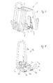
- the rear carrier 1 according to the Fig. 1 to 7 has a support frame 2, which is designed as a simple, bulky curved frame profile.
- the frame profile has two U-legs, which lie in a common plane and are aligned parallel to each other.
- the two USchenkel are integrally connected to each other over a curvature region, to which a holder 3 is rigidly fixed, which is provided for fixing the frame profile to the ball head of the towing hitch P of the passenger car.
- the holder 3 has, in a basically known manner, a clamping unit which, in the mounted state, encloses the ball-head positively and non-positively.
- the holder 3 is manually clamped by means of a movable operating handle in a corresponding clamping position or released from the clamping position to remove the rear carrier 1 of the ball head of the trailer hitch again.
- the bearing mounts 7 are formed by two mutually complementary bearing shells, which enclose a cylindrical shell of the central portion of the support section 4.
- the bearings of the bearing mounts 7 are integrally connected with mounting shells which surround the Stirnend Schemee the U-legs of the frame profile 2 and in particular are connected by riveting or by other fasteners firmly with this.
- the frame profile 2 like the carrier profile 4, has a cylindrical lateral surface.
- Both the frame profile 2 and the carrier profile 4 are made of a cylindrical hollow profile, which consists of a light metal alloy, in particular an aluminum alloy.
- the carrier profile 4 is rotatable relative to the frame profile 4 about the tilting axis K.
- the carrier profile 4 contributes via its connection to the frame profile 2 by means of the bearing receivers 7 for stiffening the serving as a support frame 2 frame profile by the carrier profile 4 connects the Stirnend Schemee the two U-legs of the frame profile with each other via the bearing receivers 7.
- the two U-legs of the frame profile are in the assembled state parallel to each other in the vehicle longitudinal direction.
- the carrier profile 4 is provided at its opposite ends, in each case laterally outside of the bearing receptacles 7, each with a support plate 5, which is designed as a rectangular, in particular as a square flat plate.
- the support plate 5 is obliquely aligned at an acute angle of in particular slightly more than 45 ° relative to the tilting axis K at the respective front end of the support section 4 and in particular fixedly connected by welding to the respective front end of the support section 4.
- Each support plate 5 is provided with a bearing pin, not shown, which is integrally secured by welding or screwing or in a similar manner to the support section 4 or the support plate 5 and projects from a surface of the respective support plate 5 at right angles obliquely upwards and outwards.
- Each bearing pin thus forms a respective relative to the carrier profile 4 rigid rotation axis S 1 , S 2 , which are also referred to as folding axes.
- the two axes of rotation S 1 , S 2 protrude coaxially to the respective bearing pin perpendicularly from the respective surface of the respective support plate 5 and are thereby inclined at an acute angle of approximately 45 ° relative to the tilt axis K in a vertical vehicle transverse plane obliquely upwards and outwards as can be seen from the dot-dash lines for the axes of rotation S 1 , S 2 and the tilting axis K.
- each functional platform 6, 8 of the rear carrier 1 is rotatably supported, wherein a corresponding Vermosebene respectively by the plane surface of the support plate or the respective defined by the bearing pin radial plane relative to the respective axis of rotation S 1 , S 2 corresponds.
- Each functional platform 6, 8 is formed by a support structure 6 and by a functional structure 8, wherein the functional structure 8 the support structure 6 is rigidly secured.
- the functional structure 8 has holding and supporting means for two bicycles F and in each case a tail lamp arrangement.
- at least one of the two functional structures 8 is provided with a license plate holder.
- the functional structure 8 is supported and fixed on a flat, plate-shaped surface of the respective support structure 6, so that the respective support structure 6 and the associated functional structure 8 as a permanently connected assembly unit in the form of the functional platform 6, 8 uniformly about the respective axis of rotation S 1 , S. 2 are rotatable.
- a handling bar 9 rigidly connected to the carrier profile 4 is a handling bar 9, which has a position according to FIG Fig. 1 vertically upwardly projecting, U-shaped bracket portion and two horizontally in the vehicle longitudinal direction to the rear projecting to the support section 4 mounting leg includes, which are in particular by welding or in a similar manner rigidly connected to the support section 4.
- end stops are provided in a manner not shown limiting the rotational movement of the support section 4 about the tilt axis K.
- the limitation by means of the end stops takes place in two end positions, namely a normal operating position of the carrier profile 4 (FIG. Fig. 1 ) and a backward rotated loading and unloading position ( Fig. 3 ).
- the carrier profile 4 is supported by the end stops against further rotation.
- the carrier profile 4 also not shown locking means assigned to lock the carrier profile 4 in this operating position.
- the locking means can be solved by an operator by means of a corresponding handling option.
- a corresponding locking preferably by mechanical locking means, preferably takes place as soon as the carrier profile 4 has reached the operating position.
- the handling bracket 9 pivots due to its rigid connection with the carrier profile 4 together with the carrier profile 4 and the function platforms 6, 8.
- the handling bracket 9 allows an operator to control a tilting movement to the rear or to the front and possibly decelerate.
- Each support structure 6 of the respective functional platform has a bearing sleeve which is rotatably slid onto the bearing journal of the respective support plate 5.
- the bearing sleeve is integrated in the support structure 6 and rigidly connected to the support structure 6.
- the bearing sleeve is matched with its inner diameter on the respective bearing journal, that results in a radially backlash-free rotational mobility of the bearing sleeve relative to the bearing journal.
- the rotatability of the support structure 6 is defined together with the functional structure 8 relative to the support plate 5 about the respective axis of rotation S 1 , S 2 .
- end stops are provided in a manner not shown having a VerFDbewegige restrict the support structure 6 relative to the support plate 5 to a twist angle of 180 °. Due to the acute-angled orientation of the oblique plane of rotation, a surface of the support structure 6 is accordingly from the horizontal operating position according to Fig. 1 in a folded position according to Fig. 7 twisted, in which the surface of the support structure 6 is inclined upward and slightly inclined to the center, so that the functional structures 8 are upright, but slightly inclined to the center.
- the angle between the respective axis of rotation S 1 , S 2 and the tilting axis K extending in the vehicle transverse direction is slightly greater than 45 ° in order, in accordance with a rotation of the respective functional platform 6, 8 from the horizontal Fig. 1 to achieve a slight inclination towards the center of the respective support structure 6, as shown in FIG Fig. 7 is recognizable.
- locking means are additionally provided to the support structure 6 relative to the support section 4, ie relative to the respective support plate 5 in the two end positions, ie the operating position according to the Fig. 1 and 2 and the folding position according to Fig. 7 , releasably lock. A release of the locking means is done manually by an operator.
- Fig. 7 It can be seen that in the folded position of the two functional platforms 6, 8 of the rear carrier 1 is compactly folded and thus takes up little space.
- the two axes of rotation S 1 , S 2 and the tilting axis K are in ready assembled state of the rear carrier 1 to a corresponding passenger car P in a common vertical vehicle transverse plane.
- a further embodiment of a rear carrier 1a is shown.
- the rear carrier 1a has the same functional principle with respect to its tilting into a loading and unloading position and with respect to the pivotable foldability of its functional platforms 6a, 8a, so that below only the differences of the structural embodiments of the rear carrier 1a relative to the rear carrier 1 is discussed.
- Functionally identical parts and sections are provided with the same reference numerals and with the addition of the letter a.
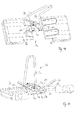
- the rear carrier 1a according to the 8 to 12 a carrier profile 4a, which is designed as a cylindrical hollow profile.
- the carrier profile 4a is rotatably mounted in the same manner in bearing receptacles 7a, as in the embodiment of the Fig. 1 to 7 the case is.
- the design of the support frame 2a and the connection of the handling bracket 9a with the carrier profile 4a are identical to those in the embodiment according to FIGS Fig. 1 to 7 , so that no further explanations are necessary to avoid repetition. The same applies to the design and mounting of the holder 3a on the U-shaped curvature region of the support frame 2a.
- the support section 4a starting from its central portion to both front ends in each case a bent profile leg 5a merges, wherein the central portion and the profile legs 5a connect in one piece.
- a cranked transition region between the profile legs 5a and the central portion of the carrier profile 4a can be made by cold deformation.
- the profile legs 5a are cylindrical and have the same diameter as the central portion of the support section 4a. In an embodiment of the invention, not shown, the two profile legs 5a are connected by welding to the central portion of the support section 4a.
- a central longitudinal axis of each profile leg 5a corresponds to the respective axis of rotation S 1 , S 2 , around which the functional platforms 8a, 6a are mounted so as to be limitedly rotatable.
- Both axes of rotation S 1 , S 2 are based on the tilt axis K analogous to the embodiment of the Fig. 1 to 7 directed at equal angles obliquely outwards and upwards, this angle is selected in terms of amount from a range between 40 ° and 60 ° relative to the tilting axis K.
- the two functional platforms 6a, 8a are formed by a cup-shaped, cylindrical support sleeve 6a and by a functional structure 8a, which is largely identical to the functional structure 8 according to FIGS Fig. 1 to 7 is executed.
- the cup-shaped support sleeve 6a is matched with respect to its inner diameter to the outer diameter of the respective profile leg 5a, that the support sleeve 6a is radially rotatably mounted without clearance on the profile leg 5a.
- Each profile leg 5a accordingly forms a bearing journal for the support sleeve 6a and consequently for the associated functional platform 6a, 8a.
- the support sleeve 6a is rigidly connected to the functional structure 8a, wherein the rigid connection is made so stable that the support sleeve 6a assumes the support function for the respective functional platform 6a, 8a relative to the support section 4a and the respective profile leg 5a.
- mechanically effective locking means are provided which the respective functional platform 6a, 8a both in the operating position and in the rest position
Landscapes
- Engineering & Computer Science (AREA)
- Mechanical Engineering (AREA)
- Fittings On The Vehicle Exterior For Carrying Loads, And Devices For Holding Or Mounting Articles (AREA)
- Body Structure For Vehicles (AREA)
Applications Claiming Priority (1)
| Application Number | Priority Date | Filing Date | Title |
|---|---|---|---|
| DE102014218482.7A DE102014218482A1 (de) | 2014-09-15 | 2014-09-15 | Heckträger für ein Kraftfahrzeug |
Publications (2)
| Publication Number | Publication Date |
|---|---|
| EP2995504A1 true EP2995504A1 (fr) | 2016-03-16 |
| EP2995504B1 EP2995504B1 (fr) | 2018-02-28 |
Family
ID=54056131
Family Applications (1)
| Application Number | Title | Priority Date | Filing Date |
|---|---|---|---|
| EP15183549.3A Active EP2995504B1 (fr) | 2014-09-15 | 2015-09-02 | Support de toit pour un vehicule automobile |
Country Status (2)
| Country | Link |
|---|---|
| EP (1) | EP2995504B1 (fr) |
| DE (1) | DE102014218482A1 (fr) |
Families Citing this family (1)
| Publication number | Priority date | Publication date | Assignee | Title |
|---|---|---|---|---|
| DE102020214612B4 (de) | 2020-11-19 | 2024-11-21 | Atera Gmbh | Heckträger für ein Kraftfahrzeug |
Citations (6)
| Publication number | Priority date | Publication date | Assignee | Title |
|---|---|---|---|---|
| US1848401A (en) * | 1929-02-04 | 1932-03-08 | William F Reschke | Trunk rack |
| US5456564A (en) * | 1994-12-07 | 1995-10-10 | Bianchini; Thomas R. | Winch operated vehicle mounted carrier |
| DE102008006814A1 (de) | 2007-07-11 | 2009-01-15 | Westfalia-Automotive Gmbh | Lastenträger für ein Kraftfahrzeug |
| US20090255445A1 (en) * | 2008-04-11 | 2009-10-15 | Frank Brian Bless | Vehicle Hitch Engageable Table |
| DE202012101729U1 (de) * | 2012-05-11 | 2012-05-24 | I-RACKS GmbH | Lastenträger mit einer Kupplungsvorrichtung |
| DE202012103182U1 (de) * | 2012-08-22 | 2013-12-02 | Al-Ko Kober Se | Lastenträger |
Family Cites Families (1)
| Publication number | Priority date | Publication date | Assignee | Title |
|---|---|---|---|---|
| DE102011108658A1 (de) * | 2011-06-28 | 2013-01-03 | I-RACKS GmbH | Zusammenklappbarer Lastenträger |
-
2014
- 2014-09-15 DE DE102014218482.7A patent/DE102014218482A1/de not_active Ceased
-
2015
- 2015-09-02 EP EP15183549.3A patent/EP2995504B1/fr active Active
Patent Citations (6)
| Publication number | Priority date | Publication date | Assignee | Title |
|---|---|---|---|---|
| US1848401A (en) * | 1929-02-04 | 1932-03-08 | William F Reschke | Trunk rack |
| US5456564A (en) * | 1994-12-07 | 1995-10-10 | Bianchini; Thomas R. | Winch operated vehicle mounted carrier |
| DE102008006814A1 (de) | 2007-07-11 | 2009-01-15 | Westfalia-Automotive Gmbh | Lastenträger für ein Kraftfahrzeug |
| US20090255445A1 (en) * | 2008-04-11 | 2009-10-15 | Frank Brian Bless | Vehicle Hitch Engageable Table |
| DE202012101729U1 (de) * | 2012-05-11 | 2012-05-24 | I-RACKS GmbH | Lastenträger mit einer Kupplungsvorrichtung |
| DE202012103182U1 (de) * | 2012-08-22 | 2013-12-02 | Al-Ko Kober Se | Lastenträger |
Also Published As
| Publication number | Publication date |
|---|---|
| DE102014218482A1 (de) | 2016-03-17 |
| EP2995504B1 (fr) | 2018-02-28 |
Similar Documents
| Publication | Publication Date | Title |
|---|---|---|
| DE19921453C1 (de) | Rücksitzanordnung für Fahrzeuge | |
| DE2536060A1 (de) | Radaufhaengung fuer kraftfahrzeuge | |
| DE102024117169A1 (de) | Schwenkbare trägerbaugruppe | |
| DE202008014250U1 (de) | Fahrzeugsitz | |
| DE102006004497A1 (de) | Kraftfahrzeugsitz | |
| DE69501759T2 (de) | Rahmenelement für Sitzrückenlehne insbesondere Fahrzeugsitzrückenlehne | |
| DE10344086A1 (de) | Faltbares und umlegbares Sitzsystem | |
| DE19918785C1 (de) | Beschlag für einen Fahrzeugsitz | |
| DE19856848C2 (de) | Kupplungsgebundener Fahrzeugheckträger | |
| EP2995504B1 (fr) | Support de toit pour un vehicule automobile | |
| DE102022126083A1 (de) | Torsionsunterstützungssystem für eine klappbare rückenlehne in einem fahrzeug | |
| EP2540574B1 (fr) | Support de charge repliable | |
| DE10145240B4 (de) | Kopfstütze für Fahrzeugsitze | |
| EP3838710A1 (fr) | Chariot destiné à l'utilisation en tant que remorque de bicyclette ou chariot manuel | |
| DE19918737A1 (de) | Beschlag für einen Fahrzeugsitz | |
| DE102005023711A1 (de) | Spiegelanordnung, insbesondere für Nutzfahrzeuge | |
| DE20212850U1 (de) | Haltevorrichtung für Behälter, wie Getränkehalter, insbesondere zur Anbringung in Fahrzeugen | |
| DE102019208539A1 (de) | Heckträgersystem für ein Kraftfahrzeug | |
| DE10104186B4 (de) | Anhängerkupplung | |
| DE647029C (de) | Haltevorrichtung fuer ein allseitig schwenkbares Kupplungsglied einer Anhaengerkupplung, insbesondere fuer Kraftfahrzeuge | |
| DE102011054408B4 (de) | Wegklappbarer Sitz für ein Kraftfahrzeug | |
| DE102012009428A1 (de) | Lagerungselement für eine Rückenlehne einer Sitzanlage eines Kraftwagens | |
| DE10342177B4 (de) | Kraftfahrzeug mit einem Heckträger | |
| DE102010012774A1 (de) | Modulares Hecktragesystem | |
| DE19848372A1 (de) | Fondsitz für Kraftfahrzeuge |
Legal Events
| Date | Code | Title | Description |
|---|---|---|---|
| PUAI | Public reference made under article 153(3) epc to a published international application that has entered the european phase |
Free format text: ORIGINAL CODE: 0009012 |
|
| AK | Designated contracting states |
Kind code of ref document: A1 Designated state(s): AL AT BE BG CH CY CZ DE DK EE ES FI FR GB GR HR HU IE IS IT LI LT LU LV MC MK MT NL NO PL PT RO RS SE SI SK SM TR |
|
| AX | Request for extension of the european patent |
Extension state: BA ME |
|
| RIN1 | Information on inventor provided before grant (corrected) |
Inventor name: ZENDATH, THOMAS Inventor name: PICKL, ADOLF |
|
| 17P | Request for examination filed |
Effective date: 20160913 |
|
| RBV | Designated contracting states (corrected) |
Designated state(s): AL AT BE BG CH CY CZ DE DK EE ES FI FR GB GR HR HU IE IS IT LI LT LU LV MC MK MT NL NO PL PT RO RS SE SI SK SM TR |
|
| 17Q | First examination report despatched |
Effective date: 20170510 |
|
| GRAP | Despatch of communication of intention to grant a patent |
Free format text: ORIGINAL CODE: EPIDOSNIGR1 |
|
| INTG | Intention to grant announced |
Effective date: 20171019 |
|
| GRAS | Grant fee paid |
Free format text: ORIGINAL CODE: EPIDOSNIGR3 |
|
| GRAA | (expected) grant |
Free format text: ORIGINAL CODE: 0009210 |
|
| AK | Designated contracting states |
Kind code of ref document: B1 Designated state(s): AL AT BE BG CH CY CZ DE DK EE ES FI FR GB GR HR HU IE IS IT LI LT LU LV MC MK MT NL NO PL PT RO RS SE SI SK SM TR |
|
| REG | Reference to a national code |
Ref country code: GB Ref legal event code: FG4D Free format text: NOT ENGLISH Ref country code: CH Ref legal event code: EP |
|
| REG | Reference to a national code |
Ref country code: AT Ref legal event code: REF Ref document number: 973737 Country of ref document: AT Kind code of ref document: T Effective date: 20180315 |
|
| REG | Reference to a national code |
Ref country code: IE Ref legal event code: FG4D Free format text: LANGUAGE OF EP DOCUMENT: GERMAN |
|
| REG | Reference to a national code |
Ref country code: DE Ref legal event code: R096 Ref document number: 502015003182 Country of ref document: DE |
|
| REG | Reference to a national code |
Ref country code: NL Ref legal event code: FP |
|
| REG | Reference to a national code |
Ref country code: LT Ref legal event code: MG4D |
|
| PG25 | Lapsed in a contracting state [announced via postgrant information from national office to epo] |
Ref country code: CY Free format text: LAPSE BECAUSE OF FAILURE TO SUBMIT A TRANSLATION OF THE DESCRIPTION OR TO PAY THE FEE WITHIN THE PRESCRIBED TIME-LIMIT Effective date: 20180228 Ref country code: LT Free format text: LAPSE BECAUSE OF FAILURE TO SUBMIT A TRANSLATION OF THE DESCRIPTION OR TO PAY THE FEE WITHIN THE PRESCRIBED TIME-LIMIT Effective date: 20180228 Ref country code: ES Free format text: LAPSE BECAUSE OF FAILURE TO SUBMIT A TRANSLATION OF THE DESCRIPTION OR TO PAY THE FEE WITHIN THE PRESCRIBED TIME-LIMIT Effective date: 20180228 Ref country code: HR Free format text: LAPSE BECAUSE OF FAILURE TO SUBMIT A TRANSLATION OF THE DESCRIPTION OR TO PAY THE FEE WITHIN THE PRESCRIBED TIME-LIMIT Effective date: 20180228 Ref country code: NO Free format text: LAPSE BECAUSE OF FAILURE TO SUBMIT A TRANSLATION OF THE DESCRIPTION OR TO PAY THE FEE WITHIN THE PRESCRIBED TIME-LIMIT Effective date: 20180528 Ref country code: FI Free format text: LAPSE BECAUSE OF FAILURE TO SUBMIT A TRANSLATION OF THE DESCRIPTION OR TO PAY THE FEE WITHIN THE PRESCRIBED TIME-LIMIT Effective date: 20180228 |
|
| PG25 | Lapsed in a contracting state [announced via postgrant information from national office to epo] |
Ref country code: GR Free format text: LAPSE BECAUSE OF FAILURE TO SUBMIT A TRANSLATION OF THE DESCRIPTION OR TO PAY THE FEE WITHIN THE PRESCRIBED TIME-LIMIT Effective date: 20180529 Ref country code: BG Free format text: LAPSE BECAUSE OF FAILURE TO SUBMIT A TRANSLATION OF THE DESCRIPTION OR TO PAY THE FEE WITHIN THE PRESCRIBED TIME-LIMIT Effective date: 20180528 Ref country code: RS Free format text: LAPSE BECAUSE OF FAILURE TO SUBMIT A TRANSLATION OF THE DESCRIPTION OR TO PAY THE FEE WITHIN THE PRESCRIBED TIME-LIMIT Effective date: 20180228 Ref country code: LV Free format text: LAPSE BECAUSE OF FAILURE TO SUBMIT A TRANSLATION OF THE DESCRIPTION OR TO PAY THE FEE WITHIN THE PRESCRIBED TIME-LIMIT Effective date: 20180228 Ref country code: SE Free format text: LAPSE BECAUSE OF FAILURE TO SUBMIT A TRANSLATION OF THE DESCRIPTION OR TO PAY THE FEE WITHIN THE PRESCRIBED TIME-LIMIT Effective date: 20180228 |
|
| REG | Reference to a national code |
Ref country code: FR Ref legal event code: PLFP Year of fee payment: 4 |
|
| PG25 | Lapsed in a contracting state [announced via postgrant information from national office to epo] |
Ref country code: MT Free format text: LAPSE BECAUSE OF FAILURE TO SUBMIT A TRANSLATION OF THE DESCRIPTION OR TO PAY THE FEE WITHIN THE PRESCRIBED TIME-LIMIT Effective date: 20180228 |
|
| PG25 | Lapsed in a contracting state [announced via postgrant information from national office to epo] |
Ref country code: PL Free format text: LAPSE BECAUSE OF FAILURE TO SUBMIT A TRANSLATION OF THE DESCRIPTION OR TO PAY THE FEE WITHIN THE PRESCRIBED TIME-LIMIT Effective date: 20180228 Ref country code: RO Free format text: LAPSE BECAUSE OF FAILURE TO SUBMIT A TRANSLATION OF THE DESCRIPTION OR TO PAY THE FEE WITHIN THE PRESCRIBED TIME-LIMIT Effective date: 20180228 Ref country code: AL Free format text: LAPSE BECAUSE OF FAILURE TO SUBMIT A TRANSLATION OF THE DESCRIPTION OR TO PAY THE FEE WITHIN THE PRESCRIBED TIME-LIMIT Effective date: 20180228 Ref country code: IT Free format text: LAPSE BECAUSE OF FAILURE TO SUBMIT A TRANSLATION OF THE DESCRIPTION OR TO PAY THE FEE WITHIN THE PRESCRIBED TIME-LIMIT Effective date: 20180228 Ref country code: EE Free format text: LAPSE BECAUSE OF FAILURE TO SUBMIT A TRANSLATION OF THE DESCRIPTION OR TO PAY THE FEE WITHIN THE PRESCRIBED TIME-LIMIT Effective date: 20180228 |
|
| REG | Reference to a national code |
Ref country code: DE Ref legal event code: R097 Ref document number: 502015003182 Country of ref document: DE |
|
| PG25 | Lapsed in a contracting state [announced via postgrant information from national office to epo] |
Ref country code: CZ Free format text: LAPSE BECAUSE OF FAILURE TO SUBMIT A TRANSLATION OF THE DESCRIPTION OR TO PAY THE FEE WITHIN THE PRESCRIBED TIME-LIMIT Effective date: 20180228 Ref country code: SM Free format text: LAPSE BECAUSE OF FAILURE TO SUBMIT A TRANSLATION OF THE DESCRIPTION OR TO PAY THE FEE WITHIN THE PRESCRIBED TIME-LIMIT Effective date: 20180228 Ref country code: DK Free format text: LAPSE BECAUSE OF FAILURE TO SUBMIT A TRANSLATION OF THE DESCRIPTION OR TO PAY THE FEE WITHIN THE PRESCRIBED TIME-LIMIT Effective date: 20180228 Ref country code: SK Free format text: LAPSE BECAUSE OF FAILURE TO SUBMIT A TRANSLATION OF THE DESCRIPTION OR TO PAY THE FEE WITHIN THE PRESCRIBED TIME-LIMIT Effective date: 20180228 |
|
| PLBE | No opposition filed within time limit |
Free format text: ORIGINAL CODE: 0009261 |
|
| STAA | Information on the status of an ep patent application or granted ep patent |
Free format text: STATUS: NO OPPOSITION FILED WITHIN TIME LIMIT |
|
| 26N | No opposition filed |
Effective date: 20181129 |
|
| PG25 | Lapsed in a contracting state [announced via postgrant information from national office to epo] |
Ref country code: SI Free format text: LAPSE BECAUSE OF FAILURE TO SUBMIT A TRANSLATION OF THE DESCRIPTION OR TO PAY THE FEE WITHIN THE PRESCRIBED TIME-LIMIT Effective date: 20180228 |
|
| PG25 | Lapsed in a contracting state [announced via postgrant information from national office to epo] |
Ref country code: MC Free format text: LAPSE BECAUSE OF FAILURE TO SUBMIT A TRANSLATION OF THE DESCRIPTION OR TO PAY THE FEE WITHIN THE PRESCRIBED TIME-LIMIT Effective date: 20180228 |
|
| REG | Reference to a national code |
Ref country code: CH Ref legal event code: PL |
|
| REG | Reference to a national code |
Ref country code: IE Ref legal event code: MM4A |
|
| PG25 | Lapsed in a contracting state [announced via postgrant information from national office to epo] |
Ref country code: IE Free format text: LAPSE BECAUSE OF NON-PAYMENT OF DUE FEES Effective date: 20180902 |
|
| PG25 | Lapsed in a contracting state [announced via postgrant information from national office to epo] |
Ref country code: LI Free format text: LAPSE BECAUSE OF NON-PAYMENT OF DUE FEES Effective date: 20180930 Ref country code: CH Free format text: LAPSE BECAUSE OF NON-PAYMENT OF DUE FEES Effective date: 20180930 |
|
| PG25 | Lapsed in a contracting state [announced via postgrant information from national office to epo] |
Ref country code: TR Free format text: LAPSE BECAUSE OF FAILURE TO SUBMIT A TRANSLATION OF THE DESCRIPTION OR TO PAY THE FEE WITHIN THE PRESCRIBED TIME-LIMIT Effective date: 20180228 |
|
| PG25 | Lapsed in a contracting state [announced via postgrant information from national office to epo] |
Ref country code: PT Free format text: LAPSE BECAUSE OF FAILURE TO SUBMIT A TRANSLATION OF THE DESCRIPTION OR TO PAY THE FEE WITHIN THE PRESCRIBED TIME-LIMIT Effective date: 20180228 |
|
| PG25 | Lapsed in a contracting state [announced via postgrant information from national office to epo] |
Ref country code: MK Free format text: LAPSE BECAUSE OF NON-PAYMENT OF DUE FEES Effective date: 20180228 Ref country code: HU Free format text: LAPSE BECAUSE OF FAILURE TO SUBMIT A TRANSLATION OF THE DESCRIPTION OR TO PAY THE FEE WITHIN THE PRESCRIBED TIME-LIMIT; INVALID AB INITIO Effective date: 20150902 |
|
| PG25 | Lapsed in a contracting state [announced via postgrant information from national office to epo] |
Ref country code: IS Free format text: LAPSE BECAUSE OF FAILURE TO SUBMIT A TRANSLATION OF THE DESCRIPTION OR TO PAY THE FEE WITHIN THE PRESCRIBED TIME-LIMIT Effective date: 20180628 |
|
| REG | Reference to a national code |
Ref country code: AT Ref legal event code: MM01 Ref document number: 973737 Country of ref document: AT Kind code of ref document: T Effective date: 20200902 |
|
| PG25 | Lapsed in a contracting state [announced via postgrant information from national office to epo] |
Ref country code: AT Free format text: LAPSE BECAUSE OF NON-PAYMENT OF DUE FEES Effective date: 20200902 |
|
| P01 | Opt-out of the competence of the unified patent court (upc) registered |
Effective date: 20230519 |
|
| PGFP | Annual fee paid to national office [announced via postgrant information from national office to epo] |
Ref country code: DE Payment date: 20250924 Year of fee payment: 11 |
|
| PGFP | Annual fee paid to national office [announced via postgrant information from national office to epo] |
Ref country code: NL Payment date: 20250922 Year of fee payment: 11 Ref country code: LU Payment date: 20250922 Year of fee payment: 11 |
|
| PGFP | Annual fee paid to national office [announced via postgrant information from national office to epo] |
Ref country code: BE Payment date: 20250919 Year of fee payment: 11 Ref country code: GB Payment date: 20250923 Year of fee payment: 11 |
|
| PGFP | Annual fee paid to national office [announced via postgrant information from national office to epo] |
Ref country code: FR Payment date: 20250922 Year of fee payment: 11 |