EP2995709A1 - Detecting and controlling method for rinsing procedure of dyeing machine - Google Patents
Detecting and controlling method for rinsing procedure of dyeing machine Download PDFInfo
- Publication number
- EP2995709A1 EP2995709A1 EP13884293.5A EP13884293A EP2995709A1 EP 2995709 A1 EP2995709 A1 EP 2995709A1 EP 13884293 A EP13884293 A EP 13884293A EP 2995709 A1 EP2995709 A1 EP 2995709A1
- Authority
- EP
- European Patent Office
- Prior art keywords
- dyeing machine
- monitoring
- dye
- control method
- rinsing process
- Prior art date
- Legal status (The legal status is an assumption and is not a legal conclusion. Google has not performed a legal analysis and makes no representation as to the accuracy of the status listed.)
- Withdrawn
Links
Images


Classifications
-
- D—TEXTILES; PAPER
- D06—TREATMENT OF TEXTILES OR THE LIKE; LAUNDERING; FLEXIBLE MATERIALS NOT OTHERWISE PROVIDED FOR
- D06B—TREATING TEXTILE MATERIALS USING LIQUIDS, GASES OR VAPOURS
- D06B23/00—Component parts, details, or accessories of apparatus or machines, specially adapted for the treating of textile materials, not restricted to a particular kind of apparatus, provided for in groups D06B1/00 - D06B21/00
- D06B23/20—Arrangements of apparatus for treating processing-liquids, -gases or -vapours, e.g. purification, filtration or distillation
-
- D—TEXTILES; PAPER
- D06—TREATMENT OF TEXTILES OR THE LIKE; LAUNDERING; FLEXIBLE MATERIALS NOT OTHERWISE PROVIDED FOR
- D06B—TREATING TEXTILE MATERIALS USING LIQUIDS, GASES OR VAPOURS
- D06B23/00—Component parts, details, or accessories of apparatus or machines, specially adapted for the treating of textile materials, not restricted to a particular kind of apparatus, provided for in groups D06B1/00 - D06B21/00
- D06B23/24—Means for regulating the amount of treating material picked up by the textile material during its treatment
- D06B23/28—Means for regulating the amount of treating material picked up by the textile material during its treatment in response to a test conducted on the treating material
-
- G—PHYSICS
- G01—MEASURING; TESTING
- G01N—INVESTIGATING OR ANALYSING MATERIALS BY DETERMINING THEIR CHEMICAL OR PHYSICAL PROPERTIES
- G01N21/00—Investigating or analysing materials by the use of optical means, i.e. using sub-millimetre waves, infrared, visible or ultraviolet light
- G01N21/17—Systems in which incident light is modified in accordance with the properties of the material investigated
- G01N21/25—Colour; Spectral properties, i.e. comparison of effect of material on the light at two or more different wavelengths or wavelength bands
- G01N21/251—Colorimeters; Construction thereof
-
- G—PHYSICS
- G01—MEASURING; TESTING
- G01N—INVESTIGATING OR ANALYSING MATERIALS BY DETERMINING THEIR CHEMICAL OR PHYSICAL PROPERTIES
- G01N21/00—Investigating or analysing materials by the use of optical means, i.e. using sub-millimetre waves, infrared, visible or ultraviolet light
- G01N21/84—Systems specially adapted for particular applications
- G01N2021/8411—Application to online plant, process monitoring
- G01N2021/8416—Application to online plant, process monitoring and process controlling, not otherwise provided for
Definitions
- This invention relates to a monitoring technique in fabric dyeing, in particular a method for rinsing control in dyeing process.
- the present invention is introduced to address the above problem and to provide a new rinsing control and monitoring method.
- the steps of the present invention are:
- the control system would selectively drain out the vessel in different pipes judging by the liquor concentration or other indicators configured.
- the monitoring and control method for rinsing process on a dyeing machine in this invention is characterized in that the light source from the device is a white LED light.
- the monitoring and control method for rinsing process on a dyeing machine in this invention is characterized in that the said receiver is a RGB sensor.
- the monitoring and control method for rinsing process on a dyeing machine in this invention is characterized in that the dye liquor is a kind of water solvent for fabric cleansing.
- the monitoring and control method for rinsing process on a dyeing machine in this invention is characterized in that the preset concentration value for triggering functions is saved and controlled by computer.
- the present method gather color data in real time to precisely compute and predict dye color's change through time.
- the visible spectrum is formed by three basic colors: red, green and blue.
- the color data recorded is also represented by these indicators.
- the RGB index is recorded wherein the three elements in the matrix respectively represent the RGB value.
- a 1 and b 1 are correspondingly the red index from color A and B, the difference between two values is the variance of red index.
- a mathematical model can be formed base on the above factors to show the influence of different dye on changing the liquor color, and show the relationship between solvent, dye and time.
- the algorithm is stored in the operation system representing the characteristics of dyes such that time and dosage can be estimated for desired color.
- a RGB sensor in the control circuit is used for monitoring the RGB index of dye. It is a light sensor that gathers light refracted from the dye and converts into three voltage signals (v 1 , v 2 , v 3 ).
- the controller can compute the RGB index of dye by reading the voltage signals.
- the received light beams are affected by the intensity of original white rays.
- the receiver would have different readings if the light intensity is changed, and wrongly recognize as a darker or brighter color, making an error.
- the intensity factor is considered in the math model such that the computed value has a compensation included for a precise result.
- x is the current required for the light ray, as the size of electric current is proportional to the light intensity, and it is a kind of electrical signal recordable in a control system.
- RGB index requires the voltage signals from the sensor and the current value as one of the variables in the algorithm.
- the present invention detects the RGB index of dye liquor to monitor its status, and implement control to its dyeing and rinsing process via the computer.
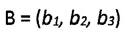
- the present invention uses a digital way to present a color value which creates a clear definition for every preset action. Only when certain conditions are fulfilled, the dyeing machine will run according to preset parameters. For example, by setting an end point of rinsing process as a fixed color C: (c 1 , c 2 , c 3 ). When the rinsing process is running, the concentration decreases and the color becomes paler. When the reading from color detector has the same value as the preset value, i.e. it matches c 1 , c 2 and c 3 , the system defines an end of rinsing and execute any related actions, like shutting injection valves of cleansing agent.
- the major feature of this invention is utilizing refracted ray for data analysis to compute the dye concentration, the precision is proven a lot better than existing techniques.
- the present invention can directly obtain color data for the reference of dyeing and cleansing, raising and reliability and precisely predicts the usage of dye and cleansing agent, prevents unnecessary consumption, saves cost.
- the embodiment of the present invention is realized by a color monitoring system on a dyeing machine.
- Figure 1 is a cross-sectional view of the device used in this embodiment.
- a chamber inlet (3) is located at one side of the wall of measurement chamber (2), while the chamber outlet (4) is at the ceiling of said chamber.
- a silicone ring (12) is placed between the outer flange and the light beam emitter, as well as the other end on the light beam receiver. (The outer flange on left hand side is in general appearance while the right hand side is sectioned.)
- a cleansing pipe (6) is connected to the ceiling of measurement chamber.
- the chamber inlet and outlet connect to the dye circulation of a dyeing machine, where the additional pipeline forms a secondary circulation in part of the main one.
- the chamber inlet and outlet are positioned respectively on a side and at the top such that when dye liquor enters the chamber, the light ray emitted from the light beam emitter (7) pierces through glass (5A) and the dye in chamber, and is received by the light beam receiver (8) via glass (5B) on the opposite side of chamber.
- the arrow in figure 1 points the light ray travelling direction.
- the light beam emitted from the emitter travels along the way from the hole in middle of outer flange, the mirror, the hole on inner flange, the dye liquor, to the other end of chamber with holes and glass, eventually received by the receiver (8).
- the information gathered is processed by the controller for further analysis.
- the embodiment applies color detection on dyeing machines, integrating with the computer to control and adjust dye liquor by color data, whilst executing any preset actions or programs.
- the above actions include any functional execution, for example, a drain step controlled by color recognition.
- the liquor in a vessel could be drained in separated channel, by configuring multiple outlets connected to the vessel such that the liquor could be processed by different concentration in time. Drained liquor in low concentration can even be recycled to lower the drainage treatment cost.
- the concentration of liquor is measured by its color and the liquor itself is diverted into corresponding outlets by its varying concentration in time, controlled by the computer.
- one outlet could be opened for draining once the rinsing process starts, where the dye concentration at the moment is considerably high.
- another drainage outlet is used. Hence the treatment could be simplified.
- the controller executes a default rinsing program, wherein the action is to open the fill valve and drain valve simultaneously.
- the liquor is diluted whilst the circulation pump stirs the liquor in the vessel.
- the data recorded on the color detection device keeps changing as the liquor is diluted.
- a default value is set in the controller such that when said device read the same value, the rinsing program stops. Then the liquor concentration is said to reach the required level, in other words rinsing is complete.
- the aforesaid color value is set by the operator such that the same rinsing result can be achieved in the next batch, hence automation is fulfilled.
- a valve For example, to set a valve being opened when certain color level is reached, allowing external solvent to enter the system and change the liquor nature is considered an automated dye conditioning.
- an automated dye conditioning By understanding the relation between dye color and its chemical status, one could judge precisely the situation and inject additives according to the recipe in specific moment, instead of determining the right time by human observation which causes error.
- a valve could be closed when certain color level is reached, to separate the dye from external influences which may further cause changes to the dye, maintaining it in desired condition, so as to execute common processes like dyeing and rinsing.
- one injection point and two drainage points are configured in the dye circulation system, controlled by fill valve (17), drainage valve (18) and second drainage valve (19) respectively.
- the three valves are controlled by the controller (15), and the dye condition can be altered by the combination of switches between these valves, determined by the color value read from the color detection device. For example, to use different drainage valve for draining dye in different color, meanwhile opening the fill valve to dilute the solvent in rinsing.
- Any actuators other than valves can also be a terminal device serving for the color detection system.
- a lamp for indication is also a common design.
- the present invention can also be considered as a sensor on a dyeing machine.
Landscapes
- Physics & Mathematics (AREA)
- Textile Engineering (AREA)
- Engineering & Computer Science (AREA)
- Biochemistry (AREA)
- Chemical & Material Sciences (AREA)
- Analytical Chemistry (AREA)
- Life Sciences & Earth Sciences (AREA)
- General Health & Medical Sciences (AREA)
- General Physics & Mathematics (AREA)
- Immunology (AREA)
- Pathology (AREA)
- Health & Medical Sciences (AREA)
- Spectroscopy & Molecular Physics (AREA)
- Treatment Of Fiber Materials (AREA)
- Coloring (AREA)
Abstract
Description
- This invention relates to a monitoring technique in fabric dyeing, in particular a method for rinsing control in dyeing process.
- In ordinary fabric dyeing technique, fabric is dyed by dye liquor inside a vessel. The dye liquor is drained after dyeing yet there is always residue remained on the fabric. Cleansing agent is filled into the vessel to wash away the dye on the fabric. This process is repeated until the fabric is clean to unload. However the knowhow to determine the color during dyeing and rinsing is so important that it would affect the quality and production cost. In traditional ways, one relies on past experience to decide the quantity of dye or cleansing agent and the process duration, yet it is not precise and unrepeatable.
- Researches discovered that the sodium chloride level in dye liquor is directly related to its concentration, and the way is simple to track this level, such that there already have been a method to monitor chloride level in real time during rinsing and estimate its concentration. When it breaches certain level the rinsing process will repeat until it is diluted. However the same level in two different colors may represent different concentration. The above method has a defect that cannot truly reflect the concentration of dye liquor.
- Thus the dyeing industry is desperate for a new measurement adaptable in pressurized environment to monitor dye concentration.
- The present invention is introduced to address the above problem and to provide a new rinsing control and monitoring method.
- The steps of the present invention are:
- Firstly introduce dye liquor to a measuring chamber from the vessel containing dye liquor on a dyeing machine,
- Secondly a light beam emitted from a lighting device pierces through the chamber and the dye liquor within while a receiver gathers the refracted rays,
- Thirdly a control system analyzes the signal sent from the receiver and defines the concentration by its color.
- The control system would selectively drain out the vessel in different pipes judging by the liquor concentration or other indicators configured.
- The control system could also execute various actions when the required concentration is reached.
- The monitoring and control method for rinsing process on a dyeing machine in this invention is characterized in that the light source from the device is a white LED light.
- The monitoring and control method for rinsing process on a dyeing machine in this invention is characterized in that the said receiver is a RGB sensor.
- The monitoring and control method for rinsing process on a dyeing machine in this invention is characterized in that the measuring chamber has valves on both inlet and outlet, such that the chamber is sealed for a period of time before it reopens, to discretely measure dye samples.
- The monitoring and control method for rinsing process on a dyeing machine in this invention is characterized in that the dye liquor is a kind of water solvent for fabric cleansing.
- The monitoring and control method for rinsing process on a dyeing machine in this invention is characterized in that the preset concentration value for triggering functions is saved and controlled by computer.
- Differing from recent technologies, the present method gather color data in real time to precisely compute and predict dye color's change through time.
- The visible spectrum is formed by three basic colors: red, green and blue. The color data recorded is also represented by these indicators. The changes in these indicators represent the color change. For instance, dye liquor is injected into the vessel in dyeing process, and the color keeps changing from a color A to another color B eventually, represented in the following way:

- In form of a matrix, the RGB index is recorded wherein the three elements in the matrix respectively represent the RGB value. Assume a1 and b1 are correspondingly the red index from color A and B, the difference between two values is the variance of red index. Since the quantity of solvent and dye are known as well as the duration, a mathematical model can be formed base on the above factors to show the influence of different dye on changing the liquor color, and show the relationship between solvent, dye and time. The algorithm is stored in the operation system representing the characteristics of dyes such that time and dosage can be estimated for desired color.
- A RGB sensor in the control circuit is used for monitoring the RGB index of dye. It is a light sensor that gathers light refracted from the dye and converts into three voltage signals (v1, v2, v3). A mathematic model can be constructed by massive collection of data and statistical analysis. For instance the color index (a1, a2, a3) representing a color A, its function can be written as:


- In other words, the controller can compute the RGB index of dye by reading the voltage signals. However the received light beams are affected by the intensity of original white rays. Given the same color of dye, the receiver would have different readings if the light intensity is changed, and wrongly recognize as a darker or brighter color, making an error. Hence the intensity factor is considered in the math model such that the computed value has a compensation included for a precise result. It could be further interpreted as:


- The present invention detects the RGB index of dye liquor to monitor its status, and implement control to its dyeing and rinsing process via the computer.
- Traditionally in dyeing and finishing process, men uses their eyes to determine whether should the rinsing process end, a different decision can be made even in several patches of same color. The present invention uses a digital way to present a color value which creates a clear definition for every preset action. Only when certain conditions are fulfilled, the dyeing machine will run according to preset parameters. For example, by setting an end point of rinsing process as a fixed color C: (c1, c2, c3). When the rinsing process is running, the concentration decreases and the color becomes paler. When the reading from color detector has the same value as the preset value, i.e. it matches c1, c2 and c3, the system defines an end of rinsing and execute any related actions, like shutting injection valves of cleansing agent.
- The major feature of this invention is utilizing refracted ray for data analysis to compute the dye concentration, the precision is proven a lot better than existing techniques.
- The present invention can directly obtain color data for the reference of dyeing and cleansing, raising and reliability and precisely predicts the usage of dye and cleansing agent, prevents unnecessary consumption, saves cost.
-
-
Figure 1 is the embodiment of the present invention. -
Figure 2 is the diagram showing the present invention applying on a dyeing machine. -
Figure 3 is the diagram showing the prevent invention in control of multiple drainage valves on a dyeing machine. - Wherein:
- 1.
- Monitoring device
- 2.
- Measurement chamber
- 3.
- Chamber inlet
- 4.
- Chamber outlet
- 5.
- (Incl. 5A, 5B) glass
- 6.
- Cleansing pipe
- 7.
- Light beam emitter
- 8.
- Light beam receiver
- 9.
- Inner flange
- 10.
- Outer flange
- 11.
- Gasket
- 12.
- Silicone seal
- 13.
- Dyeing machine
- 14.
- Dye circulation
- 15.
- Controller
- 16.
- Filter
- 17.
- Fill valve
- 18.
- Drain valve
- 19.
- Second drain valve
- The following further describes the present invention by figures and embodiments.
- The embodiment of the present invention is realized by a color monitoring system on a dyeing machine.
-
Figure 1 is a cross-sectional view of the device used in this embodiment. - In
figure 1 , a chamber inlet (3) is located at one side of the wall of measurement chamber (2), while the chamber outlet (4) is at the ceiling of said chamber. There are inner flanges (9) on both sides of chamber, where a pair of outer flanges (10) fits with them and connect to each other with screws. There are glasses (5A) and (5B) between the inner flange and outer flange, and there are also gaskets (11) between the glass and each flange to prevent leakage. There are light beam emitter (7) and light beam receiver (8) on the outer sides of outer flanges. A silicone ring (12) is placed between the outer flange and the light beam emitter, as well as the other end on the light beam receiver. (The outer flange on left hand side is in general appearance while the right hand side is sectioned.) A cleansing pipe (6) is connected to the ceiling of measurement chamber. - The chamber inlet and outlet connect to the dye circulation of a dyeing machine, where the additional pipeline forms a secondary circulation in part of the main one. The chamber inlet and outlet are positioned respectively on a side and at the top such that when dye liquor enters the chamber, the light ray emitted from the light beam emitter (7) pierces through glass (5A) and the dye in chamber, and is received by the light beam receiver (8) via glass (5B) on the opposite side of chamber. The arrow in
figure 1 points the light ray travelling direction. - The chamber inlet connects to the dye circulation. Dye liquor enters the chamber via the inlet, as a batch of sample for the color detection device. The dye leaves the chamber via the outlet (4).
- As shown by the arrow in
figure 1 , when the chamber is filled with dye liquor, the light beam emitted from the emitter travels along the way from the hole in middle of outer flange, the mirror, the hole on inner flange, the dye liquor, to the other end of chamber with holes and glass, eventually received by the receiver (8). The information gathered is processed by the controller for further analysis. - The embodiment applies color detection on dyeing machines, integrating with the computer to control and adjust dye liquor by color data, whilst executing any preset actions or programs.
- The above actions include any functional execution, for example, a drain step controlled by color recognition. The liquor in a vessel could be drained in separated channel, by configuring multiple outlets connected to the vessel such that the liquor could be processed by different concentration in time. Drained liquor in low concentration can even be recycled to lower the drainage treatment cost. In other words, the concentration of liquor is measured by its color and the liquor itself is diverted into corresponding outlets by its varying concentration in time, controlled by the computer. To implement such a way, one outlet could be opened for draining once the rinsing process starts, where the dye concentration at the moment is considerably high. When the liquor is diluted, another drainage outlet is used. Hence the treatment could be simplified.
- To further illustrate the action, an embodiment is explained. Whenever the fabric is dyed, the liquor concentration in the vessel is often high, which is also reflected from the color detection device. The controller executes a default rinsing program, wherein the action is to open the fill valve and drain valve simultaneously. The liquor is diluted whilst the circulation pump stirs the liquor in the vessel. The data recorded on the color detection device keeps changing as the liquor is diluted. A default value is set in the controller such that when said device read the same value, the rinsing program stops. Then the liquor concentration is said to reach the required level, in other words rinsing is complete. The aforesaid color value is set by the operator such that the same rinsing result can be achieved in the next batch, hence automation is fulfilled.
- In the embodiment shown in
figure 2 , there is a dyeing machine (13) with a color detection device (1). Said dyeing machine includes a vessel containing dye liquor and fabric, wherein the vessel has a dye circulation (14) to let liquor flow inside the machine, and a circulation pump to drive the liquor flow. A filter (16) is installed in the circulation before liquor flowing into the color detection device, filtering the lint from the system. - The dyeing vessel connects to a fluid inlet that is used for injecting dye liquor, cleansing agents or any other chemicals; and a fluid outlet for discharge. Said inlet and outlet have respectively an inlet valve (17) and an outlet (18), wherein their switches are connected to the controller of dyeing machine (15). The color detection device lies on the dye circulation such that dye liquor could pass through the system. Said device read the color data and send it to the central processing unit where the algorithm converts the data into relative commands to control the valves. The relation between color data and valve opening can be altered by changing coefficients in the mathematic model for desired effects.
Figure 3 shows a configuration of dyeing machine having two draining valves. Having more than one draining valve could enhance the applicability of color detection system. It is applied by diagnosing the dye color inside the detection chamber to determine the valve action, particularly in dyeing and draining process. For instance, a preset color D: (d1, d2, d3). The color detection device sends the RGB value of dye instantly recorded to the control system, until the measured value matches the RGB index of color D, i.e. d1, d2 and d3. The system then terminates the process and executes any actions related to the termination, for example valves are involved as shown infigure 3 . By controlling valves base on color recognition, one could change or maintain the status of dye effectively. - For example, to set a valve being opened when certain color level is reached, allowing external solvent to enter the system and change the liquor nature is considered an automated dye conditioning. By understanding the relation between dye color and its chemical status, one could judge precisely the situation and inject additives according to the recipe in specific moment, instead of determining the right time by human observation which causes error. Vice versa, a valve could be closed when certain color level is reached, to separate the dye from external influences which may further cause changes to the dye, maintaining it in desired condition, so as to execute common processes like dyeing and rinsing.
- In
figure 3 , one injection point and two drainage points are configured in the dye circulation system, controlled by fill valve (17), drainage valve (18) and second drainage valve (19) respectively. The three valves are controlled by the controller (15), and the dye condition can be altered by the combination of switches between these valves, determined by the color value read from the color detection device. For example, to use different drainage valve for draining dye in different color, meanwhile opening the fill valve to dilute the solvent in rinsing. These are foreseeable for a person in the field, where the key is the control relationship between color detection and the use of actuators on the machine. Undoubtedly in the central processing unit of a dyeing machine, it is not only the valves being controlled. Any actuators other than valves can also be a terminal device serving for the color detection system. For example, a lamp for indication is also a common design. The present invention can also be considered as a sensor on a dyeing machine.
Claims (7)
- A monitoring and control method for rinsing process on a dyeing machine, wherein the steps are:Firstly introduce dye liquor to a measuring chamber from the vessel containing dye liquor on a dyeing machine,Secondly a light beam emitted from a lighting device pierces through the chamber and dye liquor within while a receiver gathers the refracted rays,Thirdly the receiver connects to the control system, where the signal is analyzed and defines the concentration by its color.The control system would selectively drain out the vessel in different pipes judging by the liquor concentration or other indicators configured.The control system could also execute various actions when the required concentration is reached.
- The monitoring and control method for rinsing process on a dyeing machine according to claim 1, characterized in that the light beam emitted from the lighting device is a white LED light.
- The monitoring and control method for rinsing process on a dyeing machine according to claim 1, characterized in that the said receiver is a RGB sensor.
- The monitoring and control method for rinsing process on a dyeing machine according to claim 1, characterized in that the measuring chamber has valves on both ends, such that the chamber is sealed for a period before it reopens, to measure discrete color samples.
- The monitoring and control method for rinsing process on a dyeing machine according to claim 1, characterized in that the dye liquor is a kind of water solvent for fabric cleansing.
- The monitoring and control method for rinsing process on a dyeing machine according to claim 1, characterized in that the preset concentration value to trigger actions is saved and controlled by computer.
- The monitoring and control method for rinsing process on a dyeing machine according to claim 1, characterized in that the steps are included that the detector is calibrated, when dye liquor is injected into the measuring chamber before start and after finish every batch dyeing process.
Applications Claiming Priority (1)
| Application Number | Priority Date | Filing Date | Title |
|---|---|---|---|
| PCT/CN2013/075225 WO2014179930A1 (en) | 2013-05-06 | 2013-05-06 | Detecting and controlling method for rinsing procedure of dyeing machine |
Publications (2)
| Publication Number | Publication Date |
|---|---|
| EP2995709A1 true EP2995709A1 (en) | 2016-03-16 |
| EP2995709A4 EP2995709A4 (en) | 2017-02-22 |
Family
ID=51866600
Family Applications (1)
| Application Number | Title | Priority Date | Filing Date |
|---|---|---|---|
| EP13884293.5A Withdrawn EP2995709A4 (en) | 2013-05-06 | 2013-05-06 | Detecting and controlling method for rinsing procedure of dyeing machine |
Country Status (3)
| Country | Link |
|---|---|
| EP (1) | EP2995709A4 (en) |
| IN (1) | IN2015DN01866A (en) |
| WO (1) | WO2014179930A1 (en) |
Cited By (3)
| Publication number | Priority date | Publication date | Assignee | Title |
|---|---|---|---|---|
| CN109056227A (en) * | 2018-10-12 | 2018-12-21 | 绍兴文理学院 | A kind of cloth dip dyeing equipment |
| CN109162045A (en) * | 2018-10-12 | 2019-01-08 | 绍兴文理学院 | It is a kind of for disseminating the equipment of cloth |
| CN115434092A (en) * | 2021-06-03 | 2022-12-06 | 财团法人纺织产业综合研究所 | Regulation and control water charging system |
Families Citing this family (3)
| Publication number | Priority date | Publication date | Assignee | Title |
|---|---|---|---|---|
| CN109137327B (en) * | 2018-10-26 | 2023-10-13 | 浙江俏尔婷婷服饰有限公司 | Garment roller dyeing machine with online pH value detection device and detection method thereof |
| TWI693323B (en) * | 2019-11-27 | 2020-05-11 | 財團法人紡織產業綜合研究所 | Dyeing apprutus and method for predicting washing time for cloth |
| CN113638161A (en) * | 2021-08-03 | 2021-11-12 | 董秀香 | Energy-saving cloth dyeing machine convenient to mix colours fast |
Family Cites Families (11)
| Publication number | Priority date | Publication date | Assignee | Title |
|---|---|---|---|---|
| US3088479A (en) * | 1958-02-13 | 1963-05-07 | Proctor & Schwartz Inc | System of color monitoring |
| BE631668A (en) * | 1962-05-03 | |||
| JP3125158B2 (en) * | 1992-03-17 | 2001-01-15 | セーレン株式会社 | Continuous padding dyeing equipment |
| DE10014965C1 (en) * | 2000-03-25 | 2002-02-28 | Monforts Textilmaschinen Gmbh | Single-color dyeing of a fabric material in a padding mangle, uses a color monitor which takes a single segment of the diffused reflected color spectrum to control the mangle roller operation |
| ITMI20021192A1 (en) * | 2002-05-31 | 2003-12-01 | Loris Bellini S P A | DYEING MACHINE WITH AUTOMATIC IN-LINE CONTROL OF BATH EXHAUST |
| WO2005040482A1 (en) * | 2003-10-21 | 2005-05-06 | Georges Cornuejols | Method and device for controlling a dyeing machine |
| JP5449828B2 (en) * | 2009-04-01 | 2014-03-19 | セーレン株式会社 | Processing method of fiber material |
| CN201424579Y (en) * | 2009-06-10 | 2010-03-17 | 刘孝浩 | Automatic monitoring and feeding device of dye vat |
| EP2511693A1 (en) * | 2011-04-13 | 2012-10-17 | F. Hoffmann-La Roche AG | Analysis System with a spectrally controlled light source |
| CN102560940B (en) * | 2012-01-11 | 2013-10-30 | 浙江理工大学 | Device and method for online detection of dye liquor concentration by dual-wavelength spectrophotometry |
| CN202430470U (en) * | 2012-01-11 | 2012-09-12 | 浙江理工大学 | On-line detection device for dye concentration with dual-wavelength spectrophotometric method |
-
2013
- 2013-05-06 EP EP13884293.5A patent/EP2995709A4/en not_active Withdrawn
- 2013-05-06 WO PCT/CN2013/075225 patent/WO2014179930A1/en not_active Ceased
-
2015
- 2015-03-09 IN IN1866DEN2015 patent/IN2015DN01866A/en unknown
Non-Patent Citations (1)
| Title |
|---|
| See references of WO2014179930A1 * |
Cited By (5)
| Publication number | Priority date | Publication date | Assignee | Title |
|---|---|---|---|---|
| CN109056227A (en) * | 2018-10-12 | 2018-12-21 | 绍兴文理学院 | A kind of cloth dip dyeing equipment |
| CN109162045A (en) * | 2018-10-12 | 2019-01-08 | 绍兴文理学院 | It is a kind of for disseminating the equipment of cloth |
| CN109056227B (en) * | 2018-10-12 | 2020-09-29 | 绍兴文理学院 | Cloth dip-dyeing equipment |
| CN109162045B (en) * | 2018-10-12 | 2020-10-16 | 绍兴文理学院 | A device for dip-dyeing cloth |
| CN115434092A (en) * | 2021-06-03 | 2022-12-06 | 财团法人纺织产业综合研究所 | Regulation and control water charging system |
Also Published As
| Publication number | Publication date |
|---|---|
| IN2015DN01866A (en) | 2015-07-31 |
| WO2014179930A1 (en) | 2014-11-13 |
| EP2995709A4 (en) | 2017-02-22 |
Similar Documents
| Publication | Publication Date | Title |
|---|---|---|
| EP2995709A1 (en) | Detecting and controlling method for rinsing procedure of dyeing machine | |
| HK1200909A1 (en) | A method for rinsing control and measurement on fabric dyeing machines | |
| CA1327509C (en) | Titrating apparatus | |
| TWI555898B (en) | Detection and Control of Washing Procedure for Dyeing Machine | |
| EP3187644B1 (en) | Washing machine having reminding function for preventing clothing from fading, and method | |
| CN113514601A (en) | A kind of online detection method and system of permanganate index | |
| CN218629695U (en) | Potentiometric and photometric titration integrated permanganate index analyzer | |
| CN111272675A (en) | Dye liquor detection device | |
| CN102535071B (en) | Online detection method for dye liquor components of bundle type dye machine on basis of programmable logic controller (PLC) | |
| CN117491557A (en) | A device and method for online measurement of water quality alkalinity | |
| EP2995931A1 (en) | Dye liquor color detection apparatus for dyeing machine | |
| CN1594711A (en) | Rinsing method for washing machine and washing machine with the same | |
| CN103924419B (en) | Washing solution online detection method and washing device | |
| CN104142180B (en) | Dye liquor color detection device for dyeing machine | |
| CN115672890B (en) | Gas sensor cleaning device and cleaning method | |
| KR100860545B1 (en) | Dissolved oxygen automatic measuring device and method | |
| WO2025097873A1 (en) | Device and measurement method for in-line water hardness measurement | |
| CN111141728A (en) | Automatic titration end point judgment method | |
| CN205643158U (en) | Multiplying power method sewage colourity apparatus | |
| CN211785383U (en) | Automatic titrator based on color sensor | |
| US5649560A (en) | Combined measuring and injecting flow cell | |
| US20010044153A1 (en) | Automatic liquid analyser and quality controller | |
| US20070234486A1 (en) | Method and Device for Controlling a Dyeing Machine | |
| CN203231926U (en) | Ultraviolet digester and automatic analyzer for quality of heavy metal containing water | |
| EP3910330B1 (en) | Water quality analyzer |
Legal Events
| Date | Code | Title | Description |
|---|---|---|---|
| PUAI | Public reference made under article 153(3) epc to a published international application that has entered the european phase |
Free format text: ORIGINAL CODE: 0009012 |
|
| 17P | Request for examination filed |
Effective date: 20141209 |
|
| AK | Designated contracting states |
Kind code of ref document: A1 Designated state(s): AL AT BE BG CH CY CZ DE DK EE ES FI FR GB GR HR HU IE IS IT LI LT LU LV MC MK MT NL NO PL PT RO RS SE SI SK SM TR |
|
| AX | Request for extension of the european patent |
Extension state: BA ME |
|
| DAX | Request for extension of the european patent (deleted) | ||
| A4 | Supplementary search report drawn up and despatched |
Effective date: 20170120 |
|
| RIC1 | Information provided on ipc code assigned before grant |
Ipc: G01N 21/05 20060101ALI20170116BHEP Ipc: G01N 21/01 20060101ALI20170116BHEP Ipc: D06B 23/00 20060101AFI20170116BHEP Ipc: D06B 23/20 20060101ALI20170116BHEP Ipc: D06B 23/28 20060101ALI20170116BHEP |
|
| STAA | Information on the status of an ep patent application or granted ep patent |
Free format text: STATUS: REQUEST FOR EXAMINATION WAS MADE |
|
| STAA | Information on the status of an ep patent application or granted ep patent |
Free format text: STATUS: THE APPLICATION IS DEEMED TO BE WITHDRAWN |
|
| 18D | Application deemed to be withdrawn |
Effective date: 20170818 |