EP2995771B1 - Turbofantriebwerk und stator - Google Patents
Turbofantriebwerk und stator Download PDFInfo
- Publication number
- EP2995771B1 EP2995771B1 EP15183680.6A EP15183680A EP2995771B1 EP 2995771 B1 EP2995771 B1 EP 2995771B1 EP 15183680 A EP15183680 A EP 15183680A EP 2995771 B1 EP2995771 B1 EP 2995771B1
- Authority
- EP
- European Patent Office
- Prior art keywords
- airfoil
- diameter edge
- edge
- inner diameter
- outer diameter
- Prior art date
- Legal status (The legal status is an assumption and is not a legal conclusion. Google has not performed a legal analysis and makes no representation as to the accuracy of the status listed.)
- Active
Links
Images


Classifications
-
- F—MECHANICAL ENGINEERING; LIGHTING; HEATING; WEAPONS; BLASTING
- F01—MACHINES OR ENGINES IN GENERAL; ENGINE PLANTS IN GENERAL; STEAM ENGINES
- F01D—NON-POSITIVE DISPLACEMENT MACHINES OR ENGINES, e.g. STEAM TURBINES
- F01D5/00—Blades; Blade-carrying members; Heating, heat-insulating, cooling or antivibration means on the blades or the members
- F01D5/12—Blades
- F01D5/14—Form or construction
- F01D5/141—Shape, i.e. outer, aerodynamic form
- F01D5/142—Shape, i.e. outer, aerodynamic form of the blades of successive rotor or stator blade-rows
-
- F—MECHANICAL ENGINEERING; LIGHTING; HEATING; WEAPONS; BLASTING
- F01—MACHINES OR ENGINES IN GENERAL; ENGINE PLANTS IN GENERAL; STEAM ENGINES
- F01D—NON-POSITIVE DISPLACEMENT MACHINES OR ENGINES, e.g. STEAM TURBINES
- F01D9/00—Stators
- F01D9/02—Nozzles; Nozzle boxes; Stator blades; Guide conduits, e.g. individual nozzles
- F01D9/04—Nozzles; Nozzle boxes; Stator blades; Guide conduits, e.g. individual nozzles forming ring or sector
- F01D9/041—Nozzles; Nozzle boxes; Stator blades; Guide conduits, e.g. individual nozzles forming ring or sector using blades
-
- F—MECHANICAL ENGINEERING; LIGHTING; HEATING; WEAPONS; BLASTING
- F02—COMBUSTION ENGINES; HOT-GAS OR COMBUSTION-PRODUCT ENGINE PLANTS
- F02C—GAS-TURBINE PLANTS; AIR INTAKES FOR JET-PROPULSION PLANTS; CONTROLLING FUEL SUPPLY IN AIR-BREATHING JET-PROPULSION PLANTS
- F02C3/00—Gas-turbine plants characterised by the use of combustion products as the working fluid
- F02C3/04—Gas-turbine plants characterised by the use of combustion products as the working fluid having a turbine driving a compressor
-
- F—MECHANICAL ENGINEERING; LIGHTING; HEATING; WEAPONS; BLASTING
- F04—POSITIVE - DISPLACEMENT MACHINES FOR LIQUIDS; PUMPS FOR LIQUIDS OR ELASTIC FLUIDS
- F04D—NON-POSITIVE-DISPLACEMENT PUMPS
- F04D29/00—Details, component parts, or accessories
- F04D29/26—Rotors specially for elastic fluids
- F04D29/32—Rotors specially for elastic fluids for axial flow pumps
- F04D29/321—Rotors specially for elastic fluids for axial flow pumps for axial flow compressors
- F04D29/324—Blades
-
- F—MECHANICAL ENGINEERING; LIGHTING; HEATING; WEAPONS; BLASTING
- F04—POSITIVE - DISPLACEMENT MACHINES FOR LIQUIDS; PUMPS FOR LIQUIDS OR ELASTIC FLUIDS
- F04D—NON-POSITIVE-DISPLACEMENT PUMPS
- F04D29/00—Details, component parts, or accessories
- F04D29/40—Casings; Connections of working fluid
- F04D29/52—Casings; Connections of working fluid for axial pumps
- F04D29/54—Fluid-guiding means, e.g. diffusers
- F04D29/541—Specially adapted for elastic fluid pumps
- F04D29/542—Bladed diffusers
- F04D29/544—Blade shapes
-
- F—MECHANICAL ENGINEERING; LIGHTING; HEATING; WEAPONS; BLASTING
- F05—INDEXING SCHEMES RELATING TO ENGINES OR PUMPS IN VARIOUS SUBCLASSES OF CLASSES F01-F04
- F05D—INDEXING SCHEME FOR ASPECTS RELATING TO NON-POSITIVE-DISPLACEMENT MACHINES OR ENGINES, GAS-TURBINES OR JET-PROPULSION PLANTS
- F05D2220/00—Application
- F05D2220/30—Application in turbines
- F05D2220/32—Application in turbines in gas turbines
- F05D2220/323—Application in turbines in gas turbines for aircraft propulsion, e.g. jet engines
-
- F—MECHANICAL ENGINEERING; LIGHTING; HEATING; WEAPONS; BLASTING
- F05—INDEXING SCHEMES RELATING TO ENGINES OR PUMPS IN VARIOUS SUBCLASSES OF CLASSES F01-F04
- F05D—INDEXING SCHEME FOR ASPECTS RELATING TO NON-POSITIVE-DISPLACEMENT MACHINES OR ENGINES, GAS-TURBINES OR JET-PROPULSION PLANTS
- F05D2240/00—Components
- F05D2240/10—Stators
- F05D2240/12—Fluid guiding means, e.g. vanes
- F05D2240/121—Fluid guiding means, e.g. vanes related to the leading edge of a stator vane
-
- F—MECHANICAL ENGINEERING; LIGHTING; HEATING; WEAPONS; BLASTING
- F05—INDEXING SCHEMES RELATING TO ENGINES OR PUMPS IN VARIOUS SUBCLASSES OF CLASSES F01-F04
- F05D—INDEXING SCHEME FOR ASPECTS RELATING TO NON-POSITIVE-DISPLACEMENT MACHINES OR ENGINES, GAS-TURBINES OR JET-PROPULSION PLANTS
- F05D2240/00—Components
- F05D2240/10—Stators
- F05D2240/12—Fluid guiding means, e.g. vanes
- F05D2240/122—Fluid guiding means, e.g. vanes related to the trailing edge of a stator vane
-
- F—MECHANICAL ENGINEERING; LIGHTING; HEATING; WEAPONS; BLASTING
- F05—INDEXING SCHEMES RELATING TO ENGINES OR PUMPS IN VARIOUS SUBCLASSES OF CLASSES F01-F04
- F05D—INDEXING SCHEME FOR ASPECTS RELATING TO NON-POSITIVE-DISPLACEMENT MACHINES OR ENGINES, GAS-TURBINES OR JET-PROPULSION PLANTS
- F05D2240/00—Components
- F05D2240/20—Rotors
- F05D2240/30—Characteristics of rotor blades, i.e. of any element transforming dynamic fluid energy to or from rotational energy and being attached to a rotor
- F05D2240/301—Cross-sectional characteristics
-
- F—MECHANICAL ENGINEERING; LIGHTING; HEATING; WEAPONS; BLASTING
- F05—INDEXING SCHEMES RELATING TO ENGINES OR PUMPS IN VARIOUS SUBCLASSES OF CLASSES F01-F04
- F05D—INDEXING SCHEME FOR ASPECTS RELATING TO NON-POSITIVE-DISPLACEMENT MACHINES OR ENGINES, GAS-TURBINES OR JET-PROPULSION PLANTS
- F05D2240/00—Components
- F05D2240/20—Rotors
- F05D2240/30—Characteristics of rotor blades, i.e. of any element transforming dynamic fluid energy to or from rotational energy and being attached to a rotor
- F05D2240/303—Characteristics of rotor blades, i.e. of any element transforming dynamic fluid energy to or from rotational energy and being attached to a rotor related to the leading edge of a rotor blade
-
- F—MECHANICAL ENGINEERING; LIGHTING; HEATING; WEAPONS; BLASTING
- F05—INDEXING SCHEMES RELATING TO ENGINES OR PUMPS IN VARIOUS SUBCLASSES OF CLASSES F01-F04
- F05D—INDEXING SCHEME FOR ASPECTS RELATING TO NON-POSITIVE-DISPLACEMENT MACHINES OR ENGINES, GAS-TURBINES OR JET-PROPULSION PLANTS
- F05D2240/00—Components
- F05D2240/20—Rotors
- F05D2240/30—Characteristics of rotor blades, i.e. of any element transforming dynamic fluid energy to or from rotational energy and being attached to a rotor
- F05D2240/304—Characteristics of rotor blades, i.e. of any element transforming dynamic fluid energy to or from rotational energy and being attached to a rotor related to the trailing edge of a rotor blade
-
- F—MECHANICAL ENGINEERING; LIGHTING; HEATING; WEAPONS; BLASTING
- F05—INDEXING SCHEMES RELATING TO ENGINES OR PUMPS IN VARIOUS SUBCLASSES OF CLASSES F01-F04
- F05D—INDEXING SCHEME FOR ASPECTS RELATING TO NON-POSITIVE-DISPLACEMENT MACHINES OR ENGINES, GAS-TURBINES OR JET-PROPULSION PLANTS
- F05D2240/00—Components
- F05D2240/35—Combustors or associated equipment
-
- F—MECHANICAL ENGINEERING; LIGHTING; HEATING; WEAPONS; BLASTING
- F05—INDEXING SCHEMES RELATING TO ENGINES OR PUMPS IN VARIOUS SUBCLASSES OF CLASSES F01-F04
- F05D—INDEXING SCHEME FOR ASPECTS RELATING TO NON-POSITIVE-DISPLACEMENT MACHINES OR ENGINES, GAS-TURBINES OR JET-PROPULSION PLANTS
- F05D2250/00—Geometry
- F05D2250/70—Shape
- F05D2250/71—Shape curved
-
- Y—GENERAL TAGGING OF NEW TECHNOLOGICAL DEVELOPMENTS; GENERAL TAGGING OF CROSS-SECTIONAL TECHNOLOGIES SPANNING OVER SEVERAL SECTIONS OF THE IPC; TECHNICAL SUBJECTS COVERED BY FORMER USPC CROSS-REFERENCE ART COLLECTIONS [XRACs] AND DIGESTS
- Y02—TECHNOLOGIES OR APPLICATIONS FOR MITIGATION OR ADAPTATION AGAINST CLIMATE CHANGE
- Y02T—CLIMATE CHANGE MITIGATION TECHNOLOGIES RELATED TO TRANSPORTATION
- Y02T50/00—Aeronautics or air transport
- Y02T50/60—Efficient propulsion technologies, e.g. for aircraft
Definitions
- the present invention concerns an airfoil for a fan exit stator of a gas turbine engine.
- a gas turbine engine includes a compressor section with multiple rows or stages of stator vanes and rotor blades.
- the turbine rotor blades drive the compressor and an electric generator to generate electrical power.
- Some gas turbine engines include a fan positioned forward of the entrance to the compressor. This fan can provide additional propulsion to the gas turbine engine.
- the fan rotates in order to provide propulsion.
- the fan may create high turning of the airflow and may create tangential or circumferential air flow.
- a set of stator blades may be provided at the inlet to the compressor in order to turn the air exiting the fan to an intended direction. This set of stator blades may be referred to as a fan exit stator.
- EP 0887513 A2 discloses another prior art airfoil.
- the present invention provides an airfoil in accordance with claim 1.
- forward and aft directions are defined in reference to the predominate flow direction through a gas turbine engine, with air generally flowing from the forward direction toward the aft direction.
- Gas turbine engine 20 may be a two-spool turbofan that generally incorporates a fan section 22, a compressor section 24, a combustor section 26 and a turbine section 28.
- Alternative engines may include, for example, an augmentor section among other systems or features.
- fan section 22 can drive air along a bypass flow-path B while compressor section 24 can drive air along a core flow-path C for compression and communication into combustor section 26 then expansion through turbine section 28.
- turbofan gas turbine engine 20 depicted as a turbofan gas turbine engine 20 herein, it should be understood that the concepts described herein are not limited to use with turbofans as the teachings may be applied to other types of turbine engines including one-, two- and three-spool architectures.
- Gas turbine engine 20 may generally comprise a low speed spool 30 and a high speed spool 32 mounted for rotation about an engine central longitudinal axis A-A' relative to an engine static structure 36 via several bearing systems 38, 38-1, and 38-2. It should be understood that various bearing systems 38 at various locations may alternatively or additionally be provided, including for example, bearing system 38, bearing system 38-1, and bearing system 38-2.
- Low speed spool 30 may generally comprise an inner shaft 40 that interconnects a fan 42, a low pressure (or first) compressor section 44 and a low pressure (or first) turbine section 46.
- Inner shaft 40 may be connected to fan 42 through a geared architecture 48 that can drive fan 42 at a lower speed than low speed spool 30.
- Geared architecture 48 may comprise a gear assembly 60 enclosed within a gear housing 62.
- Gear assembly 60 couples inner shaft 40 to a rotating fan structure.
- High speed spool 32 may comprise an outer shaft 50 that interconnects a high pressure (or second) compressor section 52 and high pressure (or second) turbine section 54.
- a combustor 56 may be located between high pressure compressor 52 and high pressure turbine 54.
- a mid-turbine frame 57 of engine static structure 36 may be located generally between high pressure turbine 54 and low pressure turbine 46.
- Mid-turbine frame 57 may support one or more bearing systems 38 in turbine section 28.
- Inner shaft 40 and outer shaft 50 may be concentric and rotate via bearing systems 38 about the engine central longitudinal axis A-A', which is collinear with their longitudinal axes.
- a "high pressure" compressor or turbine experiences a higher pressure than a corresponding "low pressure” compressor or turbine.
- Fan exit stator 70 Positioned between fan 42 and low pressure compressor 44 is a fan exit stator 70.
- Fan exit stator 70 receives air from fan 42 and turns the air so that it flows towards low pressure compressor 44.
- Fan exit stator 70 includes at least one airfoil 80 stacked around axis Z.
- a stator airfoil 80 is stationary and does not rotate about axis A-A'.
- Airfoil 80 may be made from, for example, stainless steel, an austenitic nickel-chromium-based alloy such as Inconel ® which is available from Special Metals Corporation of New Hartford, New York, USA, titanium, composite materials, and other suitable materials or the like.
- the flow of air travels from A to A', so fan 42 is upstream from low pressure compressor 44, high pressure compressor 52 is downstream from low pressure compressor 44, etc. Additionally, the direction towards A from A' may be referred to as forward and the direction towards A' from A may be referred to as aft.
- the core airflow C may be compressed by low pressure compressor section 44 then high pressure compressor 52, mixed and burned with fuel in combustor 56, then expanded over high pressure turbine 54 and low pressure turbine 46.
- Mid-turbine frame 57 includes airfoils 59 which are in the core airflow path. Turbines 46, 54 rotationally drive the respective low speed spool 30 and high speed spool 32 in response to the expansion.
- Gas turbine engine 20 may be, for example, a high-bypass geared aircraft engine. In various embodiments, the bypass ratio of gas turbine engine 20 may be greater than about six (6). In various embodiments, the bypass ratio of gas turbine engine 20 may be greater than ten (10).
- geared architecture 48 may be an epicyclic gear train, such as a star gear system (sun gear in meshing engagement with a plurality of star gears supported by a carrier and in meshing engagement with a ring gear) or other gear system. Gear architecture 48 may have a gear reduction ratio of greater than about 2.3 and low pressure turbine 46 may have a pressure ratio that is greater than about 2. In various embodiments, the bypass ratio of gas turbine engine 20 is greater than about ten (10:1).
- the diameter of fan 42 may be significantly larger than that of the low pressure compressor section 44, and the low pressure turbine 46 may have a pressure ratio that is greater than about 5:1. Low pressure turbine 46 pressure ratio may be measured prior to inlet of low pressure turbine 46 as related to the pressure at the outlet of low pressure turbine 46 prior to an exhaust nozzle. It should be understood, however, that the above parameters are exemplary of various embodiments of a suitable geared architecture engine and that the present disclosure contemplates other turbine engines including direct drive turbofans and turbo shafts.
- FIG. 2 is a cross-sectional view of the portion of FIG. 1 labeled 71.
- a front center body duct 74 is downstream from fan exit stator 70. Downstream of front center body duct 74 and before low pressure compressor 44 is an inlet guide vane 72.
- Fan exit stator 70 Air enters fan exit stator 70 from fan 42. Fan exit stator 70 turns the air so that it has reduced tangential flow (swirl). Air flows around front center body duct struts and then around inlet guide vanes 72 prior to the air entering into low pressure compressor 44.
- Fan exit stator 70 may include a plurality of airfoils.
- the airfoils may circumferentially surround the longitudinal axis A-A' illustrated in FIG. 1 .
- the airfoils may be designed with high camber to impart high turning of the air - that is, the airfoils may be designed to turn a received airflow at a significant swirl angle, such as, for example, at, near or above 50 degrees.
- the airflow received at fan exit stator 70 may have a tangential component which the airfoils turn so that the air flows in the intended downstream direction.
- the intended direction may be the axial direction (i.e., along the longitudinal axis A-A').
- FIG. 3A illustrates a planar section 90 of an airfoil 80 of fan exit stator 70. Illustrated on the planar section 90 is a suction side 104, a pressure side 106, a leading edge 100 and a trailing edge 102. An axis Z' between leading edge 100 and trailing edge 102, indicates the chord line. Angle ⁇ indicates an angle between the chordwise direction Z' and the axis of rotation Z.
- Planar section 90 has a centroid 92 that is the center of mass for planar section 90. Centroid 92 may be, for example, a center of gravity. Planar section 90 may be positioned in space by the three dimensional location of centroid 92.
- a traditional coordinate system may be used to position section 90, where the Z axis is parallel to the axis of rotation (A-A'), the X axis (illustrated in FIG. 3B ) is the radial direction relative to the Z axis and the Y axis is tangential to the circumference of rotation.
- the X axis is also referred to as the stacking axis.
- Axis Y' is an axis normal to the chord line Z' in the radial direction. Therefore, angle ⁇ exists between axis Y' and axis Y.
- geometric dihedral is a lean of airfoil 80 along axis Y'.
- bow is airfoil lean in the tangential direction, i.e., along axis Y. In other words, bow is defined as the angle between the airfoil stacking and the radial direction, in the tangential direction.
- FIG. 3B illustrates a cross-sectional view of airfoil 80 for the purposes of illustrating aerodynamic sweep.
- the sweep angle ⁇ at any arbitrary radius is the acute angle between a line 95 tangent to leading edge 100 of airfoil 80 and a plane 96 perpendicular to the relative velocity vector Vr.
- the sweep angle is measured in plane 97 which contains both the relative velocity vector Vr and the tangent line and is perpendicular to the plane 96.
- Airfoil 80 discussed herein includes modifications that increase the robustness of airfoil 80 to variations in inlet flow from an upstream fan 42 into low pressure compressor 44. Air flow is directed towards fan exit stator 70 from fan 42. This airflow is received at fan exit stator 70 in a direction significantly different from the desired direction, so fan exit stator 70 is a high turning stator. Generally, fan exit stator 70 turns air at least 50 degrees. However, various embodiments of the present disclosure can be applied to a stator having a lower or higher turn profile. The modifications to airfoil 80 can also be applied to rotor blades or stator vanes positioned anywhere else in gas turbine engine 20.
- air flow can have a component of flow in the tangential direction.
- Various embodiments of the present disclosure address this substantially tangential air flow so that the air flow is turned to an intended, often axial, direction with minimal losses into low pressure compressor 44.
- This improvement is achieved by addressing, in various embodiments, the forward sweep of airfoil 80, the increased chord of airfoil 80 and/or the bow of airfoil 80.
- fan exit stator 70 may turn the air such that less turning is performed by inlet guide vane 72. This can reduce the pressure losses through inlet guide vane 72 as inlet guide vane 72 will turn air to a lesser degree.
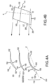
- FIG. 4A illustrates planar section 90 of airfoil 80 at outer diameter edge 108, midspan portion 114 and inner diameter edge 110.
- FIG. 4A illustrates two different geometric sweep positions of inner diameter edge 110 of airfoil 80.
- the embodiment illustrated by inner diameter edge 202 illustrates an aft or rearward sweep of approximately 28 degrees while the embodiment illustrated by inner diameter edge 200 illustrates an aft sweep of approximately 12 degrees.
- airfoil 80 can be moved along the chord line Z' towards the airflow (indicated by arrow 150) in order to increase sweep. Sweep can also be increased by positioning leading edge 100 farther upstream while leaving trailing edge 102 in the same position, increasing the chord of airfoil 80 as well as the geometric sweep.
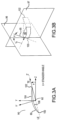
- FIG. 4B illustrates a meridional view of airfoil 80.
- Cross section 204 corresponds to inner diameter edge 200 with the increased sweep of 12 degrees.
- Cross section 206 corresponds to inner diameter edge 202 with an aerodynamic sweep of 28 degrees.
- the planar sections closer to inner diameter edge 110 can be moved forward (upstream) while leaving the portion between midspan portion 114 and outer diameter edge 108 alone.
- leading edge 100 can be extended forward (i.e., increased chord) while leaving the portion between midspan portion 114 and outer diameter edge 108 alone. Increasing the chord length reduces airfoil loading, thus reducing the likelihood of airfoil flow separation under high incidence conditions.
- an increased chord is illustrated near inner diameter edge 110 of fan exit stator 70. By increasing the chord, loading is reduced.
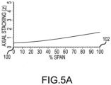
- FIG. 5A illustrates axial stacking of airfoil 80 across the span of airfoil 80.
- the axis labeled "% span" represents the spanwise distribution of airfoil 80.
- Zero percent (0%) represents inner diameter edge 110 of airfoil 80 and 100% represents outer diameter edge 108 of airfoil 80.
- FIG. 5A illustrates stacking along axis Z (illustrated in FIGs. 3A , 8A and 9A ).
- centroid 92 is disposed along axis Z in either the positive or negative direction.
- Each planar section 90 can be stacked based on the coordinate of its centroid 92.
- the graph illustrated in FIG. 5A illustrates the position of centroid 92 along the Z axis. As illustrated, the axial stacking of airfoil 80 increases throughout the span of airfoil 80.
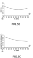
- FIG. 5B illustrates geometric sweep of airfoil 80 across the span of airfoil 80.
- Geometric sweep of airfoil 80 is illustrated by the positioning of centroid 92 along the Z' axis (parallel to the chord line of airfoil 80).
- the geometric sweep stacking almost doubles as the span increases from inner diameter edge 110 to outer diameter edge 108. This represents that leading edge 100 near inner diameter edge 110 is extended, increasing the chord of airfoil 80.
- Towards outer diameter edge 108 the chord becomes more constant, which is illustrated by the flatter representation of geometric sweep stacking in FIG. 5B .
- FIG. 5B illustrates tangential stacking, or bow, across the span of airfoil 80.
- Bow is illustrated by the positioning of centroid 92 along the Y axis.
- Bow represents stacking of airfoil in the tangential direction (Y).
- the bow of airfoil 80 is not symmetric about the 50% span line. Instead, the bow is decreasing from the inner diameter edge 110 to about the 60% span line. Here bow is weighted to be higher near inner diameter edge 110 and lower near outer diameter edge 108. Airfoil 80 thus would likely induce higher radial flow movement towards inner diameter edge 110 than outer diameter edge 108.
- FIG. 5C illustrates geometric dihedral across the span of airfoil 80. Dihedral is illustrated by the positioning of centroid 92 along the Y' axis. Dihedral represents lean of airfoil 80 in a direction normal to geometric sweep. As illustrated, the dihedral of airfoil 80 is decreasing throughout the span, starting slightly above the zero point and gradually decreasing.
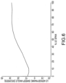
- FIG. 6 illustrates the aerodynamic sweep angle of airfoil 80.
- the aerodynamic sweep angle is determined based on stacking across the Z' axis illustrated in FIG. 5B relative to air flow stream surface 112. By increasing the chord at leading edge 100, as well as moving airfoil 80 planar sections forward in the sweep direction near inner diameter edge 110, the position of leading edge 100 of airfoil 80 is moved to create aft sweep. The forward positioning contributes to a higher aerodynamic sweep angle.
- the aerodynamic sweep angle of airfoil 80 is positive throughout the span of airfoil 80. Positive aerodynamic sweep redistributes flow towards inner edge 100.
- FIG. 7A illustrates the total chord length across the span of airfoil 80.
- the chord of airfoil 80 decreases from inner diameter edge 110 to outer diameter edge 108.
- the chord of airfoil 80 may be nearly 50% larger at inner diameter edge 110 than at outer diameter edge 108. This represents a significant increase in chord at inner diameter edge 110 as compared to outer diameter edge 108. It is shown how this change in total chord affects airfoil 80 on FIG. 8B .
- trailing edge 102 of airfoil 80 does not necessarily mirror the forward positional shift of leading edge 100 from inner diameter edge 110 to outer diameter edge 108.
- FIG. 7B illustrates total camber of airfoil 80 along its span.
- Camber represents the change in angle from leading edge 100 to trailing edge 102. As illustrated, the camber of airfoil 80 is greater than 50 degrees throughout the span.
- camber increases as the span approaches outer diameter edge 108. This can be seen in FIG. 4A .
- Outer diameter edge 108 has total turning from leading edge 100 to trailing edge 102 that is higher than the midspan portion 114 and inner diameter edge 110.
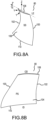
- FIG. 8A illustrates a perspective view of airfoil 80 from suction surface 106.
- FIG. 8A also includes the Y, Z, Y' and Z' axes for reference.
- the bow of airfoil 80 is not symmetric about the 50% span line. The bow is greater at inner diameter edge 110 than it is at outer diameter edge 108. This is shown by the curvature of airfoil 80 about suction surface 106 in the Y direction.
- Suction surface 106 is curved in the positive direction near inner diameter edge 110 for 20% span and near outer diameter edge 108 for 10% span. This illustrates the change in bow illustrated in FIG. 5B
- FIG. 8B illustrates a perspective view of airfoil 80 from pressure surface 104.
- FIG. 8B illustrates, in an axial projection, how leading edge 100 positioning for sweep affects airfoil 80.
- the position of leading edge 100 is substantially forward near inner diameter edge 110 for airfoil 80.
- the chord of airfoil 80 is greater at inner diameter edge 110 than at outer diameter edge 108. This represents the chord changes in FIG. 7A .
- This positioning of leading edge 100 contributes to an aerodynamic sweep that is positive throughout the span of airfoil 80.
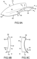
- FIG. 9A illustrates a perspective view of airfoil 80 from leading edge 100 and outer diameter edge 108.
- FIG. 9A also includes the Y, Z, Y' and Z' axis for reference. Suction surface 106 is illustrated. Again, the bow of airfoil 80 is illustrated by the curve of airfoil 80 from inner diameter edge 110 to outer diameter edge 108.
- FIG. 9B illustrates a front view of airfoil 80 from leading edge 100
- FIG. 9C illustrates a rear view of airfoil 80 from trailing edge 102.
- FIGs. 9B and 9C also illustrate the bow of airfoil 80.
- airfoil 80 reduces pressure loss through fan exit stator 70 relative to conventional systems. Often, highly loaded flow separates on an endwall adjacent inner diameter edge 110. By incorporating these features, flow is pulled towards inner diameter edge 110, reducing pressure loss and flow defect in the inner diameter edge region.
Landscapes
- Engineering & Computer Science (AREA)
- Mechanical Engineering (AREA)
- General Engineering & Computer Science (AREA)
- Physics & Mathematics (AREA)
- Fluid Mechanics (AREA)
- Geometry (AREA)
- Chemical & Material Sciences (AREA)
- Combustion & Propulsion (AREA)
- Structures Of Non-Positive Displacement Pumps (AREA)
Claims (10)
- Schaufelblatt (80) für einen Fan-Austrittsstator (70) eines Gasturbinentriebwerks, wobei das Schaufelblatt (80) Folgendes umfasst:eine Innendurchmesserkante (110, 200, 202) mit einer ersten Sehnenlänge;eine Außendurchmesserkante (108) mit einer zweiten Sehnenlänge, wobei die erste Sehnenlänge größer als die zweite Sehnenlänge ist;eine Hinterkante (102); gekennzeichnet durcheine Vorderkante (100) mit einer positiven aerodynamischen Pfeilung über im Wesentlichen die gesamte Spannweite der Vorderkante (100),wobei eine Sehne des Schaufelblatts (80) von der Innendurchmesserkante (110, 200, 202) zur Außendurchmesserkante (108) kontinuierlich abnimmt; undwobei eine Krümmung des Schaufelblatts (80) nicht symmetrisch um eine Mittelspannweite des Schaufelblatts (80) verläuft.
- Schaufelblatt nach Anspruch 1, wobei das Schaufelblatt einen Wölbungswinkel von mehr als 50 Grad über im Wesentlichen die gesamte Spannweite des Schaufelblatts aufweist.
- Schaufelblatt nach Anspruch 1 oder 2, wobei die Krümmung des Schaufelblatts an der Innendurchmesserkante (110, 200, 202) größer ist als an der Außendurchmesserkante (108).
- Schaufelblatt nach Anspruch 1, 2 oder 3, wobei ein V-Winkel des Schaufelblatts von der Innendurchmesserkante (110, 200, 202) zur Außendurchmesserkante (108) kontinuierlich abnimmt.
- Schaufelblatt nach einem der vorhergehenden Ansprüche, wobei die erste Sehnenlänge mindestens 20 Prozent größer ist als die zweite Sehnenlänge.
- Schaufelblatt nach Anspruch 5, wobei die erste Sehnenlänge mindestens 50 Prozent größer ist als die zweite Sehnenlänge.
- Schaufelblatt nach einem der vorhergehenden Ansprüche, ferner umfassend eine Saugfläche (106), die in der Nähe einer Endwand radial konkav zur Saugfläche (106) hin ist.
- Schaufelblatt nach Anspruch 7, wobei sich die Saugfläche (106) an der Innendurchmesserkante (110, 200, 202) weiter in tangentialer Richtung erstreckt als an der Außendurchmesserkante (108) .
- Schaufelblatt nach einem der vorhergehenden Ansprüche, wobei das Schaufelblatt eine Statorschaufel ist.
- Schaufelblatt nach Anspruch 9, wobei das Schaufelblatt einen Luftstrom direkt von einem Fan (42) empfängt.
Applications Claiming Priority (1)
| Application Number | Priority Date | Filing Date | Title |
|---|---|---|---|
| US201462050543P | 2014-09-15 | 2014-09-15 |
Publications (2)
| Publication Number | Publication Date |
|---|---|
| EP2995771A1 EP2995771A1 (de) | 2016-03-16 |
| EP2995771B1 true EP2995771B1 (de) | 2024-12-04 |
Family
ID=54062663
Family Applications (1)
| Application Number | Title | Priority Date | Filing Date |
|---|---|---|---|
| EP15183680.6A Active EP2995771B1 (de) | 2014-09-15 | 2015-09-03 | Turbofantriebwerk und stator |
Country Status (2)
| Country | Link |
|---|---|
| US (1) | US10060263B2 (de) |
| EP (1) | EP2995771B1 (de) |
Families Citing this family (30)
| Publication number | Priority date | Publication date | Assignee | Title |
|---|---|---|---|---|
| EP3108103B1 (de) | 2014-02-19 | 2023-09-27 | Raytheon Technologies Corporation | Fanschaufel für ein gastrubinentriebwerk |
| US10570916B2 (en) | 2014-02-19 | 2020-02-25 | United Technologies Corporation | Gas turbine engine airfoil |
| US9140127B2 (en) | 2014-02-19 | 2015-09-22 | United Technologies Corporation | Gas turbine engine airfoil |
| US10570915B2 (en) | 2014-02-19 | 2020-02-25 | United Technologies Corporation | Gas turbine engine airfoil |
| US10465702B2 (en) | 2014-02-19 | 2019-11-05 | United Technologies Corporation | Gas turbine engine airfoil |
| WO2015175052A2 (en) | 2014-02-19 | 2015-11-19 | United Technologies Corporation | Gas turbine engine airfoil |
| WO2015175044A2 (en) | 2014-02-19 | 2015-11-19 | United Technologies Corporation | Gas turbine engine airfoil |
| EP3108120B1 (de) | 2014-02-19 | 2021-03-31 | Raytheon Technologies Corporation | Gasturbinentriebwerk mit einer getriebearchitektur und einer spezifischen festen schaufelstruktur |
| WO2015126941A1 (en) | 2014-02-19 | 2015-08-27 | United Technologies Corporation | Gas turbine engine airfoil |
| WO2015175043A2 (en) | 2014-02-19 | 2015-11-19 | United Technologies Corporation | Gas turbine engine airfoil |
| EP3575551B1 (de) | 2014-02-19 | 2021-10-27 | Raytheon Technologies Corporation | Gasturbinenmotorschaufel |
| EP3985226B1 (de) | 2014-02-19 | 2024-12-25 | RTX Corporation | Gasturbinentriebwerk-schaufelprofil |
| WO2015175073A2 (en) | 2014-02-19 | 2015-11-19 | United Technologies Corporation | Gas turbine engine airfoil |
| EP3108123B1 (de) | 2014-02-19 | 2023-10-04 | Raytheon Technologies Corporation | Turboluftstrahltriebwerk mit getriebefan und niederdruckverdichterschaufeln |
| EP3108100B1 (de) | 2014-02-19 | 2021-04-14 | Raytheon Technologies Corporation | Gasturbinengebläseschaufel |
| EP3108106B1 (de) | 2014-02-19 | 2022-05-04 | Raytheon Technologies Corporation | Schaufelblatt eines gasturbinenmotors |
| EP3108105B1 (de) | 2014-02-19 | 2021-05-12 | Raytheon Technologies Corporation | Gasturbinenmotor-tragfläche |
| EP3108101B1 (de) | 2014-02-19 | 2022-04-20 | Raytheon Technologies Corporation | Gasturbinenmotor-tragfläche |
| WO2015126454A1 (en) | 2014-02-19 | 2015-08-27 | United Technologies Corporation | Gas turbine engine airfoil |
| US10584715B2 (en) | 2014-02-19 | 2020-03-10 | United Technologies Corporation | Gas turbine engine airfoil |
| US10495106B2 (en) | 2014-02-19 | 2019-12-03 | United Technologies Corporation | Gas turbine engine airfoil |
| EP3190269A1 (de) * | 2016-01-11 | 2017-07-12 | United Technologies Corporation | Schaufelreihe mit niedrigerenetischen nachlauf |
| FR3070448B1 (fr) * | 2017-08-28 | 2019-09-06 | Safran Aircraft Engines | Aube de redresseur de soufflante de turbomachine, ensemble de turbomachine comprenant une telle aube et turbomachine equipee de ladite aube ou dudit ensemble |
| US20190106989A1 (en) * | 2017-10-09 | 2019-04-11 | United Technologies Corporation | Gas turbine engine airfoil |
| EP3704386B1 (de) * | 2017-11-02 | 2024-01-17 | MTU Aero Engines AG | Generativ gefertigter zwischenkanal zur anordnung zwischen einem niederdruckverdichter und einem hochdruckverdichter, sowie entsprechendes fertigungsverfahren |
| US11396888B1 (en) | 2017-11-09 | 2022-07-26 | Williams International Co., L.L.C. | System and method for guiding compressible gas flowing through a duct |
| US10781705B2 (en) | 2018-11-27 | 2020-09-22 | Pratt & Whitney Canada Corp. | Inter-compressor flow divider profiling |
| US10920594B2 (en) * | 2018-12-12 | 2021-02-16 | Solar Turbines Incorporated | Modal response tuned turbine blade |
| GB202009933D0 (en) * | 2020-06-30 | 2020-08-12 | Rolls Royce Plc | Low speed fan tip camber |
| US12326114B2 (en) * | 2023-08-15 | 2025-06-10 | Rtx Corporation | Gas turbine engine with core debris protection |
Citations (2)
| Publication number | Priority date | Publication date | Assignee | Title |
|---|---|---|---|---|
| EP0887513A2 (de) * | 1997-06-27 | 1998-12-30 | General Electric Company | Turbinenschaufel |
| US20050008494A1 (en) * | 2003-03-28 | 2005-01-13 | Ishikawajima-Harima Heavy Industries Co., Ltd. | Aircraft engine, fan thereof and fan stator vane thereof |
Family Cites Families (18)
| Publication number | Priority date | Publication date | Assignee | Title |
|---|---|---|---|---|
| US5706647A (en) * | 1994-11-15 | 1998-01-13 | Solar Turbines Incorporated | Airfoil structure |
| US6195983B1 (en) * | 1999-02-12 | 2001-03-06 | General Electric Company | Leaned and swept fan outlet guide vanes |
| JP2002213202A (ja) * | 2001-01-12 | 2002-07-31 | Mitsubishi Heavy Ind Ltd | ガスタービン翼 |
| US6554564B1 (en) * | 2001-11-14 | 2003-04-29 | United Technologies Corporation | Reduced noise fan exit guide vane configuration for turbofan engines |
| US7547186B2 (en) * | 2004-09-28 | 2009-06-16 | Honeywell International Inc. | Nonlinearly stacked low noise turbofan stator |
| JP4911344B2 (ja) * | 2006-07-04 | 2012-04-04 | 株式会社Ihi | ターボファンエンジン |
| US7726937B2 (en) | 2006-09-12 | 2010-06-01 | United Technologies Corporation | Turbine engine compressor vanes |
| GB0622405D0 (en) * | 2006-11-10 | 2006-12-20 | Rolls Royce Plc | A turbine engine mounting arrangement |
| US8087884B2 (en) | 2006-11-30 | 2012-01-03 | General Electric Company | Advanced booster stator vane |
| US7967571B2 (en) * | 2006-11-30 | 2011-06-28 | General Electric Company | Advanced booster rotor blade |
| GB0704426D0 (en) * | 2007-03-08 | 2007-04-18 | Rolls Royce Plc | Aerofoil members for a turbomachine |
| US8167567B2 (en) | 2008-12-17 | 2012-05-01 | United Technologies Corporation | Gas turbine engine airfoil |
| US8105037B2 (en) * | 2009-04-06 | 2012-01-31 | United Technologies Corporation | Endwall with leading-edge hump |
| US9291059B2 (en) * | 2009-12-23 | 2016-03-22 | Alstom Technology Ltd. | Airfoil for a compressor blade |
| JP5603800B2 (ja) * | 2011-02-22 | 2014-10-08 | 株式会社日立製作所 | タービン静翼、およびそれを用いた蒸気タービン設備 |
| US8702398B2 (en) * | 2011-03-25 | 2014-04-22 | General Electric Company | High camber compressor rotor blade |
| US9074483B2 (en) * | 2011-03-25 | 2015-07-07 | General Electric Company | High camber stator vane |
| US9085985B2 (en) * | 2012-03-23 | 2015-07-21 | General Electric Company | Scalloped surface turbine stage |
-
2015
- 2015-08-14 US US14/827,059 patent/US10060263B2/en active Active
- 2015-09-03 EP EP15183680.6A patent/EP2995771B1/de active Active
Patent Citations (2)
| Publication number | Priority date | Publication date | Assignee | Title |
|---|---|---|---|---|
| EP0887513A2 (de) * | 1997-06-27 | 1998-12-30 | General Electric Company | Turbinenschaufel |
| US20050008494A1 (en) * | 2003-03-28 | 2005-01-13 | Ishikawajima-Harima Heavy Industries Co., Ltd. | Aircraft engine, fan thereof and fan stator vane thereof |
Also Published As
| Publication number | Publication date |
|---|---|
| US20160076380A1 (en) | 2016-03-17 |
| EP2995771A1 (de) | 2016-03-16 |
| US10060263B2 (en) | 2018-08-28 |
Similar Documents
| Publication | Publication Date | Title |
|---|---|---|
| EP2995771B1 (de) | Turbofantriebwerk und stator | |
| US11193496B2 (en) | Gas turbine engine airfoil | |
| US11209013B2 (en) | Gas turbine engine airfoil | |
| US11041507B2 (en) | Gas turbine engine airfoil | |
| EP3108116B1 (de) | Gasturbinenmotor | |
| US10794192B2 (en) | Gas turbine engine airfoil | |
| US20170167266A1 (en) | Gas turbine engine airfoil | |
| US9951633B2 (en) | Reduced length transition ducts | |
| US9163517B2 (en) | Gas turbine engine airfoil | |
| US10914315B2 (en) | Gas turbine engine airfoil | |
| EP3108101B1 (de) | Gasturbinenmotor-tragfläche | |
| US11193497B2 (en) | Gas turbine engine airfoil | |
| US20170175760A1 (en) | Gas turbine engine airfoil | |
| US20150233250A1 (en) | Gas turbine engine airfoil | |
| US10557477B2 (en) | Gas turbine engine airfoil | |
| US10519971B2 (en) | Gas turbine engine airfoil | |
| US10495106B2 (en) | Gas turbine engine airfoil |
Legal Events
| Date | Code | Title | Description |
|---|---|---|---|
| PUAI | Public reference made under article 153(3) epc to a published international application that has entered the european phase |
Free format text: ORIGINAL CODE: 0009012 |
|
| AK | Designated contracting states |
Kind code of ref document: A1 Designated state(s): AL AT BE BG CH CY CZ DE DK EE ES FI FR GB GR HR HU IE IS IT LI LT LU LV MC MK MT NL NO PL PT RO RS SE SI SK SM TR |
|
| AX | Request for extension of the european patent |
Extension state: BA ME |
|
| 17P | Request for examination filed |
Effective date: 20160916 |
|
| RAP1 | Party data changed (applicant data changed or rights of an application transferred) |
Owner name: UNITED TECHNOLOGIES CORPORATION |
|
| RBV | Designated contracting states (corrected) |
Designated state(s): AL AT BE BG CH CY CZ DE DK EE ES FI FR GB GR HR HU IE IS IT LI LT LU LV MC MK MT NL NO PL PT RO RS SE SI SK SM TR |
|
| STAA | Information on the status of an ep patent application or granted ep patent |
Free format text: STATUS: EXAMINATION IS IN PROGRESS |
|
| 17Q | First examination report despatched |
Effective date: 20200519 |
|
| RAP1 | Party data changed (applicant data changed or rights of an application transferred) |
Owner name: RAYTHEON TECHNOLOGIES CORPORATION |
|
| RAP3 | Party data changed (applicant data changed or rights of an application transferred) |
Owner name: RTX CORPORATION |
|
| GRAP | Despatch of communication of intention to grant a patent |
Free format text: ORIGINAL CODE: EPIDOSNIGR1 |
|
| STAA | Information on the status of an ep patent application or granted ep patent |
Free format text: STATUS: GRANT OF PATENT IS INTENDED |
|
| INTG | Intention to grant announced |
Effective date: 20240626 |
|
| GRAS | Grant fee paid |
Free format text: ORIGINAL CODE: EPIDOSNIGR3 |
|
| GRAA | (expected) grant |
Free format text: ORIGINAL CODE: 0009210 |
|
| STAA | Information on the status of an ep patent application or granted ep patent |
Free format text: STATUS: THE PATENT HAS BEEN GRANTED |
|
| AK | Designated contracting states |
Kind code of ref document: B1 Designated state(s): AL AT BE BG CH CY CZ DE DK EE ES FI FR GB GR HR HU IE IS IT LI LT LU LV MC MK MT NL NO PL PT RO RS SE SI SK SM TR |
|
| REG | Reference to a national code |
Ref country code: GB Ref legal event code: FG4D |
|
| REG | Reference to a national code |
Ref country code: CH Ref legal event code: EP |
|
| REG | Reference to a national code |
Ref country code: DE Ref legal event code: R096 Ref document number: 602015090556 Country of ref document: DE |
|
| REG | Reference to a national code |
Ref country code: IE Ref legal event code: FG4D |
|
| REG | Reference to a national code |
Ref country code: LT Ref legal event code: MG9D |
|
| REG | Reference to a national code |
Ref country code: NL Ref legal event code: MP Effective date: 20241204 |
|
| PG25 | Lapsed in a contracting state [announced via postgrant information from national office to epo] |
Ref country code: HR Free format text: LAPSE BECAUSE OF FAILURE TO SUBMIT A TRANSLATION OF THE DESCRIPTION OR TO PAY THE FEE WITHIN THE PRESCRIBED TIME-LIMIT Effective date: 20241204 |
|
| PG25 | Lapsed in a contracting state [announced via postgrant information from national office to epo] |
Ref country code: FI Free format text: LAPSE BECAUSE OF FAILURE TO SUBMIT A TRANSLATION OF THE DESCRIPTION OR TO PAY THE FEE WITHIN THE PRESCRIBED TIME-LIMIT Effective date: 20241204 |
|
| PG25 | Lapsed in a contracting state [announced via postgrant information from national office to epo] |
Ref country code: BG Free format text: LAPSE BECAUSE OF FAILURE TO SUBMIT A TRANSLATION OF THE DESCRIPTION OR TO PAY THE FEE WITHIN THE PRESCRIBED TIME-LIMIT Effective date: 20241204 |
|
| PG25 | Lapsed in a contracting state [announced via postgrant information from national office to epo] |
Ref country code: ES Free format text: LAPSE BECAUSE OF FAILURE TO SUBMIT A TRANSLATION OF THE DESCRIPTION OR TO PAY THE FEE WITHIN THE PRESCRIBED TIME-LIMIT Effective date: 20241204 |
|
| PG25 | Lapsed in a contracting state [announced via postgrant information from national office to epo] |
Ref country code: NO Free format text: LAPSE BECAUSE OF FAILURE TO SUBMIT A TRANSLATION OF THE DESCRIPTION OR TO PAY THE FEE WITHIN THE PRESCRIBED TIME-LIMIT Effective date: 20250304 |
|
| PG25 | Lapsed in a contracting state [announced via postgrant information from national office to epo] |
Ref country code: LV Free format text: LAPSE BECAUSE OF FAILURE TO SUBMIT A TRANSLATION OF THE DESCRIPTION OR TO PAY THE FEE WITHIN THE PRESCRIBED TIME-LIMIT Effective date: 20241204 Ref country code: GR Free format text: LAPSE BECAUSE OF FAILURE TO SUBMIT A TRANSLATION OF THE DESCRIPTION OR TO PAY THE FEE WITHIN THE PRESCRIBED TIME-LIMIT Effective date: 20250305 |
|
| PG25 | Lapsed in a contracting state [announced via postgrant information from national office to epo] |
Ref country code: RS Free format text: LAPSE BECAUSE OF FAILURE TO SUBMIT A TRANSLATION OF THE DESCRIPTION OR TO PAY THE FEE WITHIN THE PRESCRIBED TIME-LIMIT Effective date: 20250304 |
|
| PG25 | Lapsed in a contracting state [announced via postgrant information from national office to epo] |
Ref country code: NL Free format text: LAPSE BECAUSE OF FAILURE TO SUBMIT A TRANSLATION OF THE DESCRIPTION OR TO PAY THE FEE WITHIN THE PRESCRIBED TIME-LIMIT Effective date: 20241204 |
|
| REG | Reference to a national code |
Ref country code: AT Ref legal event code: MK05 Ref document number: 1748367 Country of ref document: AT Kind code of ref document: T Effective date: 20241204 |
|
| PG25 | Lapsed in a contracting state [announced via postgrant information from national office to epo] |
Ref country code: SM Free format text: LAPSE BECAUSE OF FAILURE TO SUBMIT A TRANSLATION OF THE DESCRIPTION OR TO PAY THE FEE WITHIN THE PRESCRIBED TIME-LIMIT Effective date: 20241204 |
|
| PG25 | Lapsed in a contracting state [announced via postgrant information from national office to epo] |
Ref country code: PL Free format text: LAPSE BECAUSE OF FAILURE TO SUBMIT A TRANSLATION OF THE DESCRIPTION OR TO PAY THE FEE WITHIN THE PRESCRIBED TIME-LIMIT Effective date: 20241204 |
|
| PG25 | Lapsed in a contracting state [announced via postgrant information from national office to epo] |
Ref country code: IS Free format text: LAPSE BECAUSE OF FAILURE TO SUBMIT A TRANSLATION OF THE DESCRIPTION OR TO PAY THE FEE WITHIN THE PRESCRIBED TIME-LIMIT Effective date: 20250404 |
|
| PG25 | Lapsed in a contracting state [announced via postgrant information from national office to epo] |
Ref country code: PT Free format text: LAPSE BECAUSE OF FAILURE TO SUBMIT A TRANSLATION OF THE DESCRIPTION OR TO PAY THE FEE WITHIN THE PRESCRIBED TIME-LIMIT Effective date: 20250404 |
|
| PG25 | Lapsed in a contracting state [announced via postgrant information from national office to epo] |
Ref country code: EE Free format text: LAPSE BECAUSE OF FAILURE TO SUBMIT A TRANSLATION OF THE DESCRIPTION OR TO PAY THE FEE WITHIN THE PRESCRIBED TIME-LIMIT Effective date: 20241204 |
|
| PG25 | Lapsed in a contracting state [announced via postgrant information from national office to epo] |
Ref country code: AT Free format text: LAPSE BECAUSE OF FAILURE TO SUBMIT A TRANSLATION OF THE DESCRIPTION OR TO PAY THE FEE WITHIN THE PRESCRIBED TIME-LIMIT Effective date: 20241204 Ref country code: RO Free format text: LAPSE BECAUSE OF FAILURE TO SUBMIT A TRANSLATION OF THE DESCRIPTION OR TO PAY THE FEE WITHIN THE PRESCRIBED TIME-LIMIT Effective date: 20241204 |
|
| PG25 | Lapsed in a contracting state [announced via postgrant information from national office to epo] |
Ref country code: SK Free format text: LAPSE BECAUSE OF FAILURE TO SUBMIT A TRANSLATION OF THE DESCRIPTION OR TO PAY THE FEE WITHIN THE PRESCRIBED TIME-LIMIT Effective date: 20241204 |
|
| PG25 | Lapsed in a contracting state [announced via postgrant information from national office to epo] |
Ref country code: CZ Free format text: LAPSE BECAUSE OF FAILURE TO SUBMIT A TRANSLATION OF THE DESCRIPTION OR TO PAY THE FEE WITHIN THE PRESCRIBED TIME-LIMIT Effective date: 20241204 |
|
| PG25 | Lapsed in a contracting state [announced via postgrant information from national office to epo] |
Ref country code: IT Free format text: LAPSE BECAUSE OF FAILURE TO SUBMIT A TRANSLATION OF THE DESCRIPTION OR TO PAY THE FEE WITHIN THE PRESCRIBED TIME-LIMIT Effective date: 20241204 |
|
| REG | Reference to a national code |
Ref country code: DE Ref legal event code: R097 Ref document number: 602015090556 Country of ref document: DE |
|
| PG25 | Lapsed in a contracting state [announced via postgrant information from national office to epo] |
Ref country code: SE Free format text: LAPSE BECAUSE OF FAILURE TO SUBMIT A TRANSLATION OF THE DESCRIPTION OR TO PAY THE FEE WITHIN THE PRESCRIBED TIME-LIMIT Effective date: 20241204 |
|
| PG25 | Lapsed in a contracting state [announced via postgrant information from national office to epo] |
Ref country code: DK Free format text: LAPSE BECAUSE OF FAILURE TO SUBMIT A TRANSLATION OF THE DESCRIPTION OR TO PAY THE FEE WITHIN THE PRESCRIBED TIME-LIMIT Effective date: 20241204 |
|
| PGFP | Annual fee paid to national office [announced via postgrant information from national office to epo] |
Ref country code: DE Payment date: 20250820 Year of fee payment: 11 |
|
| PLBE | No opposition filed within time limit |
Free format text: ORIGINAL CODE: 0009261 |
|
| STAA | Information on the status of an ep patent application or granted ep patent |
Free format text: STATUS: NO OPPOSITION FILED WITHIN TIME LIMIT |
|
| PGFP | Annual fee paid to national office [announced via postgrant information from national office to epo] |
Ref country code: GB Payment date: 20250820 Year of fee payment: 11 |
|
| PGFP | Annual fee paid to national office [announced via postgrant information from national office to epo] |
Ref country code: FR Payment date: 20250821 Year of fee payment: 11 |
|
| 26N | No opposition filed |
Effective date: 20250905 |