EP2995777B1 - Anneau d'aube pour moteur à turbine à gaz - Google Patents
Anneau d'aube pour moteur à turbine à gaz Download PDFInfo
- Publication number
- EP2995777B1 EP2995777B1 EP15184339.8A EP15184339A EP2995777B1 EP 2995777 B1 EP2995777 B1 EP 2995777B1 EP 15184339 A EP15184339 A EP 15184339A EP 2995777 B1 EP2995777 B1 EP 2995777B1
- Authority
- EP
- European Patent Office
- Prior art keywords
- attachment face
- vane
- airfoil
- side tangential
- suction side
- Prior art date
- Legal status (The legal status is an assumption and is not a legal conclusion. Google has not performed a legal analysis and makes no representation as to the accuracy of the status listed.)
- Active
Links
Images




Classifications
-
- F—MECHANICAL ENGINEERING; LIGHTING; HEATING; WEAPONS; BLASTING
- F01—MACHINES OR ENGINES IN GENERAL; ENGINE PLANTS IN GENERAL; STEAM ENGINES
- F01D—NON-POSITIVE DISPLACEMENT MACHINES OR ENGINES, e.g. STEAM TURBINES
- F01D9/00—Stators
- F01D9/02—Nozzles; Nozzle boxes; Stator blades; Guide conduits, e.g. individual nozzles
- F01D9/04—Nozzles; Nozzle boxes; Stator blades; Guide conduits, e.g. individual nozzles forming ring or sector
- F01D9/042—Nozzles; Nozzle boxes; Stator blades; Guide conduits, e.g. individual nozzles forming ring or sector fixing blades to stators
-
- F—MECHANICAL ENGINEERING; LIGHTING; HEATING; WEAPONS; BLASTING
- F01—MACHINES OR ENGINES IN GENERAL; ENGINE PLANTS IN GENERAL; STEAM ENGINES
- F01D—NON-POSITIVE DISPLACEMENT MACHINES OR ENGINES, e.g. STEAM TURBINES
- F01D25/00—Component parts, details, or accessories, not provided for in, or of interest apart from, other groups
- F01D25/24—Casings; Casing parts, e.g. diaphragms, casing fastenings
- F01D25/246—Fastening of diaphragms or stator-rings
-
- F—MECHANICAL ENGINEERING; LIGHTING; HEATING; WEAPONS; BLASTING
- F01—MACHINES OR ENGINES IN GENERAL; ENGINE PLANTS IN GENERAL; STEAM ENGINES
- F01D—NON-POSITIVE DISPLACEMENT MACHINES OR ENGINES, e.g. STEAM TURBINES
- F01D9/00—Stators
- F01D9/02—Nozzles; Nozzle boxes; Stator blades; Guide conduits, e.g. individual nozzles
- F01D9/04—Nozzles; Nozzle boxes; Stator blades; Guide conduits, e.g. individual nozzles forming ring or sector
- F01D9/041—Nozzles; Nozzle boxes; Stator blades; Guide conduits, e.g. individual nozzles forming ring or sector using blades
-
- F—MECHANICAL ENGINEERING; LIGHTING; HEATING; WEAPONS; BLASTING
- F04—POSITIVE - DISPLACEMENT MACHINES FOR LIQUIDS; PUMPS FOR LIQUIDS OR ELASTIC FLUIDS
- F04D—NON-POSITIVE-DISPLACEMENT PUMPS
- F04D29/00—Details, component parts, or accessories
- F04D29/40—Casings; Connections of working fluid
- F04D29/52—Casings; Connections of working fluid for axial pumps
- F04D29/54—Fluid-guiding means, e.g. diffusers
- F04D29/541—Specially adapted for elastic fluid pumps
- F04D29/542—Bladed diffusers
-
- F—MECHANICAL ENGINEERING; LIGHTING; HEATING; WEAPONS; BLASTING
- F04—POSITIVE - DISPLACEMENT MACHINES FOR LIQUIDS; PUMPS FOR LIQUIDS OR ELASTIC FLUIDS
- F04D—NON-POSITIVE-DISPLACEMENT PUMPS
- F04D29/00—Details, component parts, or accessories
- F04D29/60—Mounting; Assembling; Disassembling
- F04D29/64—Mounting; Assembling; Disassembling of axial pumps
- F04D29/644—Mounting; Assembling; Disassembling of axial pumps especially adapted for elastic fluid pumps
-
- F—MECHANICAL ENGINEERING; LIGHTING; HEATING; WEAPONS; BLASTING
- F05—INDEXING SCHEMES RELATING TO ENGINES OR PUMPS IN VARIOUS SUBCLASSES OF CLASSES F01-F04
- F05D—INDEXING SCHEME FOR ASPECTS RELATING TO NON-POSITIVE-DISPLACEMENT MACHINES OR ENGINES, GAS-TURBINES OR JET-PROPULSION PLANTS
- F05D2230/00—Manufacture
- F05D2230/50—Building or constructing in particular ways
- F05D2230/51—Building or constructing in particular ways in a modular way, e.g. using several identical or complementary parts or features
-
- F—MECHANICAL ENGINEERING; LIGHTING; HEATING; WEAPONS; BLASTING
- F05—INDEXING SCHEMES RELATING TO ENGINES OR PUMPS IN VARIOUS SUBCLASSES OF CLASSES F01-F04
- F05D—INDEXING SCHEME FOR ASPECTS RELATING TO NON-POSITIVE-DISPLACEMENT MACHINES OR ENGINES, GAS-TURBINES OR JET-PROPULSION PLANTS
- F05D2260/00—Function
- F05D2260/30—Retaining components in desired mutual position
-
- Y—GENERAL TAGGING OF NEW TECHNOLOGICAL DEVELOPMENTS; GENERAL TAGGING OF CROSS-SECTIONAL TECHNOLOGIES SPANNING OVER SEVERAL SECTIONS OF THE IPC; TECHNICAL SUBJECTS COVERED BY FORMER USPC CROSS-REFERENCE ART COLLECTIONS [XRACs] AND DIGESTS
- Y02—TECHNOLOGIES OR APPLICATIONS FOR MITIGATION OR ADAPTATION AGAINST CLIMATE CHANGE
- Y02T—CLIMATE CHANGE MITIGATION TECHNOLOGIES RELATED TO TRANSPORTATION
- Y02T50/00—Aeronautics or air transport
- Y02T50/60—Efficient propulsion technologies, e.g. for aircraft
Definitions
- the present disclosure relates to airfoil components for a gas turbine engine, and more particularly, to attachment faces for a turbine stator which itself has an airfoil with endwall platforms and which is radially compressed between supporting structural details.
- Gas turbine engines such as those that power modern commercial and military aircraft, generally include a compressor to pressurize an airflow, a combustor to burn a hydrocarbon fuel in the presence of the pressurized air, and a turbine to extract energy from the resultant combustion gases.
- the compressor and turbine sections include rotatable blade and stationary vane arrays.
- the blades and vanes typically include low and high-pressure airfoils, vanes, vane rings, shrouds, and nozzle segments.
- the stationary vane arrays are typically assembled between outer and inner shrouds, or rings, in a variety of manners. Although the actual elements may vary in their configuration and construction, one similarity is that the vanes are typically constructed to allow for thermal expansion. The thermal expansion is typically accommodated through assembly of the vanes relatively loosely in the inner and outer shrouds. Although effective, such assembly may result in various stresses.
- WO 2006/100256 A1 discloses a prior art diaphragm and blades for turbomachinery.
- the structural support includes an interface for attachment to an engine case structure.
- the structural support is an arcuate segment.
- the structural support is a full ring.
- the lug extends transverse to the mateface of the vane endwall.
- the axial attachment face, the pressure side tangential attachment face, and the suction side tangential attachment face are generally perpendicular to the radial attachment face.
- the axial attachment face is generally perpendicular to the pressure side tangential attachment face and the suction side tangential attachment face.
- the suction side tangential attachment face and the axial attachment face are downstream of an aerodynamic center of a resultant aerodynamic load generated by the airfoil fairing shell such that the in plane loading to the reaction forces on these faces is compressive.
- the suction side tangential attachment face is parallel to the tangential attachment face.
- suction side tangential attachment face and the pressure side tangential attachment face are non-parallel to the inner vane endwall.
- suction side tangential attachment face and the pressure side tangential attachment face are non-parallel.
- the suction side tangential attachment face is generally perpendicular to a resultant aerodynamic load generated by the airfoil.
- the suction side tangential attachment face is aligned with respect to a resultant aerodynamic load generated by the airfoil.
- FIG 1 schematically illustrates a gas turbine engine 20.
- the gas turbine engine 20 is disclosed herein as a two-spool turbo fan that generally incorporates a fan section 22, a compressor section 24, a combustor section 26, and a turbine section 28.
- Alternative engine architectures 200 might include an augmentor section 12, an exhaust duct section 14, and a nozzle section 16 ( Figure 2 ) among other systems or features.
- the fan section 22 drives air along a bypass flowpath and into the compressor section 24 to drive core air along a core flowpath.
- the core air is compressed then communicated into the combustor section 26 for downstream expansion through the turbine section 28.
- turbofan Although depicted as a turbofan in the disclosed non-limiting embodiment, it should be appreciated that the concepts described herein are not limited, only to turbofans as the teachings may be applied to other types of turbine engine architectures such as turbojets, turboshafts, and three-spool (plus fan) turbofans.
- the engine 20 generally includes a low spool 30 and a high spool 32 mounted for rotation about an engine central longitudinal axis A relative to an engine case structure 36 via several bearing compartments 38.
- the low spool 30 generally includes an inner shaft 40 that interconnects a fan 42, a low pressure compressor (“LPC”) 44 and a low pressure turbine (“LPT”) 46.
- the inner shaft 40 drives the fan 42 directly or through a geared architecture 48 to drive the fan 42 at a lower speed than the low spool 30.
- An exemplary reduction transmission is an epicyclic transmission, namely a planetary or star gear system.
- the high spool 32 includes an outer shaft 50 that interconnects a high pressure compressor (“HPC”) 52 a and high pressure turbine (“HPT”) 54.
- a combustor 56 is arranged between the HPC 52 and the HPT 54. Core airflow is compressed by the LPC 44, then the HPC 52, mixed with the fuel and burned in the combustor 56, then expanded over the HPT 54 and the LPT 46 which rotationally drive the respective low spool 30 and high spool 32 in response to the expansion.
- a shroud assembly 60 mounted to the engine case structure 36 supports a Blade Outer Air Seal (BOAS) assembly 62 with a multiple of circumferentially distributed BOAS 64 proximate to a rotor assembly 66 (one schematically shown).
- BOAS Blade Outer Air Seal
- the shroud assembly 60 and the BOAS assembly 62 are axially disposed between a forward stationary vane ring 68 and an aft stationary vane ring 70.
- the rotor assembly 66 includes an array of blades 84 circumferentially disposed around a disk 86.
- Each blade 84 includes a root 88, a platform 90, and an airfoil 92.
- the blade roots 88 are received within a rim 94 of the disk 86 and the airfoils 92 extend radially outward such that a tip 96 of each airfoil 92 adjacent to the blade outer air seal (BOAS) assembly 62.
- the platform 90 separates a gas path side inclusive of the airfoil 92 and a non-gas path side inclusive of the root 88.
- each airfoil 72 extends between a respective inner vane endwall 76 and an outer vane endwall 80 to form an airfoil fairing shell 106.
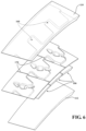
- Each airfoil fairing shell 106 is respectively clamped between an outer structural support 110, and an inner structural support 112 (also shown in Figure 5 ).
- the outer structural support 110, and the inner structural support 112 may be full rings or circumferentially segmented structures that are mounted within or a portion of the engine case structure 36, or attached thereto via fasteners, clamping, pins, or other such interface 114, 116 (illustrated schematically). That is, the airfoil fairing shells 106 are clamped into a full ring or circumferentially segmented outer and inner structural support 110, 112 that are, in turn, formed, fastened or otherwise located in the engine case structure 36 ( Figure 3 ). In the example circumferentially segmented structure, each segment of the outer structural support 110 and/or the inner structural support 112 may support a cluster of one or more airfoil fairing shells 106 (three shown in Figure 6 ).
- each airfoil 72 defines a blade chord between a leading edge 120, which may include various forward and/or aft sweep configurations, and a trailing edge 122.
- An aerodynamic center "C" of the airfoil is located at about a quarter chord position, however, such aerodynamic centers may vary dependent upon the airfoil.
- the inner vane endwall 76 and the outer vane endwall 80 are generally a parallelogram, chevron, arc, or other shape when viewed from the top and generally includes a respective forward edge 130, 132, an aft edge 134, 136 and a mateface 138A, 138B, 140A, 140B therebetween.
- the endwalls 70, 80 may be cylindrical, conical, arbitrary axisymmetric, or non-axisymmetric when viewed in cross-section.
- the non-gaspath face of the platform may be any of these as well. That is, the airfoil 72, the inner vane endwall 76, and the outer vane endwall 80 form the airfoil fairing shell 106 that is radially clamped by the outer structural support 110, and the inner structural support 112.
- the airfoil fairing shell 106 may include passages "P" (three shown) for cooling airflow and or electrical conduits, may be solid, may be hollow, or combinations thereof.
- passages "P" three shown
- Such an arrangement facilitates manufacture of metallic or non-metallic airfoil fairing shells, particularly but not exclusively those of low-ductility and/or low coefficient of thermal expansion materials, that are readily assembled to the outer structural support and the inner structural support which, in turn, are manufactured of metallic or non-metallic material and which may be manufactured from the same material as or dissimilar material to the airfoil fairing shells.
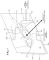
- the outer vane endwall 80 generally includes a radial attachment face 150, a suction side tangential attachment face 152, a pressure side tangential attachment face 154, and an axial attachment face 156.
- the attachment faces 150, 152, 154, 156 transmit axial and tangential aerodynamic loads from the airfoil fairing shell 106 into the structural supports and transmit clamping load through the fairing shell.
- the airfoil fairing shell 106 includes cylindrical, conical, arbitrary axisymmetric or planar radial attachment faces through which the spanwise clamping load is generally transmitted, and two pairs of orthogonal planar attachment faces through which aerodynamic loads and retention loads are generally transmitted, and which are quasi-orthogonal to the radial direction at the airfoil's circumferential station. It should be appreciated that one attachment face may be the primary attachment face while another attachment face is a secondary attachment face with respect configurations where the faces are rotated with respect to the engine axis. Axial and tangential oriented primary and secondary attachment faces are one disclosed non-limiting embodiment.
- primary and secondary attachment faces where axial and tangentially aligned are one specific type, where primary aligned with the resultant load is another specific type, and where primary aligned with the platform mateface edge is a third type.
- the primary and secondary are orthogonal to one another, and are quasi-orthogonal to the radial direction at the airfoil's circumferential station.
- the attachment faces 150, 152, 154, 156 are generally formed by thickened areas of the outer vane endwall 80 or other features such as tabs that are arranged to form these faces and interface with respective attachment faces formed by the associated outer structural support 110 ( Figure 6 ).
- the outer structural support 110 includes a series of lugs 160 provide tangential reaction faces that may be angled with respect to the engine axis A and extend transverse to a respective circumferential interface 170 between each airfoil fairing shell 106 ( Figure 6 , 9 , 10 ).
- the series of lugs 160 provide tangential reaction faces is parallel to the engine axis ( Figure 7 ).
- the attachment faces 150, 152, 154, 156 are arranged to transmit loads between the respective structural supports 110, 112 and the airfoil fairing shell 106.
- the surface of the thickened area of the airfoil fairing shell 106 forms the radial attachment face 150 that is clamped between the outer and inner structural support 110, 112.
- the attachment faces 152, 154, 156 react in-plane loads formed by the step transitions of the thickened areas of the outer vane endwall 80.
- the attachment faces 152, 154, 156 may be aligned with the axial and tangential directions or rotated to an arbitrary angle, such as that which presents a large face perpendicular to the resultant aerodynamic load ( Figure 9 ).
- the suction side tangential attachment face 152 is tasked with reacting aerodynamic in-plane loads and may be located downstream, and to the suction side of the aerodynamic center "C" of the airfoil such that aerodynamic loads tend to create compressive rather than tensile loads in the material that are in the plane with the platform between the aerodynamic center "C” to the attachment faces. That is, the suction side tangential attachment face 152 interfaces with one of the series of lugs 160 of the structural support 110 to provide a primary reaction load.
- the axial attachment face 156 also interfaces with the structural support 110 to provide a secondary reaction
- the primary reaction load and the secondary reaction load are non-parallel to the resultant aerodynamic load from the aerodynamic center "C" as generated by the airfoil 72, and the suction side tangential attachment face 152 is non-parallel to the matefaces 138A, 138B.
- the suction side tangential attachment face 152 and the pressure side tangential attachment face 154 are perpendicular to the forward edge 130 and the aft edge 134.
- a corner 180 at the interface between the suction side tangential attachment face 152 and the axial attachment face 156 is chamfered. The chamfered corner 180. The purpose of such a chamfer allows the load bearing faces on the stator shell to clear the edges of the complementary faces' fillet at their junction on the structural platform to prevent contact stress concentration ( Figure 11 ).
- the primary reaction load is parallel to a resultant aerodynamic load from an aerodynamic center as generated by the airfoil and the suction side tangential attachment face 152 is non-parallel to the matefaces 138A, 138B ( Figure 9 ).
- the primary and secondary load transmitting faces (alternatively called the axial and tangential faces when these faces are not angled with respect to the engine axis) are always perpendicular to each other, regardless of whether or not one of them is aligned to the resultant loading direction.
- suction side tangential attachment face 152 and the pressure side tangential attachment face 154 are generally parallel to the matefaces 138A, 138B of the outer vane endwall 80 ( Figure 10 ). Such arrangements may facilitate assembly into the engine 20.
- the attachment faces 150, 152, 154, 156 enable the use of separate structural platforms for a turbine stator which itself has an airfoil and endwalls while limiting tensile stresses in the plane of the platform.
Landscapes
- Engineering & Computer Science (AREA)
- Mechanical Engineering (AREA)
- General Engineering & Computer Science (AREA)
- Turbine Rotor Nozzle Sealing (AREA)
- Structures Of Non-Positive Displacement Pumps (AREA)
Claims (12)
- Anneau d'aube (68) pour moteur à turbine à gaz, comprenant :une pluralité de coquilles profilées (106) chacune présentant une section de profil aérodynamique (72) entre une paroi d'extrémité externe d'aube (80) et une paroi d'extrémité interne d'aube (76), au moins l'une desdites parois d'extrémité externe d'aube (80) et desdites parois d'extrémité interne d'aube (76) de chacune des coquilles profilées (106) de ladite pluralité forme une surface de jonction (138), chacune des coquilles profilées (106) de ladite pluralité étant adjacente à une autre coquille profilée (106) de ladite pluralité au niveau de ladite surface de jonction ; etun support structurel (110, 112),caractérisé en ce que :au moins l'une desdites parois d'extrémité externe d'aube (80) et desdites parois d'extrémité interne d'aube (76) de chacune des coquilles profilées (106) de ladite pluralité comprend une région épaissie présentant des transitions en marches, ladite région épaissie formant une surface de fixation radiale (150), une surface de fixation tangentielle côté succion (152), une surface de fixation tangentielle côté pression (154), et une surface de fixation axiale (156), ces surfaces étant configurées pour réagir aux charges dans le plan formées par lesdites transitions en marches ;ladite surface de fixation tangentielle côté succion (152) se trouvant en aval d'un centre aérodynamique (C) d'une charge aérodynamique résultante générée par ladite coquille profilée (106) de sorte que la charge dans le plan transmise aux forces de réaction sur ladite surface de fixation tangentielle côté succion (152) soit en compression ; etle support structurel (110, 112) comprend une pluralité de tenons (160), la surface de fixation tangentielle côté succion (152) de chacune des coquilles profilées (106) de ladite pluralité étant en interface avec l'un desdits tenons (160) afin de fournir une charge de réaction principale, et la surface de fixation axiale (156) de chacune des coquilles profilées (106) de ladite pluralité étant en interface avec le support structurel (110, 112) afin de fournir une charge de réaction secondaire.
- L'anneau d'aube (68) conformément à la revendication 1, selon laquelle ladite surface de fixation tangentielle côté succion (152) est parallèle à ladite surface de fixation tangentielle côté pression (154).
- L'anneau d'aube (68) conformément à la revendication 1 ou 2, selon laquelle ladite surface de fixation tangentielle côté succion (152) et ladite surface de fixation tangentielle côté pression (154) ne sont pas parallèles à ladite paroi d'extrémité interne d'aube (76), et/ou ne sont pas parallèles à un bord de ladite paroi d'extrémité externe d'aube (80).
- L'anneau d'aube (68) conformément à l'une quelconque des revendications 1 à 3, selon laquelle ladite surface de fixation tangentielle côté succion (152) est sensiblement perpendiculaire à une charge aérodynamique résultante générée par ladite coquille profilée (106).
- L'anneau d'aube (68) conformément à l'une quelconque des revendications 1 à 4, selon laquelle ladite surface de fixation tangentielle côté succion est alignée par rapport à une charge aérodynamique résultante générée par ladite coquille profilée (106).
- L'anneau d'aube (68) conformément à l'une quelconque des revendications précédentes, selon laquelle ledit support structurel (110) comprend une interface pour fixation à une structure de carter moteur.
- L'anneau d'aube (68) conformément à l'une quelconque des revendications précédentes, selon laquelle ledit support structurel (110) est un segment arqué.
- L'anneau d'aube (68) conformément à l'une quelconque des revendications 1 à 6, selon laquelle ledit support structurel (110) est un anneau complet.
- L'anneau d'aube (68) conformément à l'une quelconque des revendications précédentes, selon laquelle ledit tenon (160) se prolonge transversalement à ladite surface de jonction (138) de ladite paroi d'extrémité d'aube (80).
- L'anneau d'aube (68) conformément à l'une quelconque des revendications précédentes, selon laquelle ladite surface de fixation axiale (156), ladite surface de fixation tangentielle côté pression (194) et ladite surface de fixation tangentielle côté succion (152) sont sensiblement perpendiculaires à ladite surface de fixation radiale (150).
- L'anneau d'aube (68) conformément à la revendication 10, selon laquelle ladite surface de fixation axiale (156) est sensiblement perpendiculaire à ladite surface de fixation tangentielle côté pression (154) et à ladite surface de fixation tangentielle côté succion (152).
- L'anneau d'aube (68) conformément à l'une quelconque des revendications précédentes, selon laquelle ladite surface de fixation tangentielle côté succion (152) et ladite surface de fixation axiale (156) sont situées en aval d'un centre aérodynamique d'une charge aérodynamique résultante générée par ladite coquille profilée (106) de sorte que la charge dans le plan transmise aux forces de réaction sur ces surfaces soit en compression.
Applications Claiming Priority (1)
| Application Number | Priority Date | Filing Date | Title |
|---|---|---|---|
| US201462047710P | 2014-09-09 | 2014-09-09 |
Publications (2)
| Publication Number | Publication Date |
|---|---|
| EP2995777A1 EP2995777A1 (fr) | 2016-03-16 |
| EP2995777B1 true EP2995777B1 (fr) | 2025-05-21 |
Family
ID=54065825
Family Applications (1)
| Application Number | Title | Priority Date | Filing Date |
|---|---|---|---|
| EP15184339.8A Active EP2995777B1 (fr) | 2014-09-09 | 2015-09-08 | Anneau d'aube pour moteur à turbine à gaz |
Country Status (2)
| Country | Link |
|---|---|
| US (2) | US9816387B2 (fr) |
| EP (1) | EP2995777B1 (fr) |
Families Citing this family (23)
| Publication number | Priority date | Publication date | Assignee | Title |
|---|---|---|---|---|
| CA2372214A1 (fr) | 1999-04-30 | 2000-11-09 | Amylin Pharmaceuticals, Inc. | Exendines modifiees et agonistes de l'exendine |
| US7790681B2 (en) | 2002-12-17 | 2010-09-07 | Amylin Pharmaceuticals, Inc. | Treatment of cardiac arrhythmias with GLP-1 receptor ligands |
| NZ579621A (en) | 2004-02-11 | 2011-03-31 | Amylin Pharmaceuticals Inc | Hybrid polypeptides with selectable properties |
| CN101094689B (zh) | 2004-11-01 | 2013-06-12 | 安米林药品有限责任公司 | 治疗肥胖以及肥胖相关疾病和病症的方法 |
| WO2007022123A2 (fr) | 2005-08-11 | 2007-02-22 | Amylin Pharmaceuticals, Inc. | Polypeptides hybrides presentant des proprietes selectionnables |
| KR20070115947A (ko) | 2005-02-11 | 2007-12-06 | 아밀린 파마슈티칼스, 인크. | 선택가능한 특성들을 가지는 gip 유사체 및 하이브리드폴리펩타이드 |
| EP2330125A3 (fr) | 2005-08-11 | 2012-12-12 | Amylin Pharmaceuticals, Inc. | Polypeptides hybrides ayant des propriétés sélectionnables |
| PL1971362T3 (pl) | 2005-08-19 | 2015-05-29 | Amylin Pharmaceuticals Llc | Eksendyna do leczenia cukrzycy i zmniejszania masy ciała |
| EP2029160A2 (fr) | 2006-05-12 | 2009-03-04 | Amylin Pharmaceuticals, Inc. | Procédés permettant de rétablir l'équilibre glycémique |
| JP2009019027A (ja) | 2007-07-16 | 2009-01-29 | Hanmi Pharmaceutical Co Ltd | アミノ末端のアミノ酸が変異したインスリン分泌ペプチド誘導体 |
| EP2200626A4 (fr) | 2007-09-07 | 2012-02-15 | Ipsen Pharma Sas | Analogues d'exendine-4 et exendine-3 |
| US10072516B2 (en) * | 2014-09-24 | 2018-09-11 | United Technologies Corporation | Clamped vane arc segment having load-transmitting features |
| EP3034798B1 (fr) * | 2014-12-18 | 2018-03-07 | Ansaldo Energia Switzerland AG | Aube de turbine à gaz |
| USD777212S1 (en) * | 2015-06-20 | 2017-01-24 | General Electric Company | Nozzle ring |
| US11015613B2 (en) | 2017-01-12 | 2021-05-25 | General Electric Company | Aero loading shroud sealing |
| US10830074B2 (en) * | 2018-07-03 | 2020-11-10 | Raytheon Technologies Corporation | Potted stator vane with metal fillet |
| US10975706B2 (en) * | 2019-01-17 | 2021-04-13 | Raytheon Technologies Corporation | Frustic load transmission feature for composite structures |
| EP3805525A1 (fr) | 2019-10-09 | 2021-04-14 | Rolls-Royce plc | Ensemble aubes de turbine incorporant des matériaux composites à matrice céramique |
| US12359622B2 (en) * | 2020-04-09 | 2025-07-15 | Rtx Corporation | Vane support system |
| CN113000173B (zh) * | 2021-03-29 | 2022-08-05 | 南京工程学院 | 超硬纳米粉碎卧式液力双向对冲高速湍流磨 |
| US11732596B2 (en) | 2021-12-22 | 2023-08-22 | Rolls-Royce Plc | Ceramic matrix composite turbine vane assembly having minimalistic support spars |
| US12180859B2 (en) | 2023-02-01 | 2024-12-31 | Ge Infrastructure Technology Llc | Nozzle segment for use with multiple different turbine engines |
| US12535011B2 (en) | 2023-06-28 | 2026-01-27 | General Electric Company | High temperature gas turbine engine |
Citations (1)
| Publication number | Priority date | Publication date | Assignee | Title |
|---|---|---|---|---|
| US20140001285A1 (en) * | 2012-06-29 | 2014-01-02 | General Electric Company | Nozzle, a nozzle hanger, and a ceramic to metal attachment system |
Family Cites Families (38)
| Publication number | Priority date | Publication date | Assignee | Title |
|---|---|---|---|---|
| BE487115A (fr) | 1946-04-05 | |||
| US5788456A (en) * | 1997-02-21 | 1998-08-04 | Dresser-Rand Company | Turbine diaphragm assembly and method thereof |
| DE29715180U1 (de) | 1997-08-23 | 1997-10-16 | MTU Motoren- und Turbinen-Union München GmbH, 80995 München | Leitschaufel für eine Gasturbine |
| US6179560B1 (en) | 1998-12-16 | 2001-01-30 | United Technologies Corporation | Turbomachinery module with improved maintainability |
| US6343912B1 (en) | 1999-12-07 | 2002-02-05 | General Electric Company | Gas turbine or jet engine stator vane frame |
| US6220815B1 (en) | 1999-12-17 | 2001-04-24 | General Electric Company | Inter-stage seal retainer and assembly |
| US6347508B1 (en) | 2000-03-22 | 2002-02-19 | Allison Advanced Development Company | Combustor liner support and seal assembly |
| US6364606B1 (en) | 2000-11-08 | 2002-04-02 | Allison Advanced Development Company | High temperature capable flange |
| US6428272B1 (en) | 2000-12-22 | 2002-08-06 | General Electric Company | Bolted joint for rotor disks and method of reducing thermal gradients therein |
| US6422812B1 (en) | 2000-12-22 | 2002-07-23 | General Electric Company | Bolted joint for rotor disks and method of reducing thermal gradients therein |
| US6572331B1 (en) | 2001-12-28 | 2003-06-03 | General Electric Company | Supplemental seal for the chordal hinge seals in a gas turbine |
| US6595745B1 (en) | 2001-12-28 | 2003-07-22 | General Electric Company | Supplemental seal for the chordal hinge seals in a gas turbine |
| US7416362B2 (en) | 2002-08-16 | 2008-08-26 | Siemens Power Generation, Inc. | Multidirectionally compliant fastening system |
| US6969239B2 (en) | 2002-09-30 | 2005-11-29 | General Electric Company | Apparatus and method for damping vibrations between a compressor stator vane and a casing of a gas turbine engine |
| EP1573172B1 (fr) | 2002-12-19 | 2010-12-01 | Siemens Aktiengesellschaft | Turbine et procédé de démontage des aubes fixes d'une turbine |
| US7063505B2 (en) | 2003-02-07 | 2006-06-20 | General Electric Company | Gas turbine engine frame having struts connected to rings with morse pins |
| FR2860039B1 (fr) | 2003-09-19 | 2005-11-25 | Snecma Moteurs | Realisation de l'etancheite dans un turboreacteur pour le prelevement cabine par joints double sens a lamelles |
| DE60318852T2 (de) | 2003-10-03 | 2009-02-05 | General Electric Co. | Apparat und Methode zur Dämpfung von Vibrationen zwischen Kompressorleitschaufeln und dem Gehäuse einer Gasturbine |
| US7101150B2 (en) | 2004-05-11 | 2006-09-05 | Power Systems Mfg, Llc | Fastened vane assembly |
| US7300237B2 (en) | 2004-11-22 | 2007-11-27 | Inventio Ag | Self-locking bolted fastener |
| GB0505978D0 (en) | 2005-03-24 | 2005-04-27 | Alstom Technology Ltd | Interlocking turbine blades |
| US7329087B2 (en) | 2005-09-19 | 2008-02-12 | General Electric Company | Seal-less CMC vane to platform interfaces |
| US7926286B2 (en) | 2006-09-26 | 2011-04-19 | Pratt & Whitney Canada Corp. | Heat shield for a fuel manifold |
| FR2911933B1 (fr) | 2007-01-26 | 2009-05-01 | Snecma Sa | Dispositif d'assemblage de deux ensembles, par exemple pour stator de turbomachine |
| EP1965042A1 (fr) | 2007-03-02 | 2008-09-03 | Siemens Aktiengesellschaft | Dispositif de milieu et fixation de pièces statoriques |
| ES2365940T3 (es) | 2007-04-02 | 2011-10-13 | Ansaldo Energia S.P.A. | Un procedimiento de mantenimiento de una pluralidad de unidades de turbina de gas. |
| US7900461B2 (en) | 2007-05-31 | 2011-03-08 | Rolls-Royce Corporation | Combustor liner support and seal assembly |
| US8070427B2 (en) | 2007-10-31 | 2011-12-06 | General Electric Company | Gas turbines having flexible chordal hinge seals |
| FR2923530B1 (fr) | 2007-11-09 | 2014-04-04 | Snecma | Raccordement de bras radiaux a une virole circulaire par des axes et des entretoises |
| FR2931869B1 (fr) | 2008-05-29 | 2014-12-12 | Snecma | Bride annulaire de fixation d'un element de rotor ou de stator |
| EP2321499B1 (fr) | 2008-08-29 | 2017-12-13 | GKN Aerospace Sweden AB | Composant et moteur de type turbine a gaz comprenant le composant |
| US8167546B2 (en) * | 2009-09-01 | 2012-05-01 | United Technologies Corporation | Ceramic turbine shroud support |
| EP2473712B1 (fr) | 2009-09-02 | 2013-07-03 | Siemens Aktiengesellschaft | Appareil de montage |
| US8360716B2 (en) | 2010-03-23 | 2013-01-29 | United Technologies Corporation | Nozzle segment with reduced weight flange |
| FR2961250B1 (fr) | 2010-06-14 | 2012-07-20 | Snecma | Dispositif de refroidissement des alveoles d'un disque de rotor de turbomachine a l'aval du cone d'entrainement |
| US8753075B2 (en) | 2010-07-20 | 2014-06-17 | Rolls-Royce Corporation | Fan case assembly and method |
| US20120070302A1 (en) * | 2010-09-20 | 2012-03-22 | Ching-Pang Lee | Turbine airfoil vane with an impingement insert having a plurality of impingement nozzles |
| US9284889B2 (en) | 2011-11-16 | 2016-03-15 | United Technologies Corporation | Flexible seal system for a gas turbine engine |
-
2015
- 2015-09-01 US US14/841,943 patent/US9816387B2/en active Active
- 2015-09-08 EP EP15184339.8A patent/EP2995777B1/fr active Active
-
2017
- 2017-09-22 US US15/712,892 patent/US11041392B2/en active Active
Patent Citations (1)
| Publication number | Priority date | Publication date | Assignee | Title |
|---|---|---|---|---|
| US20140001285A1 (en) * | 2012-06-29 | 2014-01-02 | General Electric Company | Nozzle, a nozzle hanger, and a ceramic to metal attachment system |
Also Published As
| Publication number | Publication date |
|---|---|
| US20180010473A1 (en) | 2018-01-11 |
| US9816387B2 (en) | 2017-11-14 |
| EP2995777A1 (fr) | 2016-03-16 |
| US11041392B2 (en) | 2021-06-22 |
| US20160069201A1 (en) | 2016-03-10 |
Similar Documents
| Publication | Publication Date | Title |
|---|---|---|
| EP2995777B1 (fr) | Anneau d'aube pour moteur à turbine à gaz | |
| EP2937515B1 (fr) | Moteur à turbine à gaz doté d'une plateforme de pale de rotor contourée à surface non axisymétrique | |
| EP3594452B1 (fr) | Joint segmenté pour un moteur à turbine à gaz | |
| US10436070B2 (en) | Blade outer air seal having angled retention hook | |
| EP2998520B1 (fr) | Joint inter-étages pour moteur à turbine à gaz | |
| US9797262B2 (en) | Split damped outer shroud for gas turbine engine stator arrays | |
| EP2372102A2 (fr) | Plate-forme des pales de rotor d'une turbine à gaz | |
| EP3032033B2 (fr) | Ensemble de vanne pour moteur de turbine à gaz | |
| US9874101B2 (en) | Platform with curved edges | |
| EP3064711B1 (fr) | Composant pour un moteur à turbine à gaz, moteur à turbine à gaz et procédé de formation d'aube associés | |
| EP2930311B1 (fr) | Ensemble des aubes de stator pour une turbine à gaz | |
| EP2412926B1 (fr) | Aube creuse pour moteur à turbine à gaz | |
| EP2867471A2 (fr) | Profil d'aile portante pour aube de turbine de moteur à turbine à gaz | |
| NL2002312C2 (en) | Cooled turbine nozzle segment. | |
| US10689988B2 (en) | Disk lug impingement for gas turbine engine airfoil | |
| US9810088B2 (en) | Floating blade outer air seal assembly for gas turbine engine | |
| EP3869010B1 (fr) | Entretoise de fente de lame de rotor tangentielle pour un moteur à turbine à gaz |
Legal Events
| Date | Code | Title | Description |
|---|---|---|---|
| PUAI | Public reference made under article 153(3) epc to a published international application that has entered the european phase |
Free format text: ORIGINAL CODE: 0009012 |
|
| AK | Designated contracting states |
Kind code of ref document: A1 Designated state(s): AL AT BE BG CH CY CZ DE DK EE ES FI FR GB GR HR HU IE IS IT LI LT LU LV MC MK MT NL NO PL PT RO RS SE SI SK SM TR |
|
| AX | Request for extension of the european patent |
Extension state: BA ME |
|
| 17P | Request for examination filed |
Effective date: 20160916 |
|
| RAP1 | Party data changed (applicant data changed or rights of an application transferred) |
Owner name: UNITED TECHNOLOGIES CORPORATION |
|
| RBV | Designated contracting states (corrected) |
Designated state(s): AL AT BE BG CH CY CZ DE DK EE ES FI FR GB GR HR HU IE IS IT LI LT LU LV MC MK MT NL NO PL PT RO RS SE SI SK SM TR |
|
| STAA | Information on the status of an ep patent application or granted ep patent |
Free format text: STATUS: EXAMINATION IS IN PROGRESS |
|
| 17Q | First examination report despatched |
Effective date: 20190225 |
|
| RAP1 | Party data changed (applicant data changed or rights of an application transferred) |
Owner name: RAYTHEON TECHNOLOGIES CORPORATION |
|
| RAP3 | Party data changed (applicant data changed or rights of an application transferred) |
Owner name: RTX CORPORATION |
|
| GRAP | Despatch of communication of intention to grant a patent |
Free format text: ORIGINAL CODE: EPIDOSNIGR1 |
|
| STAA | Information on the status of an ep patent application or granted ep patent |
Free format text: STATUS: GRANT OF PATENT IS INTENDED |
|
| INTG | Intention to grant announced |
Effective date: 20241209 |
|
| RIN1 | Information on inventor provided before grant (corrected) |
Inventor name: DUBE, BRYAN P. Inventor name: CARR, JESSE M. |
|
| GRAS | Grant fee paid |
Free format text: ORIGINAL CODE: EPIDOSNIGR3 |
|
| GRAA | (expected) grant |
Free format text: ORIGINAL CODE: 0009210 |
|
| STAA | Information on the status of an ep patent application or granted ep patent |
Free format text: STATUS: THE PATENT HAS BEEN GRANTED |
|
| AK | Designated contracting states |
Kind code of ref document: B1 Designated state(s): AL AT BE BG CH CY CZ DE DK EE ES FI FR GB GR HR HU IE IS IT LI LT LU LV MC MK MT NL NO PL PT RO RS SE SI SK SM TR |
|
| REG | Reference to a national code |
Ref country code: GB Ref legal event code: FG4D |
|
| REG | Reference to a national code |
Ref country code: CH Ref legal event code: EP |
|
| REG | Reference to a national code |
Ref country code: DE Ref legal event code: R096 Ref document number: 602015091688 Country of ref document: DE |
|
| REG | Reference to a national code |
Ref country code: IE Ref legal event code: FG4D |
|
| REG | Reference to a national code |
Ref country code: NL Ref legal event code: MP Effective date: 20250521 |
|
| PG25 | Lapsed in a contracting state [announced via postgrant information from national office to epo] |
Ref country code: PT Free format text: LAPSE BECAUSE OF FAILURE TO SUBMIT A TRANSLATION OF THE DESCRIPTION OR TO PAY THE FEE WITHIN THE PRESCRIBED TIME-LIMIT Effective date: 20250922 Ref country code: ES Free format text: LAPSE BECAUSE OF FAILURE TO SUBMIT A TRANSLATION OF THE DESCRIPTION OR TO PAY THE FEE WITHIN THE PRESCRIBED TIME-LIMIT Effective date: 20250521 Ref country code: FI Free format text: LAPSE BECAUSE OF FAILURE TO SUBMIT A TRANSLATION OF THE DESCRIPTION OR TO PAY THE FEE WITHIN THE PRESCRIBED TIME-LIMIT Effective date: 20250521 |
|
| PGFP | Annual fee paid to national office [announced via postgrant information from national office to epo] |
Ref country code: DE Payment date: 20250820 Year of fee payment: 11 |
|
| REG | Reference to a national code |
Ref country code: LT Ref legal event code: MG9D |
|
| PG25 | Lapsed in a contracting state [announced via postgrant information from national office to epo] |
Ref country code: GR Free format text: LAPSE BECAUSE OF FAILURE TO SUBMIT A TRANSLATION OF THE DESCRIPTION OR TO PAY THE FEE WITHIN THE PRESCRIBED TIME-LIMIT Effective date: 20250822 Ref country code: NO Free format text: LAPSE BECAUSE OF FAILURE TO SUBMIT A TRANSLATION OF THE DESCRIPTION OR TO PAY THE FEE WITHIN THE PRESCRIBED TIME-LIMIT Effective date: 20250821 |
|
| PG25 | Lapsed in a contracting state [announced via postgrant information from national office to epo] |
Ref country code: PL Free format text: LAPSE BECAUSE OF FAILURE TO SUBMIT A TRANSLATION OF THE DESCRIPTION OR TO PAY THE FEE WITHIN THE PRESCRIBED TIME-LIMIT Effective date: 20250521 Ref country code: NL Free format text: LAPSE BECAUSE OF FAILURE TO SUBMIT A TRANSLATION OF THE DESCRIPTION OR TO PAY THE FEE WITHIN THE PRESCRIBED TIME-LIMIT Effective date: 20250521 |
|
| PG25 | Lapsed in a contracting state [announced via postgrant information from national office to epo] |
Ref country code: BG Free format text: LAPSE BECAUSE OF FAILURE TO SUBMIT A TRANSLATION OF THE DESCRIPTION OR TO PAY THE FEE WITHIN THE PRESCRIBED TIME-LIMIT Effective date: 20250521 |
|
| PGFP | Annual fee paid to national office [announced via postgrant information from national office to epo] |
Ref country code: GB Payment date: 20250822 Year of fee payment: 11 |
|
| PG25 | Lapsed in a contracting state [announced via postgrant information from national office to epo] |
Ref country code: HR Free format text: LAPSE BECAUSE OF FAILURE TO SUBMIT A TRANSLATION OF THE DESCRIPTION OR TO PAY THE FEE WITHIN THE PRESCRIBED TIME-LIMIT Effective date: 20250521 |
|
| PGFP | Annual fee paid to national office [announced via postgrant information from national office to epo] |
Ref country code: FR Payment date: 20250820 Year of fee payment: 11 |
|
| PG25 | Lapsed in a contracting state [announced via postgrant information from national office to epo] |
Ref country code: RS Free format text: LAPSE BECAUSE OF FAILURE TO SUBMIT A TRANSLATION OF THE DESCRIPTION OR TO PAY THE FEE WITHIN THE PRESCRIBED TIME-LIMIT Effective date: 20250821 |
|
| PG25 | Lapsed in a contracting state [announced via postgrant information from national office to epo] |
Ref country code: IS Free format text: LAPSE BECAUSE OF FAILURE TO SUBMIT A TRANSLATION OF THE DESCRIPTION OR TO PAY THE FEE WITHIN THE PRESCRIBED TIME-LIMIT Effective date: 20250921 |
|
| PG25 | Lapsed in a contracting state [announced via postgrant information from national office to epo] |
Ref country code: LV Free format text: LAPSE BECAUSE OF FAILURE TO SUBMIT A TRANSLATION OF THE DESCRIPTION OR TO PAY THE FEE WITHIN THE PRESCRIBED TIME-LIMIT Effective date: 20250521 |
|
| REG | Reference to a national code |
Ref country code: AT Ref legal event code: MK05 Ref document number: 1796912 Country of ref document: AT Kind code of ref document: T Effective date: 20250521 |
|
| PG25 | Lapsed in a contracting state [announced via postgrant information from national office to epo] |
Ref country code: DK Free format text: LAPSE BECAUSE OF FAILURE TO SUBMIT A TRANSLATION OF THE DESCRIPTION OR TO PAY THE FEE WITHIN THE PRESCRIBED TIME-LIMIT Effective date: 20250521 Ref country code: AT Free format text: LAPSE BECAUSE OF FAILURE TO SUBMIT A TRANSLATION OF THE DESCRIPTION OR TO PAY THE FEE WITHIN THE PRESCRIBED TIME-LIMIT Effective date: 20250521 Ref country code: SM Free format text: LAPSE BECAUSE OF FAILURE TO SUBMIT A TRANSLATION OF THE DESCRIPTION OR TO PAY THE FEE WITHIN THE PRESCRIBED TIME-LIMIT Effective date: 20250521 |
|
| PG25 | Lapsed in a contracting state [announced via postgrant information from national office to epo] |
Ref country code: CZ Free format text: LAPSE BECAUSE OF FAILURE TO SUBMIT A TRANSLATION OF THE DESCRIPTION OR TO PAY THE FEE WITHIN THE PRESCRIBED TIME-LIMIT Effective date: 20250521 |
|
| PG25 | Lapsed in a contracting state [announced via postgrant information from national office to epo] |
Ref country code: EE Free format text: LAPSE BECAUSE OF FAILURE TO SUBMIT A TRANSLATION OF THE DESCRIPTION OR TO PAY THE FEE WITHIN THE PRESCRIBED TIME-LIMIT Effective date: 20250521 |
|
| PG25 | Lapsed in a contracting state [announced via postgrant information from national office to epo] |
Ref country code: RO Free format text: LAPSE BECAUSE OF FAILURE TO SUBMIT A TRANSLATION OF THE DESCRIPTION OR TO PAY THE FEE WITHIN THE PRESCRIBED TIME-LIMIT Effective date: 20250521 Ref country code: SK Free format text: LAPSE BECAUSE OF FAILURE TO SUBMIT A TRANSLATION OF THE DESCRIPTION OR TO PAY THE FEE WITHIN THE PRESCRIBED TIME-LIMIT Effective date: 20250521 |
|
| PG25 | Lapsed in a contracting state [announced via postgrant information from national office to epo] |
Ref country code: IT Free format text: LAPSE BECAUSE OF FAILURE TO SUBMIT A TRANSLATION OF THE DESCRIPTION OR TO PAY THE FEE WITHIN THE PRESCRIBED TIME-LIMIT Effective date: 20250521 |
|
| REG | Reference to a national code |
Ref country code: DE Ref legal event code: R097 Ref document number: 602015091688 Country of ref document: DE |
|
| PLBE | No opposition filed within time limit |
Free format text: ORIGINAL CODE: 0009261 |
|
| STAA | Information on the status of an ep patent application or granted ep patent |
Free format text: STATUS: NO OPPOSITION FILED WITHIN TIME LIMIT |
|
| REG | Reference to a national code |
Ref country code: CH Ref legal event code: L10 Free format text: ST27 STATUS EVENT CODE: U-0-0-L10-L00 (AS PROVIDED BY THE NATIONAL OFFICE) Effective date: 20260402 |
|
| 26N | No opposition filed |
Effective date: 20260224 |