EP2995808B1 - Verfahren zur Bestimmung des Betriebspunktes einer hydraulischen Maschine und Anlage zur Umwandlung hydraulischer Energie - Google Patents
Verfahren zur Bestimmung des Betriebspunktes einer hydraulischen Maschine und Anlage zur Umwandlung hydraulischer Energie Download PDFInfo
- Publication number
- EP2995808B1 EP2995808B1 EP14290276.6A EP14290276A EP2995808B1 EP 2995808 B1 EP2995808 B1 EP 2995808B1 EP 14290276 A EP14290276 A EP 14290276A EP 2995808 B1 EP2995808 B1 EP 2995808B1
- Authority
- EP
- European Patent Office
- Prior art keywords
- machine
- real
- coordinates
- operating point
- turbine
- Prior art date
- Legal status (The legal status is an assumption and is not a legal conclusion. Google has not performed a legal analysis and makes no representation as to the accuracy of the status listed.)
- Active
Links
Images

Classifications
-
- F—MECHANICAL ENGINEERING; LIGHTING; HEATING; WEAPONS; BLASTING
- F03—MACHINES OR ENGINES FOR LIQUIDS; WIND, SPRING, OR WEIGHT MOTORS; PRODUCING MECHANICAL POWER OR A REACTIVE PROPULSIVE THRUST, NOT OTHERWISE PROVIDED FOR
- F03B—MACHINES OR ENGINES FOR LIQUIDS
- F03B15/00—Controlling
- F03B15/02—Controlling by varying liquid flow
- F03B15/04—Controlling by varying liquid flow of turbines
- F03B15/06—Regulating, i.e. acting automatically
-
- F—MECHANICAL ENGINEERING; LIGHTING; HEATING; WEAPONS; BLASTING
- F03—MACHINES OR ENGINES FOR LIQUIDS; WIND, SPRING, OR WEIGHT MOTORS; PRODUCING MECHANICAL POWER OR A REACTIVE PROPULSIVE THRUST, NOT OTHERWISE PROVIDED FOR
- F03B—MACHINES OR ENGINES FOR LIQUIDS
- F03B15/00—Controlling
- F03B15/02—Controlling by varying liquid flow
- F03B15/04—Controlling by varying liquid flow of turbines
- F03B15/06—Regulating, i.e. acting automatically
- F03B15/14—Regulating, i.e. acting automatically by or of water level
-
- F—MECHANICAL ENGINEERING; LIGHTING; HEATING; WEAPONS; BLASTING
- F03—MACHINES OR ENGINES FOR LIQUIDS; WIND, SPRING, OR WEIGHT MOTORS; PRODUCING MECHANICAL POWER OR A REACTIVE PROPULSIVE THRUST, NOT OTHERWISE PROVIDED FOR
- F03B—MACHINES OR ENGINES FOR LIQUIDS
- F03B3/00—Machines or engines of reaction type; Parts or details peculiar thereto
- F03B3/02—Machines or engines of reaction type; Parts or details peculiar thereto with radial flow at high-pressure side and axial flow at low-pressure side of rotors, e.g. Francis turbines
-
- F—MECHANICAL ENGINEERING; LIGHTING; HEATING; WEAPONS; BLASTING
- F03—MACHINES OR ENGINES FOR LIQUIDS; WIND, SPRING, OR WEIGHT MOTORS; PRODUCING MECHANICAL POWER OR A REACTIVE PROPULSIVE THRUST, NOT OTHERWISE PROVIDED FOR
- F03B—MACHINES OR ENGINES FOR LIQUIDS
- F03B3/00—Machines or engines of reaction type; Parts or details peculiar thereto
- F03B3/16—Stators
- F03B3/18—Stator blades; Guide conduits or vanes, e.g. adjustable
- F03B3/183—Adjustable vanes, e.g. wicket gates
-
- G—PHYSICS
- G01—MEASURING; TESTING
- G01B—MEASURING LENGTH, THICKNESS OR SIMILAR LINEAR DIMENSIONS; MEASURING ANGLES; MEASURING AREAS; MEASURING IRREGULARITIES OF SURFACES OR CONTOURS
- G01B21/00—Measuring arrangements or details thereof, where the measuring technique is not covered by the other groups of this subclass, unspecified or not relevant
-
- F—MECHANICAL ENGINEERING; LIGHTING; HEATING; WEAPONS; BLASTING
- F05—INDEXING SCHEMES RELATING TO ENGINES OR PUMPS IN VARIOUS SUBCLASSES OF CLASSES F01-F04
- F05B—INDEXING SCHEME RELATING TO WIND, SPRING, WEIGHT, INERTIA OR LIKE MOTORS, TO MACHINES OR ENGINES FOR LIQUIDS COVERED BY SUBCLASSES F03B, F03D AND F03G
- F05B2220/00—Application
- F05B2220/30—Application in turbines
- F05B2220/32—Application in turbines in water turbines
-
- F—MECHANICAL ENGINEERING; LIGHTING; HEATING; WEAPONS; BLASTING
- F05—INDEXING SCHEMES RELATING TO ENGINES OR PUMPS IN VARIOUS SUBCLASSES OF CLASSES F01-F04
- F05B—INDEXING SCHEME RELATING TO WIND, SPRING, WEIGHT, INERTIA OR LIKE MOTORS, TO MACHINES OR ENGINES FOR LIQUIDS COVERED BY SUBCLASSES F03B, F03D AND F03G
- F05B2260/00—Function
- F05B2260/80—Diagnostics
-
- F—MECHANICAL ENGINEERING; LIGHTING; HEATING; WEAPONS; BLASTING
- F05—INDEXING SCHEMES RELATING TO ENGINES OR PUMPS IN VARIOUS SUBCLASSES OF CLASSES F01-F04
- F05B—INDEXING SCHEME RELATING TO WIND, SPRING, WEIGHT, INERTIA OR LIKE MOTORS, TO MACHINES OR ENGINES FOR LIQUIDS COVERED BY SUBCLASSES F03B, F03D AND F03G
- F05B2260/00—Function
- F05B2260/84—Modelling or simulation
-
- F—MECHANICAL ENGINEERING; LIGHTING; HEATING; WEAPONS; BLASTING
- F05—INDEXING SCHEMES RELATING TO ENGINES OR PUMPS IN VARIOUS SUBCLASSES OF CLASSES F01-F04
- F05B—INDEXING SCHEME RELATING TO WIND, SPRING, WEIGHT, INERTIA OR LIKE MOTORS, TO MACHINES OR ENGINES FOR LIQUIDS COVERED BY SUBCLASSES F03B, F03D AND F03G
- F05B2270/00—Control
- F05B2270/10—Purpose of the control system
- F05B2270/20—Purpose of the control system to optimise the performance of a machine
-
- Y—GENERAL TAGGING OF NEW TECHNOLOGICAL DEVELOPMENTS; GENERAL TAGGING OF CROSS-SECTIONAL TECHNOLOGIES SPANNING OVER SEVERAL SECTIONS OF THE IPC; TECHNICAL SUBJECTS COVERED BY FORMER USPC CROSS-REFERENCE ART COLLECTIONS [XRACs] AND DIGESTS
- Y02—TECHNOLOGIES OR APPLICATIONS FOR MITIGATION OR ADAPTATION AGAINST CLIMATE CHANGE
- Y02E—REDUCTION OF GREENHOUSE GAS [GHG] EMISSIONS, RELATED TO ENERGY GENERATION, TRANSMISSION OR DISTRIBUTION
- Y02E10/00—Energy generation through renewable energy sources
- Y02E10/20—Hydro energy
Definitions
- the invention relates to a method for determining the operating point of a hydraulic machine that belongs to an installation for converting hydraulic energy into mechanical or electrical energy.
- the invention also concerns an installation for converting hydraulic energy into mechanical or electrical energy on which the method can be implemented.
- EP1 138 941 discloses a method to determine the net head by determining the current measurable operating point of a hydraulic machine, comparing it with a demand value and varying the net head fed into the turbine regulator until the actual and demand values agree.
- the invention intends to solve this drawback by proposing a method for determining the operating point of a hydraulic machine that is more reliable and that can be implemented under low waterfall conditions.
- the invention concerns a method as defined in claim 1.
- the invention it is possible to determine the net head and the flow rate of the hydraulic machine by finding its operating point.
- the operating point results from an algorithm calculation compiled by an electronic control unit, which means that the installation does not include any measurement device linked to the water flow. Therefore, net head and flow rate calculations are accurate for "clean” water, as well as for "dirty” water, that is water containing impurities, such as dust or sand.
- the invention also concerns an installation for converting hydraulic energy into mechanical or electrical energy as defined in claim 8.
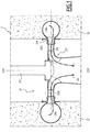
- Figure 1 represents an installation 2 for converting hydraulic energy into mechanical or electrical energy.
- the installation 2 includes a hydraulic machine.
- this hydraulic machine is a Francis turbine 20 that uses hydraulic energy to set a shaft 201 in rotation around an axis Z201.
- the shaft 201 is secured to a non-represented rotor of an alternator to produce electricity.
- the turbine 20 includes a volute 200 that is supported by concrete blocks 22 and 24.
- a non-represented penstock extends between a non-represented upstream reservoir and the volute 200. This penstock generates a forced water flow F to power the turbine 20.
- the turbine 20 includes a runner 202 that is surrounded by the volute 200 and that includes blades 208 between which water flows in operating conditions. As a result, the runner 202 rotates around an axis Z202 that is superimposed with the rotation axis Z201.
- a distributor is arranged around the runner 202. It includes a plurality of movable guide vanes 206 that are evenly distributed around the runner 202.
- a pre-distributor is disposed upstream of and around the distributor. The pre-distributor is formed by a plurality of fixed vanes 204 evenly distributed around the axis of rotation Z202 of the runner 202.
- a suction pipe 26 is disposed below the runner 202 and is adapted to evacuate water downstream.
- the guide vanes 206 of the distributor have each an adjustable pitch around an axis Z206 parallel to the axis of rotation Z202 of the runner 202. Consequently, they may be swiveled around axis Z206 to regulate the water flow rate.
- the guide vanes 206 are all oriented with the same angle relative to a closed position. In other words, they are synchronized.
- the guide vanes opening that is the degree of openness of the guide vanes relative to their closed position, is known as it is a parameter that is controlled.
- the hillchart of a turbine is a collection of operating points that are each defined by a quadruplet of values N11, T11, Q11, Y wherein Y is the opening of the guide vanes 206.
- Y the opening of the guide vanes 206.
- an "iso-opening" curve can be extracted from the hillchart.
- the triplets of values N'11, T'11, Q'11 refer to the whole collection of operating points of an iso-opening curve.
- the triplets of values N'11, T'11, Q'11 form a first series of potential operating points.
- Figure 2 shows an iso-opening curve example C1.
- the operating points are positioned only depending on their coordinate along N11 axis and on their coordinate along T11 axis.
- the iso-opening curve is plotted in dotted line.
- the series of potential operating points N'11, T'11, Q'11 is updated if, for any reason, the guide vanes opening changes.
- the operating point of turbine 20 is a point having for coordinates N11_real, T11_real, Q11_real.
- the upper right quadrant corresponds to turbine mode, wherein it is needed to determine the operating point of the machine.
- Turbine mode corresponds to the quadrant wherein N11 and T11 are both positive.
- T11 T D 5 ⁇ N 2 N 11 2
- the rotation speed N of the turbine 20 can be determined by measuring the frequency of the alternator coupled to the shaft 201.
- the second series includes the potential operating points of the turbine 20 at a certain rotation speed N of runner 202 and at a certain torque T exerted by water flow F on runner 202.
- N and torque T the operating point of turbine 20 is somewhere on the curve C2 joining the points of the second series.
- Two coordinates of the real operating point of the turbine 20 can then be deduced by determining the point that belongs both to the first and to the second series.
- This real operating point is located at the intersection between the iso-opening curve C1 and the curve C2.
- N11_real denotes the coordinate of the real operating point along N11 axis
- T11_real denotes the coordinate of the real operating point along T11 axis.
- the two coordinates N11_real and T11_real of the real operating point may be numerically interpolated.
- the real operating point is deduced in the considered operating range of the machine, that is in turbine mode in the example.
- net head calculation may be integrated in a loop control system aiming at stabilizing the net head of a hydraulic machine with S-characteristics. S-characteristics may be encountered during a pump-turbine start-up in turbine mode or with a Francis turbine under high water fall conditions.
- N11_real and T11_real allows determining the third coordinate Q11_real by mean of an interpolation of the hillchart.
- the flow rate Q of water flow F passing through the turbine 20 maybe then calculated on the basis of the equation 3.
- the calculation steps of the algorithm for determining the net head H and the flow rate Q are performed automatically by a non-represented electronic control unit that may be integrated in the turbine controller.
- Some partial derivative associated to the quadruplet N11_real, Q11_real, T11_real, Y of the real operating point can further be calculated.
- some partial derivative are ⁇ N 11 ⁇ Q 11 , Y ⁇ N 11 ⁇ T 11 , Q 11 ⁇ T 11 ⁇ Q 11
- a similar method can be implemented to determine the operating point of a double-regulated turbine, such as a Kaplan turbine or a Bulb turbine.
- a double-regulated turbine includes a hub equipped with movable blades. The flow rate of water circulating around the hub is also regulated thanks to a series of guide vanes.
- the first series of potential operating points N'11, T'11 is determined for the orientation affected to the movable blades of the double-regulated turbine and for the opening affected to guide vanes.
- the same calculation can be done to obtain the net head and the flow rate of water flowing through the double-regulated turbine.
- the rotation of the shaft 201 is used to power a mechanical device. Installation 2 then converts hydraulic energy into mechanical energy.
- the method can be implemented on a pump or a pump-turbine.
- the operating range in which is determined the operating point corresponds to the pump mode.
Landscapes
- Engineering & Computer Science (AREA)
- Chemical & Material Sciences (AREA)
- Combustion & Propulsion (AREA)
- Mechanical Engineering (AREA)
- General Engineering & Computer Science (AREA)
- Physics & Mathematics (AREA)
- General Physics & Mathematics (AREA)
- Hydraulic Turbines (AREA)
- Control Of Water Turbines (AREA)
Claims (11)
- Verfahren zum Bestimmen des Betriebspunkts einer Hydraulikmaschine (20) in einem betrachteten Betriebsbereich wie etwa einem Turbinenmodus, wobei das Verfahren dadurch gekennzeichnet ist, dass es Schritte umfasst, die aus dem Folgenden bestehen:a) Bestimmen von zwei Koordinaten (N'11, T'11) einer ersten Reihe von möglichen Betriebspunkten der Hydraulikmaschine (20) für eine auf Leitschaufeln (206) der Maschine angewendete Ausrichtung,b) Messen der Umdrehungsgeschwindigkeit (N) der Maschine,c) Bestimmen des Drehmoments (T), das durch einen Wasserfluss (F) auf die Maschine ausgeübt wird,d) Berechnen von zwei Koordinaten (N11, T11) einer zweiten Reihe von möglichen Betriebspunkten der Maschine in Abhängigkeit der bei Schritt b) gemessenen Umdrehungsgeschwindigkeit (N) und des bei Schritt c) bestimmten Drehmoments (T), unde) Ableiten von zwei Koordinaten (N11_wirklich, T11_wirklich) des Betriebspunkts, der in dem betrachteten Betriebsbereich der Maschine sowohl zu der ersten als auch zu der zweiten Reihe gehört.
- Verfahren nach Anspruch 1, dadurch gekennzeichnet, dass es einen Schritt f) nach dem Schritt e) umfasst, der aus dem Berechnen der auf die Hydraulikmaschine (20) ausgeübten Nettofallhöhe (H) auf Basis der beiden Koordinaten (N11_wirklich, T11_wirklich) des Betriebspunkts, die bei Schritt e) abgeleitet wurden, und der Umdrehungsgeschwindigkeit (N) oder des Drehmoments (T), die oder der bei Schritt b) oder c) abgeleitet wurde, besteht.
- Verfahren nach Anspruch 1 oder 2, dadurch gekennzeichnet, dass es einen Schritt g) nach dem Schritt e) umfasst, der aus dem Berechnen einer dritten Koordinate (Q11_wirklich) des Betriebspunkts der Maschine (20) auf der Basis der beiden Koordinaten (N11_wirklich, T11_wirklich) des Betriebspunkts, die bei Schritt e) abgeleitet wurden, besteht.
- Verfahren nach Anspruch 2 und 3, dadurch gekennzeichnet, dass es einen Schritt h) nach den Schritten f) und g) umfasst, der aus dem Berechnen der Durchflussmenge (Q) von Wasser, das durch die Maschine (20) verläuft, auf der Basis der bei Schritt f) berechneten Nettofallhöhe (H) und der bei Schritt g) berechneten dritten Koordinate (Q11_wirklich) des Betriebspunkts besteht.
- Verfahren nach Anspruch 3 oder 4, dadurch gekennzeichnet, dass es ferner einen Schritt umfasst, der aus dem Berechnen irgendeiner Teilableitung, die den Koordinaten (N11_wirklich, Q11_wirklich, T11_wirklich) des Maschinenbetriebspunkts zugehörig ist, besteht.
- Verfahren nach einem der vorhergehenden Ansprüche, dadurch gekennzeichnet, dass bei Schritt d) der wirkliche Betriebspunkt (N11_wirklich, T11_wirklich) durch Interpolation abgeleitet wird.
- Verfahren nach einem der vorhergehenden Ansprüche, dadurch gekennzeichnet, dass die Hydraulikmaschine eine doppelt regulierte Turbine ist, die eine mit beweglichen Schaufeln versehene Nabe umfasst, und dass bei Schritt a) die beiden Koordinaten (N'11, T'11) der ersten Reihe von möglichen Betriebspunkten auch für eine auf die beweglichen Schaufeln der Maschine angewendete Ausrichtung bestimmt werden.
- Einrichtung (2) zum Umwandeln von hydraulischer Energie in mechanische oder elektrische Energie, umfassend eine Hydraulikmaschine (20) und dadurch gekennzeichnet, dass sie ferner Folgendes umfasst:- Mittel zum Bestimmen von zwei Koordinaten (N'11, T'11) einer ersten Reihe von möglichen Betriebspunkten der Hydraulikmaschine (20) für eine auf Leitschaufeln (206) der Maschine angewendete Ausrichtung,- Mittel zum Messen der Umdrehungsgeschwindigkeit (N) der Maschine, und- Mittel zum Bestimmen des Drehmoments (T), das durch einen Wasserfluss (F) auf die Maschine ausgeübt wird,- Mittel zum Berechnen von zwei Koordinaten einer zweiten Reihe von möglichen Betriebspunkten (N11, T11) der Maschine in Abhängigkeit der bei Schritt b) gemessenen Umdrehungsgeschwindigkeit (N) und des bei Schritt c) bestimmten Drehmoments (T), und- Mittel zum Ableiten von zwei Koordinaten (N11_wirklich, T11_wirklich) des Betriebspunkts, der in einem betrachteten Betriebsbereich der Maschine wie etwa einem Turbinenmodus sowohl zu der ersten als auch zu der zweiten Reihe gehört.
- Einrichtung nach Anspruch 8, dadurch gekennzeichnet, dass die Hydraulikmaschine (20) eine Francis-Turbine ist.
- Einrichtung nach Anspruch 8, dadurch gekennzeichnet, dass die Hydraulikmaschine eine Pumpturbine ist.
- Einrichtung nach Anspruch 8, dadurch gekennzeichnet, dass die Hydraulikmaschine eine doppelt regulierte Turbine ist, die eine mit beweglichen Schaufeln versehene Nabe umfasst, und dass die Mittel zum Bestimmen der beiden Koordinaten (N'11, T'11) der ersten Reihe von Betriebspunkten auch eine auf die beweglichen Schaufeln der Maschine angewendete Ausrichtung berücksichtigen.
Priority Applications (8)
| Application Number | Priority Date | Filing Date | Title |
|---|---|---|---|
| PT142902766T PT2995808T (pt) | 2014-09-15 | 2014-09-15 | Método para determinar o ponto de funcionamento de uma máquina hidráulica e instalação para converter energia hidráulica |
| ES14290276.6T ES2627314T3 (es) | 2014-09-15 | 2014-09-15 | Procedimiento de determinación del punto de operación de una maquina hidráulica e instalación para la conversión de energía hidráulica |
| EP14290276.6A EP2995808B8 (de) | 2014-09-15 | 2014-09-15 | Verfahren zur Bestimmung des Betriebspunktes einer hydraulischen Maschine und Anlage zur Umwandlung hydraulischer Energie |
| US15/511,351 US10598145B2 (en) | 2014-09-15 | 2015-08-18 | Method for determining the operating point of a hydraulic machine and installation for converting hydraulic energy |
| KR1020177009777A KR102343779B1 (ko) | 2014-09-15 | 2015-08-18 | 수력 에너지를 변환하기 위한 수력학적 기계 및 시설의 작동점을 결정하기 위한 방법 |
| RU2017107718A RU2717468C2 (ru) | 2014-09-15 | 2015-08-18 | Способ определения рабочей точки гидравлической машины и установка для осуществления указанного способа |
| CN201580049434.3A CN106687684B (zh) | 2014-09-15 | 2015-08-18 | 确定液压机操作点的方法与转化液压能的装置 |
| PCT/EP2015/068927 WO2016041719A1 (en) | 2014-09-15 | 2015-08-18 | Method for determining the operating point of a hydraulic machine and installation for converting hydraulic energy |
Applications Claiming Priority (1)
| Application Number | Priority Date | Filing Date | Title |
|---|---|---|---|
| EP14290276.6A EP2995808B8 (de) | 2014-09-15 | 2014-09-15 | Verfahren zur Bestimmung des Betriebspunktes einer hydraulischen Maschine und Anlage zur Umwandlung hydraulischer Energie |
Publications (3)
| Publication Number | Publication Date |
|---|---|
| EP2995808A1 EP2995808A1 (de) | 2016-03-16 |
| EP2995808B1 true EP2995808B1 (de) | 2017-04-26 |
| EP2995808B8 EP2995808B8 (de) | 2017-08-09 |
Family
ID=51628079
Family Applications (1)
| Application Number | Title | Priority Date | Filing Date |
|---|---|---|---|
| EP14290276.6A Active EP2995808B8 (de) | 2014-09-15 | 2014-09-15 | Verfahren zur Bestimmung des Betriebspunktes einer hydraulischen Maschine und Anlage zur Umwandlung hydraulischer Energie |
Country Status (8)
| Country | Link |
|---|---|
| US (1) | US10598145B2 (de) |
| EP (1) | EP2995808B8 (de) |
| KR (1) | KR102343779B1 (de) |
| CN (1) | CN106687684B (de) |
| ES (1) | ES2627314T3 (de) |
| PT (1) | PT2995808T (de) |
| RU (1) | RU2717468C2 (de) |
| WO (1) | WO2016041719A1 (de) |
Families Citing this family (1)
| Publication number | Priority date | Publication date | Assignee | Title |
|---|---|---|---|---|
| EP3836335B1 (de) * | 2019-12-12 | 2025-06-25 | GE Renewable Technologies | Verfahren zum ankoppeln eines wasserkraftwerks an das netz mit mindestens zwei wasserkrafteinheiten |
Family Cites Families (11)
| Publication number | Priority date | Publication date | Assignee | Title |
|---|---|---|---|---|
| EP0303170B1 (de) * | 1987-08-14 | 1996-05-15 | Hitachi, Ltd. | Kontrollsystem für eine Hydrokraftanlage mit veränderlicher Geschwindigkeit |
| US5742515A (en) * | 1995-04-21 | 1998-04-21 | General Electric Co. | Asynchronous conversion method and apparatus for use with variable speed turbine hydroelectric generation |
| DE19719406C1 (de) * | 1997-05-12 | 1998-11-19 | Voith Hydro Gmbh & Co Kg | Verfahren zum Betreiben einer hydraulischen Maschine |
| DE19860617C1 (de) | 1998-12-29 | 2000-10-05 | Voith Hydro Gmbh & Co Kg | Verfahren zum Anfahren eines Maschinensatzes, umfassend eine Pumpturbine und einen Motorgenerator |
| AT4390U1 (de) * | 2000-03-31 | 2001-06-25 | Steiner Reinhard Dipl Ing | Verfahren zur ermittlung der nettofallhöhe von turbinen |
| JP4337270B2 (ja) | 2001-04-05 | 2009-09-30 | 株式会社日立製作所 | ポンプ水車 |
| JP2009221971A (ja) | 2008-03-17 | 2009-10-01 | Toshiba Corp | ポンプ水車 |
| JP5314441B2 (ja) | 2009-01-20 | 2013-10-16 | 日立三菱水力株式会社 | 遠心型水力機械 |
| IT1396927B1 (it) | 2009-11-13 | 2012-12-20 | Alfonsi | Turbina ad elevate prestazioni, particolarmente a potenza specifica incrementata. |
| DE102011115034A1 (de) * | 2011-10-07 | 2013-04-11 | Voith Patent Gmbh | Verfahren zur Primärregelung eines Wasserkraftwerks |
| JP5956885B2 (ja) | 2012-09-19 | 2016-07-27 | 株式会社東芝 | 水力機械およびその運転方法 |
-
2014
- 2014-09-15 EP EP14290276.6A patent/EP2995808B8/de active Active
- 2014-09-15 ES ES14290276.6T patent/ES2627314T3/es active Active
- 2014-09-15 PT PT142902766T patent/PT2995808T/pt unknown
-
2015
- 2015-08-18 WO PCT/EP2015/068927 patent/WO2016041719A1/en not_active Ceased
- 2015-08-18 RU RU2017107718A patent/RU2717468C2/ru active
- 2015-08-18 KR KR1020177009777A patent/KR102343779B1/ko active Active
- 2015-08-18 CN CN201580049434.3A patent/CN106687684B/zh active Active
- 2015-08-18 US US15/511,351 patent/US10598145B2/en active Active
Non-Patent Citations (1)
| Title |
|---|
| None * |
Also Published As
| Publication number | Publication date |
|---|---|
| RU2017107718A3 (de) | 2019-01-25 |
| CN106687684A (zh) | 2017-05-17 |
| RU2717468C2 (ru) | 2020-03-23 |
| US10598145B2 (en) | 2020-03-24 |
| EP2995808A1 (de) | 2016-03-16 |
| CN106687684B (zh) | 2019-06-04 |
| KR102343779B1 (ko) | 2021-12-24 |
| KR20170055517A (ko) | 2017-05-19 |
| EP2995808B8 (de) | 2017-08-09 |
| RU2017107718A (ru) | 2018-10-17 |
| US20170254313A1 (en) | 2017-09-07 |
| WO2016041719A1 (en) | 2016-03-24 |
| ES2627314T3 (es) | 2017-07-27 |
| PT2995808T (pt) | 2017-06-22 |
Similar Documents
| Publication | Publication Date | Title |
|---|---|---|
| JP5033033B2 (ja) | 水平軸風車の乱流強度計測方法 | |
| CN100385111C (zh) | 叶片螺距角度控制装置及风力发电装置 | |
| US20130302161A1 (en) | Controller of wind turbine and wind turbine | |
| Paderi et al. | Experimental investigation in a Wells turbine under bi-directional flow | |
| Meyer et al. | Instantaneous flow field measurements in the interstage section between a fan and the outlet guiding vanes at different axial positions | |
| JP6309911B2 (ja) | 疲労評価システム及びこれを備えた風力発電装置、並びに、風力発電装置の疲労評価方法 | |
| Rai et al. | Analyzing hydro abrasive erosion in Kaplan turbine: A case study from India | |
| CN109404202A (zh) | 一种贯流式水轮机最优协联优化方法 | |
| Anagnostopoulos et al. | Optimal design and experimental validation of a Turgo model Hydro turbine | |
| EP3662295A1 (de) | Bestimmung der luftstromeigenschaft | |
| CA2846566C (en) | A sensor arrangement for a tidal generator | |
| US20170268478A1 (en) | Method for stabilizing the rotation speed of a hydraulic machine with s-characteristics and installation for converting hydraulic energy into electrical energy | |
| EP2995808B1 (de) | Verfahren zur Bestimmung des Betriebspunktes einer hydraulischen Maschine und Anlage zur Umwandlung hydraulischer Energie | |
| CN106951977A (zh) | 一种基于尾流效应的风速预测模型的构建方法 | |
| Vilberg et al. | Influence of draft tube water injection system on cavitation behaviour in a full-scale Francis turbine with visual access | |
| Wekesa et al. | Wind resource assessment and numerical simulation for wind turbine airfoils | |
| CN113153453B (zh) | 汽轮机末级叶片容积流量估计方法、颤振预警方法及系统和装置 | |
| Benigni et al. | Development of a high specific speed Kaplan pit-type turbine-numerical and experimental verification | |
| Mizan et al. | Impact of Distance and Nozzle Diameter on The Efficiency of Pico-Scale Turgo Water Turbine Blades Made From Coconut Shell | |
| Thapa et al. | Performance Evaluation of Francis Turbine using thermodynamics analysis: A Case Study of Kali Gandaki A Hydropower Plant-144 MW | |
| Stroita et al. | Frequency modelling and dynamic identification of cross-flow water turbines | |
| Quon et al. | Development of a wind plant large-eddy simulation with measurement-driven atmospheric inflow | |
| Dossena et al. | An experimental study of the aerodynamics and performance of a vertical axis wind turbine in confined and non-confined environment | |
| Cuzmos et al. | Intex Tests Performed on Hydro Unit nn° 2 from HPP Ruieni before and after Refurbishment. | |
| XIA et al. | LOAD ACTING ON OCEAN CURRENT TURBINE BLADES IN SHEAR FLOW |
Legal Events
| Date | Code | Title | Description |
|---|---|---|---|
| PUAI | Public reference made under article 153(3) epc to a published international application that has entered the european phase |
Free format text: ORIGINAL CODE: 0009012 |
|
| AK | Designated contracting states |
Kind code of ref document: A1 Designated state(s): AL AT BE BG CH CY CZ DE DK EE ES FI FR GB GR HR HU IE IS IT LI LT LU LV MC MK MT NL NO PL PT RO RS SE SI SK SM TR |
|
| AX | Request for extension of the european patent |
Extension state: BA ME |
|
| 17P | Request for examination filed |
Effective date: 20160916 |
|
| RBV | Designated contracting states (corrected) |
Designated state(s): AL AT BE BG CH CY CZ DE DK EE ES FI FR GB GR HR HU IE IS IT LI LT LU LV MC MK MT NL NO PL PT RO RS SE SI SK SM TR |
|
| GRAP | Despatch of communication of intention to grant a patent |
Free format text: ORIGINAL CODE: EPIDOSNIGR1 |
|
| GRAJ | Information related to disapproval of communication of intention to grant by the applicant or resumption of examination proceedings by the epo deleted |
Free format text: ORIGINAL CODE: EPIDOSDIGR1 |
|
| GRAP | Despatch of communication of intention to grant a patent |
Free format text: ORIGINAL CODE: EPIDOSNIGR1 |
|
| INTG | Intention to grant announced |
Effective date: 20161118 |
|
| INTG | Intention to grant announced |
Effective date: 20161213 |
|
| GRAS | Grant fee paid |
Free format text: ORIGINAL CODE: EPIDOSNIGR3 |
|
| GRAJ | Information related to disapproval of communication of intention to grant by the applicant or resumption of examination proceedings by the epo deleted |
Free format text: ORIGINAL CODE: EPIDOSDIGR1 |
|
| GRAL | Information related to payment of fee for publishing/printing deleted |
Free format text: ORIGINAL CODE: EPIDOSDIGR3 |
|
| GRAR | Information related to intention to grant a patent recorded |
Free format text: ORIGINAL CODE: EPIDOSNIGR71 |
|
| GRAA | (expected) grant |
Free format text: ORIGINAL CODE: 0009210 |
|
| INTC | Intention to grant announced (deleted) | ||
| AK | Designated contracting states |
Kind code of ref document: B1 Designated state(s): AL AT BE BG CH CY CZ DE DK EE ES FI FR GB GR HR HU IE IS IT LI LT LU LV MC MK MT NL NO PL PT RO RS SE SI SK SM TR |
|
| INTG | Intention to grant announced |
Effective date: 20170320 |
|
| REG | Reference to a national code |
Ref country code: GB Ref legal event code: FG4D |
|
| REG | Reference to a national code |
Ref country code: CH Ref legal event code: EP |
|
| REG | Reference to a national code |
Ref country code: AT Ref legal event code: REF Ref document number: 888127 Country of ref document: AT Kind code of ref document: T Effective date: 20170515 |
|
| REG | Reference to a national code |
Ref country code: IE Ref legal event code: FG4D |
|
| RAP2 | Party data changed (patent owner data changed or rights of a patent transferred) |
Owner name: GE RENEWABLE TECHNOLOGIES |
|
| REG | Reference to a national code |
Ref country code: DE Ref legal event code: R096 Ref document number: 602014009007 Country of ref document: DE |
|
| REG | Reference to a national code |
Ref country code: PT Ref legal event code: SC4A Ref document number: 2995808 Country of ref document: PT Date of ref document: 20170622 Kind code of ref document: T Free format text: AVAILABILITY OF NATIONAL TRANSLATION Effective date: 20170607 |
|
| REG | Reference to a national code |
Ref country code: ES Ref legal event code: FG2A Ref document number: 2627314 Country of ref document: ES Kind code of ref document: T3 Effective date: 20170727 |
|
| REG | Reference to a national code |
Ref country code: AT Ref legal event code: HC Ref document number: 888127 Country of ref document: AT Kind code of ref document: T Owner name: GE RENEWABLE TECHNOLOGIES, FR Effective date: 20170713 |
|
| REG | Reference to a national code |
Ref country code: NL Ref legal event code: MP Effective date: 20170426 |
|
| REG | Reference to a national code |
Ref country code: LT Ref legal event code: MG4D |
|
| REG | Reference to a national code |
Ref country code: FR Ref legal event code: PLFP Year of fee payment: 4 |
|
| PG25 | Lapsed in a contracting state [announced via postgrant information from national office to epo] |
Ref country code: NL Free format text: LAPSE BECAUSE OF FAILURE TO SUBMIT A TRANSLATION OF THE DESCRIPTION OR TO PAY THE FEE WITHIN THE PRESCRIBED TIME-LIMIT Effective date: 20170426 |
|
| PG25 | Lapsed in a contracting state [announced via postgrant information from national office to epo] |
Ref country code: LT Free format text: LAPSE BECAUSE OF FAILURE TO SUBMIT A TRANSLATION OF THE DESCRIPTION OR TO PAY THE FEE WITHIN THE PRESCRIBED TIME-LIMIT Effective date: 20170426 Ref country code: FI Free format text: LAPSE BECAUSE OF FAILURE TO SUBMIT A TRANSLATION OF THE DESCRIPTION OR TO PAY THE FEE WITHIN THE PRESCRIBED TIME-LIMIT Effective date: 20170426 Ref country code: HR Free format text: LAPSE BECAUSE OF FAILURE TO SUBMIT A TRANSLATION OF THE DESCRIPTION OR TO PAY THE FEE WITHIN THE PRESCRIBED TIME-LIMIT Effective date: 20170426 Ref country code: NO Free format text: LAPSE BECAUSE OF FAILURE TO SUBMIT A TRANSLATION OF THE DESCRIPTION OR TO PAY THE FEE WITHIN THE PRESCRIBED TIME-LIMIT Effective date: 20170726 Ref country code: GR Free format text: LAPSE BECAUSE OF FAILURE TO SUBMIT A TRANSLATION OF THE DESCRIPTION OR TO PAY THE FEE WITHIN THE PRESCRIBED TIME-LIMIT Effective date: 20170727 |
|
| PG25 | Lapsed in a contracting state [announced via postgrant information from national office to epo] |
Ref country code: BG Free format text: LAPSE BECAUSE OF FAILURE TO SUBMIT A TRANSLATION OF THE DESCRIPTION OR TO PAY THE FEE WITHIN THE PRESCRIBED TIME-LIMIT Effective date: 20170726 Ref country code: RS Free format text: LAPSE BECAUSE OF FAILURE TO SUBMIT A TRANSLATION OF THE DESCRIPTION OR TO PAY THE FEE WITHIN THE PRESCRIBED TIME-LIMIT Effective date: 20170426 Ref country code: PL Free format text: LAPSE BECAUSE OF FAILURE TO SUBMIT A TRANSLATION OF THE DESCRIPTION OR TO PAY THE FEE WITHIN THE PRESCRIBED TIME-LIMIT Effective date: 20170426 Ref country code: LV Free format text: LAPSE BECAUSE OF FAILURE TO SUBMIT A TRANSLATION OF THE DESCRIPTION OR TO PAY THE FEE WITHIN THE PRESCRIBED TIME-LIMIT Effective date: 20170426 Ref country code: SE Free format text: LAPSE BECAUSE OF FAILURE TO SUBMIT A TRANSLATION OF THE DESCRIPTION OR TO PAY THE FEE WITHIN THE PRESCRIBED TIME-LIMIT Effective date: 20170426 Ref country code: IS Free format text: LAPSE BECAUSE OF FAILURE TO SUBMIT A TRANSLATION OF THE DESCRIPTION OR TO PAY THE FEE WITHIN THE PRESCRIBED TIME-LIMIT Effective date: 20170826 |
|
| REG | Reference to a national code |
Ref country code: DE Ref legal event code: R097 Ref document number: 602014009007 Country of ref document: DE |
|
| PG25 | Lapsed in a contracting state [announced via postgrant information from national office to epo] |
Ref country code: DK Free format text: LAPSE BECAUSE OF FAILURE TO SUBMIT A TRANSLATION OF THE DESCRIPTION OR TO PAY THE FEE WITHIN THE PRESCRIBED TIME-LIMIT Effective date: 20170426 Ref country code: CZ Free format text: LAPSE BECAUSE OF FAILURE TO SUBMIT A TRANSLATION OF THE DESCRIPTION OR TO PAY THE FEE WITHIN THE PRESCRIBED TIME-LIMIT Effective date: 20170426 Ref country code: EE Free format text: LAPSE BECAUSE OF FAILURE TO SUBMIT A TRANSLATION OF THE DESCRIPTION OR TO PAY THE FEE WITHIN THE PRESCRIBED TIME-LIMIT Effective date: 20170426 Ref country code: RO Free format text: LAPSE BECAUSE OF FAILURE TO SUBMIT A TRANSLATION OF THE DESCRIPTION OR TO PAY THE FEE WITHIN THE PRESCRIBED TIME-LIMIT Effective date: 20170426 Ref country code: SK Free format text: LAPSE BECAUSE OF FAILURE TO SUBMIT A TRANSLATION OF THE DESCRIPTION OR TO PAY THE FEE WITHIN THE PRESCRIBED TIME-LIMIT Effective date: 20170426 |
|
| PG25 | Lapsed in a contracting state [announced via postgrant information from national office to epo] |
Ref country code: IT Free format text: LAPSE BECAUSE OF FAILURE TO SUBMIT A TRANSLATION OF THE DESCRIPTION OR TO PAY THE FEE WITHIN THE PRESCRIBED TIME-LIMIT Effective date: 20170426 Ref country code: SM Free format text: LAPSE BECAUSE OF FAILURE TO SUBMIT A TRANSLATION OF THE DESCRIPTION OR TO PAY THE FEE WITHIN THE PRESCRIBED TIME-LIMIT Effective date: 20170426 |
|
| PLBE | No opposition filed within time limit |
Free format text: ORIGINAL CODE: 0009261 |
|
| STAA | Information on the status of an ep patent application or granted ep patent |
Free format text: STATUS: NO OPPOSITION FILED WITHIN TIME LIMIT |
|
| 26N | No opposition filed |
Effective date: 20180129 |
|
| PG25 | Lapsed in a contracting state [announced via postgrant information from national office to epo] |
Ref country code: SI Free format text: LAPSE BECAUSE OF FAILURE TO SUBMIT A TRANSLATION OF THE DESCRIPTION OR TO PAY THE FEE WITHIN THE PRESCRIBED TIME-LIMIT Effective date: 20170426 Ref country code: MC Free format text: LAPSE BECAUSE OF FAILURE TO SUBMIT A TRANSLATION OF THE DESCRIPTION OR TO PAY THE FEE WITHIN THE PRESCRIBED TIME-LIMIT Effective date: 20170426 |
|
| REG | Reference to a national code |
Ref country code: IE Ref legal event code: MM4A |
|
| REG | Reference to a national code |
Ref country code: BE Ref legal event code: MM Effective date: 20170930 |
|
| PG25 | Lapsed in a contracting state [announced via postgrant information from national office to epo] |
Ref country code: LU Free format text: LAPSE BECAUSE OF NON-PAYMENT OF DUE FEES Effective date: 20170915 |
|
| PG25 | Lapsed in a contracting state [announced via postgrant information from national office to epo] |
Ref country code: IE Free format text: LAPSE BECAUSE OF NON-PAYMENT OF DUE FEES Effective date: 20170915 |
|
| REG | Reference to a national code |
Ref country code: FR Ref legal event code: PLFP Year of fee payment: 5 |
|
| PG25 | Lapsed in a contracting state [announced via postgrant information from national office to epo] |
Ref country code: BE Free format text: LAPSE BECAUSE OF NON-PAYMENT OF DUE FEES Effective date: 20170930 |
|
| PG25 | Lapsed in a contracting state [announced via postgrant information from national office to epo] |
Ref country code: MT Free format text: LAPSE BECAUSE OF NON-PAYMENT OF DUE FEES Effective date: 20170915 |
|
| GBPC | Gb: european patent ceased through non-payment of renewal fee |
Effective date: 20180915 |
|
| PG25 | Lapsed in a contracting state [announced via postgrant information from national office to epo] |
Ref country code: HU Free format text: LAPSE BECAUSE OF FAILURE TO SUBMIT A TRANSLATION OF THE DESCRIPTION OR TO PAY THE FEE WITHIN THE PRESCRIBED TIME-LIMIT; INVALID AB INITIO Effective date: 20140915 |
|
| REG | Reference to a national code |
Ref country code: AT Ref legal event code: UEP Ref document number: 888127 Country of ref document: AT Kind code of ref document: T Effective date: 20170426 |
|
| PG25 | Lapsed in a contracting state [announced via postgrant information from national office to epo] |
Ref country code: GB Free format text: LAPSE BECAUSE OF NON-PAYMENT OF DUE FEES Effective date: 20180915 Ref country code: CY Free format text: LAPSE BECAUSE OF FAILURE TO SUBMIT A TRANSLATION OF THE DESCRIPTION OR TO PAY THE FEE WITHIN THE PRESCRIBED TIME-LIMIT Effective date: 20170426 |
|
| PG25 | Lapsed in a contracting state [announced via postgrant information from national office to epo] |
Ref country code: MK Free format text: LAPSE BECAUSE OF FAILURE TO SUBMIT A TRANSLATION OF THE DESCRIPTION OR TO PAY THE FEE WITHIN THE PRESCRIBED TIME-LIMIT Effective date: 20170426 |
|
| PG25 | Lapsed in a contracting state [announced via postgrant information from national office to epo] |
Ref country code: TR Free format text: LAPSE BECAUSE OF FAILURE TO SUBMIT A TRANSLATION OF THE DESCRIPTION OR TO PAY THE FEE WITHIN THE PRESCRIBED TIME-LIMIT Effective date: 20170426 |
|
| PG25 | Lapsed in a contracting state [announced via postgrant information from national office to epo] |
Ref country code: AL Free format text: LAPSE BECAUSE OF FAILURE TO SUBMIT A TRANSLATION OF THE DESCRIPTION OR TO PAY THE FEE WITHIN THE PRESCRIBED TIME-LIMIT Effective date: 20170426 |
|
| P01 | Opt-out of the competence of the unified patent court (upc) registered |
Effective date: 20230522 |
|
| REG | Reference to a national code |
Ref country code: CH Ref legal event code: U11 Free format text: ST27 STATUS EVENT CODE: U-0-0-U10-U11 (AS PROVIDED BY THE NATIONAL OFFICE) Effective date: 20251001 |
|
| PGFP | Annual fee paid to national office [announced via postgrant information from national office to epo] |
Ref country code: PT Payment date: 20250825 Year of fee payment: 12 |
|
| PGFP | Annual fee paid to national office [announced via postgrant information from national office to epo] |
Ref country code: DE Payment date: 20250820 Year of fee payment: 12 |
|
| PGFP | Annual fee paid to national office [announced via postgrant information from national office to epo] |
Ref country code: FR Payment date: 20250820 Year of fee payment: 12 Ref country code: AT Payment date: 20250822 Year of fee payment: 12 |
|
| PGFP | Annual fee paid to national office [announced via postgrant information from national office to epo] |
Ref country code: CH Payment date: 20251001 Year of fee payment: 12 |
|
| PGFP | Annual fee paid to national office [announced via postgrant information from national office to epo] |
Ref country code: ES Payment date: 20251001 Year of fee payment: 12 |