EP2996002B1 - Procédé de configuration pour une connection sans fil - Google Patents
Procédé de configuration pour une connection sans fil Download PDFInfo
- Publication number
- EP2996002B1 EP2996002B1 EP14184335.9A EP14184335A EP2996002B1 EP 2996002 B1 EP2996002 B1 EP 2996002B1 EP 14184335 A EP14184335 A EP 14184335A EP 2996002 B1 EP2996002 B1 EP 2996002B1
- Authority
- EP
- European Patent Office
- Prior art keywords
- connection
- radio network
- information
- designed
- wiring system
- Prior art date
- Legal status (The legal status is an assumption and is not a legal conclusion. Google has not performed a legal analysis and makes no representation as to the accuracy of the status listed.)
- Active
Links
Images


Classifications
-
- H—ELECTRICITY
- H04—ELECTRIC COMMUNICATION TECHNIQUE
- H04L—TRANSMISSION OF DIGITAL INFORMATION, e.g. TELEGRAPHIC COMMUNICATION
- H04L41/00—Arrangements for maintenance, administration or management of data switching networks, e.g. of packet switching networks
- H04L41/08—Configuration management of networks or network elements
- H04L41/0803—Configuration setting
- H04L41/0806—Configuration setting for initial configuration or provisioning, e.g. plug-and-play
-
- G—PHYSICS
- G05—CONTROLLING; REGULATING
- G05B—CONTROL OR REGULATING SYSTEMS IN GENERAL; FUNCTIONAL ELEMENTS OF SUCH SYSTEMS; MONITORING OR TESTING ARRANGEMENTS FOR SUCH SYSTEMS OR ELEMENTS
- G05B19/00—Program-control systems
- G05B19/02—Program-control systems electric
- G05B19/04—Program control other than numerical control, i.e. in sequence controllers or logic controllers
- G05B19/042—Program control other than numerical control, i.e. in sequence controllers or logic controllers using digital processors
-
- H—ELECTRICITY
- H04—ELECTRIC COMMUNICATION TECHNIQUE
- H04W—WIRELESS COMMUNICATION NETWORKS
- H04W4/00—Services specially adapted for wireless communication networks; Facilities therefor
- H04W4/80—Services using short range communication, e.g. near-field communication [NFC], radio-frequency identification [RFID] or low energy communication
-
- H—ELECTRICITY
- H04—ELECTRIC COMMUNICATION TECHNIQUE
- H04L—TRANSMISSION OF DIGITAL INFORMATION, e.g. TELEGRAPHIC COMMUNICATION
- H04L41/00—Arrangements for maintenance, administration or management of data switching networks, e.g. of packet switching networks
- H04L41/08—Configuration management of networks or network elements
- H04L41/0876—Aspects of the degree of configuration automation
- H04L41/0886—Fully automatic configuration
Definitions
- the invention relates to a method for configuring a wiring system in the field of automation technology. Furthermore, the invention relates to a computer program and a developer tool capable of implementing the configuration method.
- a field device is known, which is wirelessly connected via a HART bus to a parent unit.
- the field device is provided with a communication interface and a correspondingly assigned functional unit.
- the functional unit is designed such that it can be operated in a clocked manner. In timed operation, phases alternate with activated functional unit and deactivated functional unit.
- a configuration of the field device takes place via a HART handheld communicator, which first sends a wake-up signal to the field device.
- the HART Handheld Communicator then sends configuration commands and configuration data as digital signals to the field device.
- a wireless bus system station which is offered under the name DATAEAGLE by the company Schildknecht.
- Such bus system stations are designed to connect to field devices by means of GPRS, Bluetooth, ZigBee or WLAN and to exchange data.
- WirelessHART adapters are known with which field devices can be connected. Both HART-capable and non-HART-capable field devices can be connected to the WirelessHART adapter.
- Such WirelessHART adapters are offered, for example, by PHOENIX CONTACT Deutschland GmbH.
- US 2006/082817 A1 (CROSIER DALE C ET AL) April 20, 2006 describes a method and system for configuring a new device.
- the method involves using a host system to create a configuration file that contains data that can be used to configure the new device.
- a portable storage device is connected to the host and the configuration file is transferred to the storage device.
- the storage medium is then connected to the new device and the configuration file is transferred to the new device.
- the configuration file is optionally used to configure the new device for communication over a network.
- US 2013/072252 A1 (CHEN HSI-KUN ET AL) 21 March 2013 describes a wireless device and a wireless connection method therefor.
- the wireless device includes a memory, a connection interface, and a wireless transceiver.
- the memory is configured to store a wireless connection configuration.
- the connection interface is configured to send the wireless connection configuration to an electrical device via a transmission line or memory card.
- the wireless transceiver is configured to automatically establish a wireless connection with the electrical device when the electrical device has received the wireless connection configuration and has performed a wireless connection procedure according to the connection configuration.
- US 2012/236769 A1 (POWELL ROBERT ET AL) September 20, 2012 describes a method comprising communicatively coupling a user device to a field device in an industrial control system to configure and provide the field device.
- the method also includes selecting an operating mode of the user device.
- the method further comprises, in response to the selection of a first mode of operation, providing configuration data from the user device to the field device to the field device configure.
- the method includes providing data from the user device to the field device to provide the field device on a wireless network.
- the provision of the configuration data and the provisioning data could include the communication of the provisioning data and the configuration data to the field device via an out-of-band communication interface.
- the out-of-band communication interface may include a direct-wired interface or an infrared interface.
- a disadvantage of the known wireless bus systems is that their design and configuration is associated with a high cost. In complex systems with a large number of field devices, the assignment and addressing of wireless connections is correspondingly complicated and error-prone. Further, in the previously known configuration methods, it is not possible to automatically configure a wire system down to the level of a single wire connection extending between two terminals. Such wirings are done manually instead.
- the invention has for its object to provide a way that allows fast and reliable addressing and configuration of wirelessly interconnected control components and field components and overcomes the disadvantages of the prior art. The object is achieved by the method according to the invention and the associated computer program as well as the corresponding developer tool.
- the method according to the invention serves to produce a wireless connection between a control component and a first field component from automation technology, which are assigned to a wiring system.
- a circuit information is provided in a first step, which is designed as CAD information and in which the structure of the wiring system is shown.
- a wire connection is detected between the control component and the first field component.
- the wire connection is a link between the control component and the first field component, which is sketched in the design of the wiring system as a wired connection.
- the detected wire connection corresponds to the simplest possible form of connection between the control component and the first field component, which are to be replaced by a wireless connection.
- the control component is assigned a first radio network address corresponding to a first end of the wire connection detected in the previous step.
- the first end of the wire connection is the end of the wire connection facing the control component.
- the first field component is assigned a second radio network address, which corresponds to a second end of the previously detected wire connection.
- the second end of the wire connection is in this case the end of the wire connection, which faces the first field component.
- the radio network addresses assigned to the first and second ends of the wire connection are any form of addressing in a wireless communication system.
- linking information is provided which comprises the first and second radio network address. The link information is stored in the control component and kept ready for the operation of the wiring system.
- Another method not according to the invention serves to establish a wireless connection between a first and a second field component, which are assigned to a wiring system.
- a circuit information is provided in a first step, in which the structure of the wiring system is shown.
- a wire connection between the first field component and the second field component is detected.
- the wire connection is a link between the first field component and the second field component, which is sketched in the design of the wiring system as a wired connection.
- the detected wire connection corresponds to the simplest possible form of connection between the control component and the first field component, which are to be replaced by a wireless connection.
- the first field component is assigned a first radio network address, which corresponds to a first end of the wire connection detected in the previous step.
- the first end of the wire connection is the end of the wire connection facing the first field component.
- the second field component is assigned a second radio network address, which corresponds to a second end of the previously detected wire connection.
- the second end of the wire connection is in this case the end of the wire connection, which faces the second field component.
- the radio network addresses assigned to the first and second ends of the wire connection are any form of addressing in a wireless communication system.
- linking information is provided which comprises the first and second radio network address. The linking information is stored in the first and / or second field component and kept ready for the operation of the wiring system.
- the method according to the invention makes it possible in a simple manner to assign individual control components and field components to an addressing for wireless communication with one another, which is robust against errors. As a result, even complex networks with a large number of control components and field components can be constructed reliably.
- the method according to the invention with the circuit information makes use of data, which are present anyway during the design of a wiring system, so that its wireless connections are planned at an early stage of operation and can be designed.
- the method according to the invention can be implemented in software that serves for planning the wiring system, so that the configuration of the wiring system can be largely automatic and fast.
- the detection of the wire connection is based on a type identifier, which is stored in the circuit information.
- the type identifier can be information about which tasks should be fulfilled via the corresponding desired wireless connection. For example, a measurement data channel can be identified via the type designator, via which intensive data traffic takes place. This may be a lead from a high sampling rate sensor and extensive data packets.
- the type identifier can be used to identify a field device that is installed in a location that is difficult to access, and is therefore preferably configured by wireless means.
- the circuit information may include CAD information and / or an electronic circuit diagram.
- CAD information and electronic circuit diagrams are suitable for compactly storing the information required for the method according to the invention and can easily be updated in the event of changes in the planning of the wiring system.
- CAD information and electronic circuit diagrams are usually present in the planning of wiring systems anyway, so that the method according to the invention can be incorporated into the configuration of the wiring system in a simple manner at an early stage. As a result, the inventive methods can be integrated efficiently into existing work processes.
- the wireless connection as a Bluetooth connection, as a ZigBee connection, as a W-LAN connection, as an acoustic or optisehe Be formed connection.
- Bluetooth, W-LAN, and / or ZigBee connections are rugged, high-performance wireless connections that allow large amounts of data to be transported quickly and reliably.
- the method according to the invention can also be applied to acoustic and optical connections.
- the acoustic connection may be formed as an ultrasonic connection; while the optical connection may be a laser connection or an infrared connection.
- the method according to the invention is suitable for providing transport paths for both digital and analog signals with the wireless connections.
- the wireless connection which is produced by means of the method according to the invention, can be bidirectional.
- a multiplicity of wire connections between the first field component and the control component there is a multiplicity of wire connections between the first field component and the control component.
- a plurality of wire connections is preferably detected.
- One end of a wire connection to the first field component and / or the control component is designed as an access point.
- correspondingly many radio network addresses are assigned to the respective first and second ends of the plurality of wire connections.
- the plurality of first and second radio network addresses are combined in the association information.
- the plurality of wire connections are grouped together such that a plurality of first ends of the wire connections are assigned a plurality of first radio network addresses and are combined to be included in the connection information.
- a plurality of second ends of the wire connections are assigned a plurality of second radio network addresses and collectively included in the same connection information as the plurality of first radio network addresses.
- the link information which in each case comprises a plurality of first and second radio network addresses, is configured to be connected to a first radio unit via a respective one radio unit Field component and / or the control component to establish a wireless connection that replaces a variety of wire connections.
- the radio unit of the control component and / or the first field component thus combines a plurality of access points.
- the radio unit is understood to mean any form of wireless communication device that is configured to provide one of the above-described embodiments of a wireless connection.
- the linking information is preferably designed in such a way that it can be read and executed during a startup of the control component and / or the first field component without further processing. This makes it possible to shorten a startup phase of the controller or the first field component. Such a start phase can occur, for example, after a repair or a software required reset.
- the method according to the invention can be designed such that the first field component is a sensor, an actuator, a switching device or a safety device.
- the first field component is designed as a low-voltage switching device.
- Low-voltage switchgear represent a type of field components whose interconnection configuration as well as the interconnection itself has hitherto been small-step, time-consuming and error-prone.
- the inventive method is designed for a wide range of possible control and field components and can thus be used for numerous purposes.
- the above-described steps of the method according to the invention can be carried out separately for each individual field component in the wiring system. Such Repetition of the method according to the invention makes it possible to quickly configure a large number of field components.
- the program according to the invention is stored on a storage medium and designed to implement the method according to the invention described above.
- the program according to the invention is preferably designed to be executed in a memory of a computer in conjunction with a CAD software. This provides a simple and reliable integration into existing technical aids used in the design and planning of a wiring system.
- the program according to the invention can thus be integrated into existing work processes in an efficient manner.
- the developer tool according to the invention which may be designed in particular as a computer, comprises an input interface which is designed to detect circuit information of a wiring system.
- the developer tool also has an output interface which serves to output a link information to a control component and / or a field component of the wiring system and is provided with a memory and a computing unit.
- the developer tool according to the invention is designed to implement the method according to the invention via its individual components.
- the arithmetic unit is designed as a microcontroller and the memory as firmware of a control component and / or a field component.
- Such a developer tool can be easily fed with existing CAD data and electronic circuit information, thus configuring wireless connections at an early stage in the design of the wiring system.
- the developer tool according to the invention makes it possible to incorporate the method according to the invention in a simple manner into existing work processes and thereby increases the efficiency in the application of the method.
- FIG. 1 schematically shows a structure of a wiring system 11, as it is shown in the form of circuit information 40.
- the circuit information 40 is present as CAD information 44.
- FIG. 1 the starting position emerges, on the basis of which the inventive method 100 (not shown) starts.
- the wiring system 11 comprises a control component 10, which has an input unit 13, an output unit 14 and a computing unit 15.
- the input unit 13, the output unit 14 and the arithmetic unit 15 are interconnected via internal connections 17 and act outwardly as the contiguous control component 10.
- the wiring system 11 comprises a plurality of first field components 20 and second field components 21.
- the first field components 20 take over different functions and are designed accordingly different. This in FIG.
- the illustrated wiring system 11 comprises as the first field components 20 sensors 24, an actuator 25, switching devices 26 and a safety device 27.
- Each of the first field components 20 has a microcontroller 28, each of which is a computing unit serves.
- each of the first field components is provided with a memory 29 which cooperates with the corresponding microcontroller 28 to detect signals from the respective first field component 20 and send them to the control component 10 or to process signals received from the control component 10.
- the wiring system 11 also includes second field components 21, which are formed substantially identical to the first field components 20.
- the second field components 21 fulfill different functions in the wiring system 11 and are designed accordingly.
- a second field component 21 is an actuator 25, while a further second field component 21 is designed as a securing device 27.
- the second field components 21 each have a memory 28 and an associated microcontroller 27, which serves as a computing unit.
- the wiring system 11 includes a plurality of wire connections 42 that connect to the first field components 20 and the second field components 21 from the input unit 13 or the output unit 14.
- the wire connections 42 are logical links that are present within the circuit information 40 and define a functional relationship between the connected first and second field components 20, 21 with the control component.
- Each of the wire connections 42 is provided with a type identifier 18 that includes information about the particular wire connection 42.
- the information stored in the type designator 18 describes in which configuration the respective wire connection 42 is to be produced during the construction of the wiring system.
- the type designator 18 also contains information about what the particular wire connection 42 is for.
- the type identifier 18 identifies in the inventive method 100, not shown, with whether a wire connection 42 by a in FIG. 1 also not shown wireless connection 30 is to be replaced.
- wire connections 42 are formed, the first or second field components 20, 21 interconnect.
- the wire connections 42 between the first or second field components 20, 21 are each provided with a type designator 18.
- Both the input unit 13 and the output unit 14 of the control component 10 access points 43 are formed, which are each coupled to a wire connection 42.
- the access point 43 is in this case a channel, via which information from a signal in the corresponding wire connection 42 of the control component 10 is supplied by means of the respective wire connection 42.
- the access point 43 is in each case the first end 46 of the wire connections 42, which in the method 100, not shown, identified and with a in FIG. 1 not shown first radio network address 12 is provided.
- a coupling with in each case a first or second field component 20, 21 is produced.
- the second end 48 of a wire connection 42 is included in the claimed method.
- the first end 46 and the corresponding second end 48 of a wire connection 42 are encompassed by the linking information 50 generated in the inventive method 100.
- the wiring system 11 shown as circuit information 40 according to FIG. 1 is in a first step 110 after FIG. 3 in the course of a data access detected by a developer tool 70.
- the detection 72 passes the information to the input interface 71 of the developer tool 70.
- the developer tool 70 is further provided with an output interface 73 for output 74 of information.
- the developer tool 70 has a memory 76 and a computing unit 78, which are designed to store and execute a program 60 that implements the method 100 according to the invention.
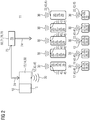
- FIG. 2 is the wiring system 11 according to FIG. 1 imaged after expiration of the inventive method 100.
- the wiring system 11 comprises the control component 10 with a computing unit 15, an input unit 13 and an output unit 14. The functions of the input unit 13 and the output unit 14 are described at the end of the inventive method 100 in FIG FIG. 3 fulfilled wirelessly.
- the first and second radio network addresses 12, 22 include. Between the control component 10 and the first field components 20, wireless connections 30 are formed, via which measurement data, control commands and error messages between the first field components 20 and the control component 10 are exchanged.
- the first field components 20 are designed differently depending on their function and are corresponding sensors 24, actuators, 25, switching devices 26 or safety devices 27.
- Each of the first field components 20 is provided with a microcontroller 28 and a memory 27, which are also suitable, a Store link information 50.
- the first field components 20 are each assigned a first radio network address 12 or a second radio network address 22.
- a first field component 20 with a second radio network address 22 is coupled via a link information 50 with a first radio network address 12 of the control component 10.
- the assignment of a first and a second radio network address 12, 22 defines a wireless connection 30 between an access point 43 of the control component 10 and a first field component 20.
- the control component 10 and the first and second field components 20, 21 are each equipped with a radio unit 45 via the data traffic of the respective wireless link 30 is handled.
- Such wireless connections 30 are configured and manufactured via the inventive method 100.
- first field components 20 are connected to a first radio network address 12 via a link information 50 of a second field component 21 having a second radio network address 22 coupled.
- Such wireless connections 30 are configured and manufactured in the course of the noninventive method.
- the first and second field components 20, 21 are substantially identical in construction and each have a microcontroller 28 and a memory 29 which are suitable for detecting and storing the corresponding linking information 50.
- the linking information 50 is stored in the memories 29 of the first and second field components 20, 21 in such a way that the linking information 50 can be read out and used without further processing when the first and second field components 20, 21 are started up.
- the linking information 50 is assigned to the control component 10 and the first and second field components 20, 21 from the developer tool 70.
- the developer tool 70 has the output interface 73, via which an output 74 of the linking information 50 takes place.
- the developer tool is equipped with a memory 76 and a computing unit 78 which make it possible to execute a program 60 which implements the method 100 according to the invention.
- FIG. 3 the sequence of the method 100 according to the invention is shown schematically.
- a first step 110 the provision of the circuit information 40 takes place, which is designed as CAD information 44.
- the in FIG. 1 represented data access 72, in which the circuit information is read by the developer tool 70, not shown.
- the wire connection 42 is detected which is present between the not-depicted first field component 20 and the control component 10 (not illustrated) and is to be replaced by a wireless connection 30.
- the first end 46 of the wire connection 42 detected in the previous step is assigned a first radio network address 12.
- a second radio network address 22 is assigned to the second end 48 of the wire connection 42 detected in the second step 120 in the fourth step 140.
- a linking information 50 is provided, which comprises the first and second radio network address 12, 22 and forwarded by an output 74 to the control component 10, not shown.
- the output 74 thereby defines the wireless connection 30 between the first field component 20 and the control component 10.
- the wire connection 42 between the first and second field components 20, 21 is detected, which is to be replaced by a wireless connection 30.
- the first and second radio network addresses 12, 22, not shown are assigned to the first and second ends 46, 48 of the wire connection 42, not shown.
Landscapes
- Engineering & Computer Science (AREA)
- Computer Networks & Wireless Communication (AREA)
- Signal Processing (AREA)
- Physics & Mathematics (AREA)
- General Physics & Mathematics (AREA)
- Automation & Control Theory (AREA)
- Small-Scale Networks (AREA)
Claims (10)
- Procédé (100) de configuration d'une liaison (30) sans fil entre un composant (10) de commande et un premier composant (20) sur site de la technique d'automatisation, comprenant les stades :a) mise à disposition d'une information (40) de circuit d'un système (11) de câblage, qui est constituée sous la forme d'une information CAD (44) et qui reproduit la structure du système (11) de câblage,b) détection d'une liaison (42) filaire entre le composant (10) de commande et le premier composant (20) sur site,c) affectation d'une première adresse (12) de réseau radio au composant (10) de commande, la première adresse (12) de réseau radio correspondant à une première extrémité (46) de la liaison (42) filaire,d) affectation d'une deuxième adresse (22) de réseau radio au premier composant (20) sur site, la deuxième adresse (22) de réseau radio correspondant à une deuxième extrémité (48) de la liaison (42) filaire,e) mise à disposition d'une information (50) de combinaison, comprenant la première et la deuxième adresse (12, 22) de réseau radio dans le composant (10) de commande.
- Procédé (100) suivant la revendication 1, caractérisé en ce que la détection de la liaison (42) filaire s'effectue à l'aide d'un identificateur (18) de type mémorisé dans l'information (40) de circuit.
- Procédé (100) suivant l'une des revendications 1 ou 2, caractérisé en ce que la liaison (30) sans fil est constituée sous la forme d'une liaison Bluetooth, d'une liaison Zigbee, d'une liaison WLAN, d'une liaison acoustique ou d'une liaison optique.
- Procédé (100) suivant l'une des revendications 1 à 3, caractérisé en ce que la liaison (30) sans fil est bidirectionnelle.
- Procédé (100) suivant l'une des revendications 1 à 4, caractérisé en ce qu'au stade b), on détecte une pluralité de liaisons (42) filaires et aux stades c) et d), on affecte respectivement une pluralité de première et de deuxième adresses (12, 22) de réseau radio et au stade e), on met à disposition la pluralité de première et deuxième adresses (12, 22) de réseau radio dans l'information (50) de combinaison.
- Procédé (100) suivant la revendication 5, caractérisé en ce que l'on met à disposition l'information (50) de combinaison pour faire fonctionner une unité (45) radio dans le premier composant (20) sur site et/ou le composant (10) de commande.
- Procédé (100) suivant l'une des revendications 1 à 6, caractérisé en ce que le premier composant (20) sur site est constitué en capteur (24), en actionneur (25), en appareil (26) de commutation ou en dispositif (27) de sécurité.
- Procédé (100) suivant l'une des revendications 1 à 7, caractérisé en ce que l'on effectue a) à e), chacun une fois pour chaque composant (20, 21) sur site du système (11) de câblage.
- Programme (60), qui est mémorisé sur un support de mémoire et qui est constitué pour effectuer un procédé suivant l'une des revendications 1 à 8.
- Outil (70) de développement, comprenant une interface (71) d'entrée pour détecter (72) une information (40) de circuit d'un système (11) de câblage, une interface (73) de sortie (74) pour sortir une information (50) de combinaison sur un composant (10) de commande et/ou un composant (20,21) sur site du système (11) de câblage, une mémoire (76) et une unité (78) informatique conçue pour effectuer un procédé suivant l'une des revendications 1 à 8.
Priority Applications (2)
| Application Number | Priority Date | Filing Date | Title |
|---|---|---|---|
| EP14184335.9A EP2996002B1 (fr) | 2014-09-11 | 2014-09-11 | Procédé de configuration pour une connection sans fil |
| US14/834,530 US10044557B2 (en) | 2014-09-11 | 2015-08-25 | Configuration method for a wiring system |
Applications Claiming Priority (1)
| Application Number | Priority Date | Filing Date | Title |
|---|---|---|---|
| EP14184335.9A EP2996002B1 (fr) | 2014-09-11 | 2014-09-11 | Procédé de configuration pour une connection sans fil |
Publications (2)
| Publication Number | Publication Date |
|---|---|
| EP2996002A1 EP2996002A1 (fr) | 2016-03-16 |
| EP2996002B1 true EP2996002B1 (fr) | 2018-02-07 |
Family
ID=51494212
Family Applications (1)
| Application Number | Title | Priority Date | Filing Date |
|---|---|---|---|
| EP14184335.9A Active EP2996002B1 (fr) | 2014-09-11 | 2014-09-11 | Procédé de configuration pour une connection sans fil |
Country Status (2)
| Country | Link |
|---|---|
| US (1) | US10044557B2 (fr) |
| EP (1) | EP2996002B1 (fr) |
Families Citing this family (1)
| Publication number | Priority date | Publication date | Assignee | Title |
|---|---|---|---|---|
| CN107241175A (zh) * | 2017-07-25 | 2017-10-10 | 国电联合动力技术有限公司 | 一种带变桨滑环单元冗余通讯的装置 |
Family Cites Families (6)
| Publication number | Priority date | Publication date | Assignee | Title |
|---|---|---|---|---|
| JP2004128227A (ja) * | 2002-10-02 | 2004-04-22 | Sanyo Electric Co Ltd | 回路装置提供システム及びサーバコンピュータ |
| US7710587B2 (en) * | 2004-10-18 | 2010-05-04 | Microsoft Corporation | Method and system for configuring an electronic device |
| US20080120370A1 (en) * | 2006-11-22 | 2008-05-22 | Brian Chan | Virtual Meeting Server Discovery |
| DE102007048476A1 (de) | 2007-10-09 | 2009-04-16 | Endress + Hauser Process Solutions Ag | Energiesparender Betrieb einer drahtgebundenen Kommunikationsschnittstelle eines Feldgerätes |
| US9405285B2 (en) * | 2011-03-18 | 2016-08-02 | Honeywell International Inc. | Interface for local configuration and monitoring of an industrial field device with support for provisioning onto an industrial wireless network and related system and method |
| US20130072252A1 (en) * | 2011-09-20 | 2013-03-21 | Htc Corporation | Wireless device and wireless connection method thereof |
-
2014
- 2014-09-11 EP EP14184335.9A patent/EP2996002B1/fr active Active
-
2015
- 2015-08-25 US US14/834,530 patent/US10044557B2/en active Active
Non-Patent Citations (1)
| Title |
|---|
| None * |
Also Published As
| Publication number | Publication date |
|---|---|
| US10044557B2 (en) | 2018-08-07 |
| US20160080199A1 (en) | 2016-03-17 |
| EP2996002A1 (fr) | 2016-03-16 |
Similar Documents
| Publication | Publication Date | Title |
|---|---|---|
| EP3298729B1 (fr) | Scan de topologie automatisé | |
| WO2018192712A1 (fr) | Procédé et passerelle en nuage permettant de surveiller une installation de la technique d'automatisation | |
| DE102009045386A1 (de) | Verfahren zum Betreiben eines Feldbus-Interface | |
| DE102011007384A1 (de) | Verfahren zur Offline-Konfiguration eines Feldgeräts | |
| DE102012112842A1 (de) | System und Verfahren zum Einsatz in der Automatisierungstechnik | |
| DE102011078030A1 (de) | Verfahren zum Betreiben eines Feldgerätes | |
| WO2018197197A1 (fr) | Procédé permettant de faire fonctionner un appareil de terrain | |
| DE102016124350A1 (de) | Verfahren und System zum Überwachen einer Anlage der Prozessautomatisierung | |
| WO2020239434A1 (fr) | Procédé de détection d'abonnés du réseau dans un réseau d'automatisation et réseau d'automatisation | |
| EP4345556A1 (fr) | Procédé d'installation assistée par ordinateur de composants agencés de manière décentralisée dans l'espace d'une machine | |
| DE112014004208T5 (de) | Integrationsverfahren und -System | |
| EP3616011B1 (fr) | Dispositif et procédé de surveillance d'un système d'automatisation | |
| EP2765465A1 (fr) | Module de communication à bus de terrain et son procédé de fonctionnement | |
| DE112011105487B4 (de) | Analogeingabesystem, Analogausgabesystem und Analogeingabe-/ausgabesystem | |
| EP2996002B1 (fr) | Procédé de configuration pour une connection sans fil | |
| DE102016123599A1 (de) | Robotersteuerung mit Funktion zur Kommunikation mit einer speicherprogrammierbaren Steuerung und Kommunikationssystem | |
| DE102019134895A1 (de) | Verfahren zum rückführungsfreien Übertragen feldgerätebezogener Daten | |
| DE102010040054A1 (de) | Verfahren zur Sicherstellung der korrekten Funktionsweise einer Automatisierungsanlage | |
| DE102011006728B4 (de) | Verfahren zur Erzeugung eines Blinksignals an einem Slave in einem Master-Slave-Bussystem der Automatisierungstechnik | |
| WO2012155949A1 (fr) | Procédé permettant de faire fonctionner un système d'automatisation | |
| WO2016079091A1 (fr) | Procédé de fonctionnement d'un premier et d'au moins un deuxième appareil de terrain | |
| EP3163389B1 (fr) | Procede de configuration d'appareils de terrain et appareil de terrain ayant une configuration pour deux systemes de bus | |
| EP2507974B1 (fr) | Communication entre des éléments d'un système | |
| DE102017123224A1 (de) | Verfahren zum Etablieren einer Netzwerkkommunikation mittels OPC UA | |
| EP2899603B1 (fr) | Projection de système de bus de terrain |
Legal Events
| Date | Code | Title | Description |
|---|---|---|---|
| PUAI | Public reference made under article 153(3) epc to a published international application that has entered the european phase |
Free format text: ORIGINAL CODE: 0009012 |
|
| AK | Designated contracting states |
Kind code of ref document: A1 Designated state(s): AL AT BE BG CH CY CZ DE DK EE ES FI FR GB GR HR HU IE IS IT LI LT LU LV MC MK MT NL NO PL PT RO RS SE SI SK SM TR |
|
| AX | Request for extension of the european patent |
Extension state: BA ME |
|
| 17P | Request for examination filed |
Effective date: 20160914 |
|
| RBV | Designated contracting states (corrected) |
Designated state(s): AL AT BE BG CH CY CZ DE DK EE ES FI FR GB GR HR HU IE IS IT LI LT LU LV MC MK MT NL NO PL PT RO RS SE SI SK SM TR |
|
| R17P | Request for examination filed (corrected) |
Effective date: 20160914 |
|
| 17Q | First examination report despatched |
Effective date: 20161021 |
|
| RAP1 | Party data changed (applicant data changed or rights of an application transferred) |
Owner name: SIEMENS AKTIENGESELLSCHAFT |
|
| GRAP | Despatch of communication of intention to grant a patent |
Free format text: ORIGINAL CODE: EPIDOSNIGR1 |
|
| INTG | Intention to grant announced |
Effective date: 20171006 |
|
| GRAS | Grant fee paid |
Free format text: ORIGINAL CODE: EPIDOSNIGR3 |
|
| GRAA | (expected) grant |
Free format text: ORIGINAL CODE: 0009210 |
|
| AK | Designated contracting states |
Kind code of ref document: B1 Designated state(s): AL AT BE BG CH CY CZ DE DK EE ES FI FR GB GR HR HU IE IS IT LI LT LU LV MC MK MT NL NO PL PT RO RS SE SI SK SM TR |
|
| REG | Reference to a national code |
Ref country code: GB Ref legal event code: FG4D Free format text: NOT ENGLISH |
|
| REG | Reference to a national code |
Ref country code: AT Ref legal event code: REF Ref document number: 969029 Country of ref document: AT Kind code of ref document: T Effective date: 20180215 Ref country code: CH Ref legal event code: EP |
|
| REG | Reference to a national code |
Ref country code: IE Ref legal event code: FG4D Free format text: LANGUAGE OF EP DOCUMENT: GERMAN |
|
| REG | Reference to a national code |
Ref country code: DE Ref legal event code: R096 Ref document number: 502014007192 Country of ref document: DE |
|
| REG | Reference to a national code |
Ref country code: NL Ref legal event code: MP Effective date: 20180207 |
|
| PG25 | Lapsed in a contracting state [announced via postgrant information from national office to epo] |
Ref country code: CY Free format text: LAPSE BECAUSE OF FAILURE TO SUBMIT A TRANSLATION OF THE DESCRIPTION OR TO PAY THE FEE WITHIN THE PRESCRIBED TIME-LIMIT Effective date: 20180207 Ref country code: HR Free format text: LAPSE BECAUSE OF FAILURE TO SUBMIT A TRANSLATION OF THE DESCRIPTION OR TO PAY THE FEE WITHIN THE PRESCRIBED TIME-LIMIT Effective date: 20180207 Ref country code: NL Free format text: LAPSE BECAUSE OF FAILURE TO SUBMIT A TRANSLATION OF THE DESCRIPTION OR TO PAY THE FEE WITHIN THE PRESCRIBED TIME-LIMIT Effective date: 20180207 Ref country code: LT Free format text: LAPSE BECAUSE OF FAILURE TO SUBMIT A TRANSLATION OF THE DESCRIPTION OR TO PAY THE FEE WITHIN THE PRESCRIBED TIME-LIMIT Effective date: 20180207 Ref country code: FI Free format text: LAPSE BECAUSE OF FAILURE TO SUBMIT A TRANSLATION OF THE DESCRIPTION OR TO PAY THE FEE WITHIN THE PRESCRIBED TIME-LIMIT Effective date: 20180207 Ref country code: ES Free format text: LAPSE BECAUSE OF FAILURE TO SUBMIT A TRANSLATION OF THE DESCRIPTION OR TO PAY THE FEE WITHIN THE PRESCRIBED TIME-LIMIT Effective date: 20180207 Ref country code: NO Free format text: LAPSE BECAUSE OF FAILURE TO SUBMIT A TRANSLATION OF THE DESCRIPTION OR TO PAY THE FEE WITHIN THE PRESCRIBED TIME-LIMIT Effective date: 20180507 |
|
| PG25 | Lapsed in a contracting state [announced via postgrant information from national office to epo] |
Ref country code: IS Free format text: LAPSE BECAUSE OF FAILURE TO SUBMIT A TRANSLATION OF THE DESCRIPTION OR TO PAY THE FEE WITHIN THE PRESCRIBED TIME-LIMIT Effective date: 20180607 Ref country code: BG Free format text: LAPSE BECAUSE OF FAILURE TO SUBMIT A TRANSLATION OF THE DESCRIPTION OR TO PAY THE FEE WITHIN THE PRESCRIBED TIME-LIMIT Effective date: 20180507 Ref country code: LV Free format text: LAPSE BECAUSE OF FAILURE TO SUBMIT A TRANSLATION OF THE DESCRIPTION OR TO PAY THE FEE WITHIN THE PRESCRIBED TIME-LIMIT Effective date: 20180207 Ref country code: SE Free format text: LAPSE BECAUSE OF FAILURE TO SUBMIT A TRANSLATION OF THE DESCRIPTION OR TO PAY THE FEE WITHIN THE PRESCRIBED TIME-LIMIT Effective date: 20180207 Ref country code: RS Free format text: LAPSE BECAUSE OF FAILURE TO SUBMIT A TRANSLATION OF THE DESCRIPTION OR TO PAY THE FEE WITHIN THE PRESCRIBED TIME-LIMIT Effective date: 20180207 Ref country code: PL Free format text: LAPSE BECAUSE OF FAILURE TO SUBMIT A TRANSLATION OF THE DESCRIPTION OR TO PAY THE FEE WITHIN THE PRESCRIBED TIME-LIMIT Effective date: 20180207 Ref country code: GR Free format text: LAPSE BECAUSE OF FAILURE TO SUBMIT A TRANSLATION OF THE DESCRIPTION OR TO PAY THE FEE WITHIN THE PRESCRIBED TIME-LIMIT Effective date: 20180508 |
|
| REG | Reference to a national code |
Ref country code: FR Ref legal event code: PLFP Year of fee payment: 5 |
|
| PG25 | Lapsed in a contracting state [announced via postgrant information from national office to epo] |
Ref country code: MT Free format text: LAPSE BECAUSE OF FAILURE TO SUBMIT A TRANSLATION OF THE DESCRIPTION OR TO PAY THE FEE WITHIN THE PRESCRIBED TIME-LIMIT Effective date: 20180207 |
|
| PG25 | Lapsed in a contracting state [announced via postgrant information from national office to epo] |
Ref country code: EE Free format text: LAPSE BECAUSE OF FAILURE TO SUBMIT A TRANSLATION OF THE DESCRIPTION OR TO PAY THE FEE WITHIN THE PRESCRIBED TIME-LIMIT Effective date: 20180207 Ref country code: RO Free format text: LAPSE BECAUSE OF FAILURE TO SUBMIT A TRANSLATION OF THE DESCRIPTION OR TO PAY THE FEE WITHIN THE PRESCRIBED TIME-LIMIT Effective date: 20180207 Ref country code: AL Free format text: LAPSE BECAUSE OF FAILURE TO SUBMIT A TRANSLATION OF THE DESCRIPTION OR TO PAY THE FEE WITHIN THE PRESCRIBED TIME-LIMIT Effective date: 20180207 |
|
| REG | Reference to a national code |
Ref country code: DE Ref legal event code: R097 Ref document number: 502014007192 Country of ref document: DE |
|
| PG25 | Lapsed in a contracting state [announced via postgrant information from national office to epo] |
Ref country code: SM Free format text: LAPSE BECAUSE OF FAILURE TO SUBMIT A TRANSLATION OF THE DESCRIPTION OR TO PAY THE FEE WITHIN THE PRESCRIBED TIME-LIMIT Effective date: 20180207 Ref country code: DK Free format text: LAPSE BECAUSE OF FAILURE TO SUBMIT A TRANSLATION OF THE DESCRIPTION OR TO PAY THE FEE WITHIN THE PRESCRIBED TIME-LIMIT Effective date: 20180207 Ref country code: SK Free format text: LAPSE BECAUSE OF FAILURE TO SUBMIT A TRANSLATION OF THE DESCRIPTION OR TO PAY THE FEE WITHIN THE PRESCRIBED TIME-LIMIT Effective date: 20180207 Ref country code: CZ Free format text: LAPSE BECAUSE OF FAILURE TO SUBMIT A TRANSLATION OF THE DESCRIPTION OR TO PAY THE FEE WITHIN THE PRESCRIBED TIME-LIMIT Effective date: 20180207 |
|
| PLBE | No opposition filed within time limit |
Free format text: ORIGINAL CODE: 0009261 |
|
| STAA | Information on the status of an ep patent application or granted ep patent |
Free format text: STATUS: NO OPPOSITION FILED WITHIN TIME LIMIT |
|
| 26N | No opposition filed |
Effective date: 20181108 |
|
| PG25 | Lapsed in a contracting state [announced via postgrant information from national office to epo] |
Ref country code: SI Free format text: LAPSE BECAUSE OF FAILURE TO SUBMIT A TRANSLATION OF THE DESCRIPTION OR TO PAY THE FEE WITHIN THE PRESCRIBED TIME-LIMIT Effective date: 20180207 |
|
| PG25 | Lapsed in a contracting state [announced via postgrant information from national office to epo] |
Ref country code: MC Free format text: LAPSE BECAUSE OF FAILURE TO SUBMIT A TRANSLATION OF THE DESCRIPTION OR TO PAY THE FEE WITHIN THE PRESCRIBED TIME-LIMIT Effective date: 20180207 |
|
| REG | Reference to a national code |
Ref country code: CH Ref legal event code: PL |
|
| GBPC | Gb: european patent ceased through non-payment of renewal fee |
Effective date: 20180911 |
|
| REG | Reference to a national code |
Ref country code: BE Ref legal event code: MM Effective date: 20180930 |
|
| REG | Reference to a national code |
Ref country code: IE Ref legal event code: MM4A |
|
| PG25 | Lapsed in a contracting state [announced via postgrant information from national office to epo] |
Ref country code: LU Free format text: LAPSE BECAUSE OF NON-PAYMENT OF DUE FEES Effective date: 20180911 |
|
| PG25 | Lapsed in a contracting state [announced via postgrant information from national office to epo] |
Ref country code: IE Free format text: LAPSE BECAUSE OF NON-PAYMENT OF DUE FEES Effective date: 20180911 |
|
| PG25 | Lapsed in a contracting state [announced via postgrant information from national office to epo] |
Ref country code: LI Free format text: LAPSE BECAUSE OF NON-PAYMENT OF DUE FEES Effective date: 20180930 Ref country code: CH Free format text: LAPSE BECAUSE OF NON-PAYMENT OF DUE FEES Effective date: 20180930 Ref country code: BE Free format text: LAPSE BECAUSE OF NON-PAYMENT OF DUE FEES Effective date: 20180930 |
|
| PG25 | Lapsed in a contracting state [announced via postgrant information from national office to epo] |
Ref country code: GB Free format text: LAPSE BECAUSE OF NON-PAYMENT OF DUE FEES Effective date: 20180911 |
|
| PG25 | Lapsed in a contracting state [announced via postgrant information from national office to epo] |
Ref country code: TR Free format text: LAPSE BECAUSE OF FAILURE TO SUBMIT A TRANSLATION OF THE DESCRIPTION OR TO PAY THE FEE WITHIN THE PRESCRIBED TIME-LIMIT Effective date: 20180207 |
|
| PG25 | Lapsed in a contracting state [announced via postgrant information from national office to epo] |
Ref country code: PT Free format text: LAPSE BECAUSE OF FAILURE TO SUBMIT A TRANSLATION OF THE DESCRIPTION OR TO PAY THE FEE WITHIN THE PRESCRIBED TIME-LIMIT Effective date: 20180207 |
|
| PG25 | Lapsed in a contracting state [announced via postgrant information from national office to epo] |
Ref country code: MK Free format text: LAPSE BECAUSE OF NON-PAYMENT OF DUE FEES Effective date: 20180207 Ref country code: HU Free format text: LAPSE BECAUSE OF FAILURE TO SUBMIT A TRANSLATION OF THE DESCRIPTION OR TO PAY THE FEE WITHIN THE PRESCRIBED TIME-LIMIT; INVALID AB INITIO Effective date: 20140911 |
|
| REG | Reference to a national code |
Ref country code: AT Ref legal event code: MM01 Ref document number: 969029 Country of ref document: AT Kind code of ref document: T Effective date: 20190911 |
|
| PG25 | Lapsed in a contracting state [announced via postgrant information from national office to epo] |
Ref country code: AT Free format text: LAPSE BECAUSE OF NON-PAYMENT OF DUE FEES Effective date: 20190911 |
|
| P01 | Opt-out of the competence of the unified patent court (upc) registered |
Effective date: 20230512 |
|
| PGFP | Annual fee paid to national office [announced via postgrant information from national office to epo] |
Ref country code: IT Payment date: 20230920 Year of fee payment: 10 |
|
| PGFP | Annual fee paid to national office [announced via postgrant information from national office to epo] |
Ref country code: FR Payment date: 20230918 Year of fee payment: 10 |
|
| PG25 | Lapsed in a contracting state [announced via postgrant information from national office to epo] |
Ref country code: IT Free format text: LAPSE BECAUSE OF NON-PAYMENT OF DUE FEES Effective date: 20240911 |
|
| PG25 | Lapsed in a contracting state [announced via postgrant information from national office to epo] |
Ref country code: FR Free format text: LAPSE BECAUSE OF NON-PAYMENT OF DUE FEES Effective date: 20240930 |
|
| PGFP | Annual fee paid to national office [announced via postgrant information from national office to epo] |
Ref country code: DE Payment date: 20250714 Year of fee payment: 12 |