EP2996120A1 - Dispositif de support pour une bobine de choc à noyau toroïdal et composant inductif - Google Patents
Dispositif de support pour une bobine de choc à noyau toroïdal et composant inductif Download PDFInfo
- Publication number
- EP2996120A1 EP2996120A1 EP15188963.1A EP15188963A EP2996120A1 EP 2996120 A1 EP2996120 A1 EP 2996120A1 EP 15188963 A EP15188963 A EP 15188963A EP 2996120 A1 EP2996120 A1 EP 2996120A1
- Authority
- EP
- European Patent Office
- Prior art keywords
- fastening devices
- toroidal core
- carrier device
- latching
- base plate
- Prior art date
- Legal status (The legal status is an assumption and is not a legal conclusion. Google has not performed a legal analysis and makes no representation as to the accuracy of the status listed.)
- Granted
Links
Images



Classifications
-
- H—ELECTRICITY
- H01—ELECTRIC ELEMENTS
- H01F—MAGNETS; INDUCTANCES; TRANSFORMERS; SELECTION OF MATERIALS FOR THEIR MAGNETIC PROPERTIES
- H01F27/00—Details of transformers or inductances, in general
- H01F27/02—Casings
- H01F27/027—Casings specially adapted for combination of signal type inductors or transformers with electronic circuits, e.g. mounting on printed circuit boards
-
- H—ELECTRICITY
- H01—ELECTRIC ELEMENTS
- H01F—MAGNETS; INDUCTANCES; TRANSFORMERS; SELECTION OF MATERIALS FOR THEIR MAGNETIC PROPERTIES
- H01F17/00—Fixed inductances of the signal type
- H01F17/04—Fixed inductances of the signal type with magnetic core
- H01F17/06—Fixed inductances of the signal type with magnetic core with core substantially closed in itself, e.g. toroid
- H01F17/062—Toroidal core with turns of coil around it
Definitions
- a carrier device for a toroidal core choke will be described. Furthermore, a holder for an inductive component comprising the carrier device and an inductive component with the holder is described.
- An insulating part is z. B. from the document DE 10223995 C1 known.
- the insulating part engages around the ring core of a toroidal core choke and has projections for fixing wire windings and for maintaining a grid dimension.
- the insulating part has webs in the middle region, which provide the potential separation.
- Another insulating part is z. B. from the document DE 10308010 A1 known.
- the insulating part has radially outwardly extending webs, which are elastically deformable by the pressure in the radial direction.
- An object to be solved is to specify a carrier device for a toroidal core choke.
- a housing part or a carrier device serve as a housing part or a carrier device.
- a support device is specified for a toroidal core, which has a latching device for fastening a Has holding device for the toroidal core.
- the holding device can be fastened in the toroidal core preferably by means of elastic forces.
- the holding device and the carrier device are preferably each formed from an electrically insulating material.
- plastics suitable for injection molding are suitable.
- the specified carrier device and the specified holding device form in an advantageous variant of a holder or a partial housing of an inductive component with a toroidal core choke, wherein the locking devices of the holding device and the carrier device are formed complementary to each other.
- the latching device of a holding device or a carrier device is preferably designed as a latching surface.
- the locking surface can, for. B. have a ribbing.
- the locking devices are preferably arranged on both end sides of the holding device.
- a part of the holding device carrying the latching devices is preferably designed to protrude over the remaining parts of the holding device.
- the holding device can, for. B. may be provided as a potential separation device in a toroidal core choke with multiple windings.
- You can z. B. comprise a star-shaped arrangement of a plurality of webs, wherein at least one of the webs has a latching device, preferably a latching surface.
- the holding device comprises a central part and at least two outwardly extending, elastically deformable webs which can be wound around the middle part and which each have a rigid insulating region at their end remote from the middle part.
- a latching device is arranged on the rigid insulating region.
- at least one latching surface are arranged on both end sides of the insulating region.
- a locking device on the central part - preferably also frontally - be arranged.
- the latching device of the carrier device may comprise two opposing latching surfaces.
- the holding device for a ring core is preferably fastened between these latching surfaces.
- the support device comprises a base plate having protruding, elongated attachment devices and a region disposed between them for receiving a toroidal core choke.
- the fastening devices preferably extend perpendicular to the base plate and have the shape of a rod.
- a toroidal core choke is arranged in a variant between two preferably in a transverse direction opposite each other fastening devices standing.
- a fastening device has at least one latching device facing the throttle region, preferably a latching surface.
- a fastening device may have elongated projections which laterally delimit the latching surface. The remote from the base plate ends of the projections are preferably chamfered.
- the fastening devices are provided in an advantageous variant, also for wire guidance or to comply with the grid dimension of a wire winding of the toroidal core choke.
- they preferably have at least one wire guide channel which runs parallel to the axis of the fastening device or perpendicular to the base plate. The ends of one of the wire windings are guided in the wire guide channels of the fastening devices.
- a wire guide channel is preferably formed as a groove on the side facing away from the throttle region side of the fastening device.
- a fastening device is thus preferably for a plurality of purposes, d. H. used both for fixing the holding device as well as wire guide.
- a multifunctional fastening device preferably has an H-profile.
- the base plate preferably at least two wire feedthrough openings are provided for receiving ends of a wire winding.
- the wire guide channel of a holding device opens into one of these openings.
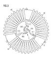
- a potential separation device 5 used in the core hole of the toroidal core 2 of a toroidal core choke is shown in FIG. 3 shown.
- the potential separation device 5 serves as a spacer between wire windings 41, 42, 43 of the toroidal core choke.
- an electrical isolation device 5 may include any toroidal core support.
- toroidal core choke comprises a toroidal core 2 and three wound on this core wire windings 41, 42, 43, each of which is at its own electrical potential.
- the potential separation device 5 is preferably fixed in the core hole by means of elastic forces acting in the radial direction.
- the potential separation device 5 has a central portion 55 and three outgoing from this, star-shaped extending, in this variant elastically deformable webs 501, 502, 503, at the ends facing away from the center insulating regions 511, 512, 513 are provided.
- potential separation device 5 may be dimensionally stable in another variant and have at their ends facing the toroidal elastically deformable, preferably spreadable devices that press upon insertion of the potential separation device 5 in a core hole against the inner wall of the core hole.
- the webs 521, 522, 523 are arranged in a star shape.
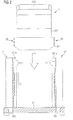
- FIGS. 1 and 2 is indicated by a block arrow that the potential separation device 5 - preferably inserted after insertion into the core hole of a ring core - between the fastening devices 11 and 12 and between this is fixed by means of locking devices 50, 113 in the vertical direction and by means of projections 111, 112 and 121, 122 of the fastening devices 11, 12 in the longitudinal direction.
- latching devices 50 designed as ribs are formed on both end sides of the rigid insulating region 511.
- the rigid insulating region 511 that is to say the part of the potential separation device 5 carrying the latching devices 50, protrudes in the axial direction on both sides beyond remaining parts of the potential separation device.
- the axial size of the remaining parts of the potential separation device is adapted to the axial size of the toroidal core, wherein the insulating region 511 protrudes on both sides of the core and thus suitable for fixing the arrangement of the potential separation device 5 and the core 2.
- FIG. 2 is only one projection 111 or 121 of the fastening device 11 and 12 visible.
- An upper end of the projection 111, 121 has a tapered surface 111a, 121a, respectively.
- beveled surfaces of the projections which are associated with the same fastening device, facing each other, see Fig. 4 ,
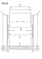
- FIG. 2A is the bracket according to FIGS. 1 and 2 shown after locking the potential separation device 5 between fasteners 11 and 12.
- the locking devices of a fastening device and the potential separation device are positively adapted to each other.
- the locking devices 50, 113, 123 are designed as a locking mechanism, wherein the movement of the potential separation device 5 is prevented upwards by the preferred direction of the toothing.
- FIGS. 4 to 6 a further advantageous embodiment of a carrier device for a toroidal core choke is shown in different views.
- FIGS. 8 to 10 different views of a holder are shown, which comprises this support device and an insertable into a core hole potential separation device 5.
- the support device according to the second embodiment is preferably substantially the same as the support device according to the first embodiment except for the differences explained below and apparent from the figures.
- the fastening devices 11 and 12 are mirror-symmetrical. Their design will be explained with reference to the fastening device 11.
- FIG. 4 shows a partial cross-sectional view of the support device according to the second embodiment with a view of the fastening device 11 from the inside.
- the fastening device 11 has on its inner side facing the ring core hole a latching device 113, which is designed here as a latching surface with a ribbing.
- the ribbing extends along the axis of the fastening device 11.
- the ribbing is designed so that the sliding of a potential separation device 5 to the base plate 10 out possible, but the sliding in the opposite direction is prevented.
- the latching device 113 is bounded on both sides by rails 111 and 112.
- the rails 111 and 112 are in the direction of the toroidal core choke facing projections of the fastening device 11. These rails are parallel to the axis of the fastening device.
- the rails 111 and 112 are tapered towards the top of the fastening device such that the introduction of a potential separation device 5 is facilitated.
- the part of the potential separating device 5 facing the fastening device 11 is preferably designed such that it can glide smoothly between the rails 111, 112, but can not slip off laterally.
- FIG. 5 A side view of the carrier device according to FIG. 4 is in FIG. 5 shown. In this case, the outside of the fastening device 11 can be seen.
- the fastening devices 11, 12 each have a substantially H-profile.
- the base plate 10 is divided in a longitudinal direction x into two edge regions and a middle region.
- the fastening devices 11, 12 are arranged in the central region of the base plate 10.
- the fastening devices 11, 12 are transverse to the longitudinal direction x of the base plate 10 facing each other.
- a throttle region for receiving a toroidal core choke is provided between the fastening devices 11, 12 .
- Two wire feedthrough openings 101 and 102, 103 and 104, 105 and 106 are provided per area.
- the openings 101 to 106 are arranged in pairs along a transverse direction y.
- the pairs of openings serve in each case to maintain the grid dimension of ends 31, 32, 33 of the respective wire winding 41, 42, 43.
- the openings 101 and 102 serve to carry out both ends 32 of the wire winding 42.
- the openings 103 and 104 serve for the passage of ends 33 of the wire winding 43 and the openings 105 and 106 for the passage of ends 31 of the wire winding 41.
- the wire guide channels of the fastening devices 11 and 12 open into the openings 103 and 104, respectively.
- the carrier device is preferably mirror-symmetrical with respect to an axis extending through its center, parallel to the direction x or y.
- spacer feet 60 are arranged for spacing between the base plate 10 and a circuit board, not shown here, provided for mounting the inductive component.
- End portions of the wire coil 43 are fixed by the walls of the fastening devices 11, 12.
- these end cuts are recessed in the respective wire guide channel, so that the wire section in cross section on the open side of the fastening devices 11, 12 does not project beyond these devices.
- the end portions of the wire winding 43 are guided in the wire guide channel and thereby fixed in the axial direction of the wire guide channel, ie perpendicular to the base plate 10. Characterized in that transverse to the base plate 10 extending end portions of the wire winding 43 are respectively fixed in the wire guide channel of the fastening device 11 and 12, wherein their lateral slipping is prevented, the position of the toroidal core choke relative to the base plate 10 is fixed.
- the fastening devices 11, 12 each serve for a secure spacing of the wire ends 33 of the wire winding 43 from the other wire windings 41, 42. This makes it possible to use wire windings without an insulating sheath. It can be used with an insulating varnish or possibly even not insulated wire windings.
- the fastening devices 11, 12 may have any cross-section or the wire guide channel with an arbitrary cross-section.
- the fastening devices 11, 12 may be formed in a variant as a hollow tube or hollow cylinder.
- the cross section of the wire guide channel is preferably adapted to the shape of the wire end 33.
- the base plate 10 and its fastening devices 11, 12 are preferably produced in one piece, ie in one method step. But it is also possible to manufacture the base plate 10 and the fastening devices 11, 12 made of a material or of different materials separately and firmly, preferably monolithically connect to each other. It is also possible initially to provide the base plate 10 and to produce the fastening devices 11, 12 thereon in a later method step.
Landscapes
- Engineering & Computer Science (AREA)
- Power Engineering (AREA)
- Coils Or Transformers For Communication (AREA)
Applications Claiming Priority (2)
| Application Number | Priority Date | Filing Date | Title |
|---|---|---|---|
| DE102005027942A DE102005027942A1 (de) | 2005-06-16 | 2005-06-16 | Haltevorrichtung, Trägervorrichtung für eine Ringkerndrossel und induktives Bauelement |
| EP06753215.0A EP1891647B1 (fr) | 2005-06-16 | 2006-05-31 | Dispositif de retenue, dispositif de support pour une bobine de choc a noyau toroidal et composant inductif |
Related Parent Applications (2)
| Application Number | Title | Priority Date | Filing Date |
|---|---|---|---|
| EP06753215.0A Division EP1891647B1 (fr) | 2005-06-16 | 2006-05-31 | Dispositif de retenue, dispositif de support pour une bobine de choc a noyau toroidal et composant inductif |
| EP06753215.0A Division-Into EP1891647B1 (fr) | 2005-06-16 | 2006-05-31 | Dispositif de retenue, dispositif de support pour une bobine de choc a noyau toroidal et composant inductif |
Publications (2)
| Publication Number | Publication Date |
|---|---|
| EP2996120A1 true EP2996120A1 (fr) | 2016-03-16 |
| EP2996120B1 EP2996120B1 (fr) | 2017-06-28 |
Family
ID=36782554
Family Applications (2)
| Application Number | Title | Priority Date | Filing Date |
|---|---|---|---|
| EP15188963.1A Active EP2996120B1 (fr) | 2005-06-16 | 2006-05-31 | Dispositif de support pour une bobine de choc à noyau toroïdal et composant inductif |
| EP06753215.0A Active EP1891647B1 (fr) | 2005-06-16 | 2006-05-31 | Dispositif de retenue, dispositif de support pour une bobine de choc a noyau toroidal et composant inductif |
Family Applications After (1)
| Application Number | Title | Priority Date | Filing Date |
|---|---|---|---|
| EP06753215.0A Active EP1891647B1 (fr) | 2005-06-16 | 2006-05-31 | Dispositif de retenue, dispositif de support pour une bobine de choc a noyau toroidal et composant inductif |
Country Status (6)
| Country | Link |
|---|---|
| US (1) | US7479865B2 (fr) |
| EP (2) | EP2996120B1 (fr) |
| JP (1) | JP4886776B2 (fr) |
| CN (1) | CN101199031B (fr) |
| DE (1) | DE102005027942A1 (fr) |
| WO (1) | WO2006133671A1 (fr) |
Families Citing this family (33)
| Publication number | Priority date | Publication date | Assignee | Title |
|---|---|---|---|---|
| US8624702B2 (en) * | 2004-06-17 | 2014-01-07 | Grant A. MacLennan | Inductor mounting apparatus and method of use thereof |
| US8373530B2 (en) | 2004-06-17 | 2013-02-12 | Grant A. MacLennan | Power converter method and apparatus |
| US8624696B2 (en) * | 2004-06-17 | 2014-01-07 | Grant A. MacLennan | Inductor apparatus and method of manufacture thereof |
| US8203411B2 (en) * | 2004-06-17 | 2012-06-19 | Maclennan Grant A | Potted inductor apparatus and method of use thereof |
| US8902035B2 (en) | 2004-06-17 | 2014-12-02 | Grant A. MacLennan | Medium / high voltage inductor apparatus and method of use thereof |
| US9300197B2 (en) | 2004-06-17 | 2016-03-29 | Grant A. MacLennan | High frequency inductor filter apparatus and method of use thereof |
| US8089333B2 (en) * | 2004-06-17 | 2012-01-03 | Maclennan Grant A | Inductor mount method and apparatus |
| US8009008B2 (en) * | 2004-06-17 | 2011-08-30 | Ctm Magnetics, Inc. | Inductor mounting, temperature control, and filtering method and apparatus |
| US9257895B2 (en) | 2004-06-17 | 2016-02-09 | Grant A. MacLennan | Distributed gap inductor filter apparatus and method of use thereof |
| US8519813B2 (en) * | 2004-06-17 | 2013-08-27 | Grant A. MacLennan | Liquid cooled inductor apparatus and method of use thereof |
| US8902034B2 (en) | 2004-06-17 | 2014-12-02 | Grant A. MacLennan | Phase change inductor cooling apparatus and method of use thereof |
| DE102004039230A1 (de) * | 2004-08-12 | 2006-02-23 | Epcos Ag | Induktives Bauelement für hohe Ströme und Verfahren zu dessen Herstellung |
| DE102005006344A1 (de) * | 2005-02-11 | 2006-08-17 | Epcos Ag | Isolierteil und Ringkerndrossel |
| DE102005010342A1 (de) * | 2005-03-07 | 2006-09-14 | Epcos Ag | Induktives Bauelement |
| US8947187B2 (en) | 2005-06-17 | 2015-02-03 | Grant A. MacLennan | Inductor apparatus and method of manufacture thereof |
| US8125777B1 (en) | 2008-07-03 | 2012-02-28 | Ctm Magnetics, Inc. | Methods and apparatus for electrical components |
| US8816808B2 (en) | 2007-08-22 | 2014-08-26 | Grant A. MacLennan | Method and apparatus for cooling an annular inductor |
| DE102009054001A1 (de) * | 2009-11-19 | 2011-08-04 | Epcos Ag, 81669 | Vorrichtung zur Potentialtrennung und Ringkerndrossel |
| DE102011087117B4 (de) * | 2011-11-25 | 2023-07-20 | Hilti Aktiengesellschaft | Elektrischer Antrieb für eine Handwerkzeugmaschine |
| JP5967472B2 (ja) * | 2012-04-20 | 2016-08-10 | 日立金属株式会社 | コイル部品 |
| JP2014204100A (ja) * | 2013-04-10 | 2014-10-27 | 本田技研工業株式会社 | チョークコイルおよび電子機器 |
| DE102013213404A1 (de) * | 2013-07-09 | 2015-01-15 | Vacuumschmelze Gmbh & Co. Kg | Induktives Bauelement |
| JP6161206B2 (ja) * | 2014-03-05 | 2017-07-12 | コーセル株式会社 | ノイズフィルタ |
| CN104392824B (zh) * | 2014-12-05 | 2017-03-15 | 贵州长通电气有限公司 | 一种互感器定位装置及定位方法 |
| DE102015104794A1 (de) | 2015-03-27 | 2016-09-29 | Epcos Ag | Induktives Bauelement sowie Verfahren zur Herstellung eines induktiven Bauelements |
| DE102016206171A1 (de) | 2016-04-13 | 2017-10-19 | Würth Elektronik eiSos Gmbh & Co. KG | Trennelement für eine Ringkerndrossel und Ringkerndrossel |
| DE102016107818B4 (de) * | 2016-04-27 | 2018-01-25 | Sma Solar Technology Ag | Drosselanordnung mit einem Einsatz |
| DE102016209613A1 (de) | 2016-06-01 | 2017-12-07 | Würth Elektronik eiSos Gmbh & Co. KG | Montagesatz für eine Drossel und Drossel |
| CN106158249A (zh) * | 2016-08-30 | 2016-11-23 | 合肥博雷电气有限公司 | 一种表面黏着高频铁芯的阻抗元件 |
| DE102017214857B4 (de) * | 2017-08-24 | 2024-08-01 | Vacuumschmelze Gmbh & Co. Kg | Ringkernbaugruppe, stromkompensierte Drossel und Verfahren zur Herstellung einer Ringkernbaugruppe |
| DE102018115283A1 (de) * | 2018-02-28 | 2019-08-29 | Hanon Systems | Drosselanordnung und Aufnahme für die Drosselanordnung |
| ES2930244T3 (es) * | 2020-04-30 | 2022-12-09 | Fronius Int Gmbh | Dispositivo de filtrado |
| CN113923920B (zh) * | 2020-07-09 | 2023-05-09 | 比亚迪股份有限公司 | 滤波模块和具有其的电子设备 |
Citations (8)
| Publication number | Priority date | Publication date | Assignee | Title |
|---|---|---|---|---|
| DE3047603A1 (de) * | 1980-12-17 | 1982-07-22 | Siemens AG, 1000 Berlin und 8000 München | Ringkerndrossel |
| JPS5970324U (ja) * | 1982-11-02 | 1984-05-12 | 東北金属工業株式会社 | コンモンチヨ−クコイル |
| DE3330881A1 (de) * | 1983-08-26 | 1985-03-14 | Siemens AG, 1000 Berlin und 8000 München | Halterung fuer eine insbesondere stromkompensierte ferrit-ringkerndrossel |
| JPH0546009U (ja) * | 1991-11-25 | 1993-06-18 | 株式会社トーキン | 端子台付コイル |
| JPH0645310U (ja) * | 1992-11-25 | 1994-06-14 | 株式会社トーキン | コモンモードコイル |
| JP3006873U (ja) * | 1994-07-18 | 1995-01-31 | 富士電気化学株式会社 | チョークコイル用取付台 |
| DE10223995C1 (de) | 2002-05-29 | 2003-11-27 | Epcos Ag | Spulenkörper und Kerndrossel mit dem Spulenkörper |
| DE10308010A1 (de) | 2003-02-25 | 2004-09-09 | Epcos Ag | Isolierteil, Ringkern, Ringkerndrossel und Verfahren zur Herstellung der Ringkerndrossel |
Family Cites Families (6)
| Publication number | Priority date | Publication date | Assignee | Title |
|---|---|---|---|---|
| DE3636065C1 (de) * | 1986-10-23 | 1988-04-28 | Klaus Lorenzen | Halterung von elektrischen Bauelementen auf einer Schaltungsplatte |
| DE4321872A1 (de) * | 1993-07-01 | 1995-02-23 | Taller Gmbh | Halterung für eine Ringkerndrossel |
| JPH0745444A (ja) * | 1993-07-27 | 1995-02-14 | Tokin Corp | 台座付きトロイダルコイル用コアケース |
| ES2102940B1 (es) * | 1994-04-13 | 1998-04-01 | Cablerias Conductoras Sa | Dispositivo de conexionado electrico por enchufe. |
| JP2000228310A (ja) * | 1999-02-04 | 2000-08-15 | Tokin Corp | コモンモードチョークコイル |
| DE102004048966A1 (de) * | 2004-10-07 | 2006-04-13 | Epcos Ag | Vorrichtung zur Potentialtrennung, Ringkerndrossel und Verfahren zur Herstellung der Ringkerndrossel |
-
2005
- 2005-06-16 DE DE102005027942A patent/DE102005027942A1/de not_active Ceased
-
2006
- 2006-05-31 EP EP15188963.1A patent/EP2996120B1/fr active Active
- 2006-05-31 JP JP2008516117A patent/JP4886776B2/ja active Active
- 2006-05-31 WO PCT/DE2006/000933 patent/WO2006133671A1/fr not_active Ceased
- 2006-05-31 EP EP06753215.0A patent/EP1891647B1/fr active Active
- 2006-05-31 CN CN2006800214555A patent/CN101199031B/zh active Active
-
2007
- 2007-12-14 US US11/957,185 patent/US7479865B2/en active Active
Patent Citations (8)
| Publication number | Priority date | Publication date | Assignee | Title |
|---|---|---|---|---|
| DE3047603A1 (de) * | 1980-12-17 | 1982-07-22 | Siemens AG, 1000 Berlin und 8000 München | Ringkerndrossel |
| JPS5970324U (ja) * | 1982-11-02 | 1984-05-12 | 東北金属工業株式会社 | コンモンチヨ−クコイル |
| DE3330881A1 (de) * | 1983-08-26 | 1985-03-14 | Siemens AG, 1000 Berlin und 8000 München | Halterung fuer eine insbesondere stromkompensierte ferrit-ringkerndrossel |
| JPH0546009U (ja) * | 1991-11-25 | 1993-06-18 | 株式会社トーキン | 端子台付コイル |
| JPH0645310U (ja) * | 1992-11-25 | 1994-06-14 | 株式会社トーキン | コモンモードコイル |
| JP3006873U (ja) * | 1994-07-18 | 1995-01-31 | 富士電気化学株式会社 | チョークコイル用取付台 |
| DE10223995C1 (de) | 2002-05-29 | 2003-11-27 | Epcos Ag | Spulenkörper und Kerndrossel mit dem Spulenkörper |
| DE10308010A1 (de) | 2003-02-25 | 2004-09-09 | Epcos Ag | Isolierteil, Ringkern, Ringkerndrossel und Verfahren zur Herstellung der Ringkerndrossel |
Also Published As
| Publication number | Publication date |
|---|---|
| US7479865B2 (en) | 2009-01-20 |
| US20080117009A1 (en) | 2008-05-22 |
| JP2008544503A (ja) | 2008-12-04 |
| CN101199031B (zh) | 2010-12-08 |
| JP4886776B2 (ja) | 2012-02-29 |
| CN101199031A (zh) | 2008-06-11 |
| DE102005027942A1 (de) | 2006-12-28 |
| EP1891647B1 (fr) | 2016-07-06 |
| EP2996120B1 (fr) | 2017-06-28 |
| EP1891647A1 (fr) | 2008-02-27 |
| WO2006133671A1 (fr) | 2006-12-21 |
Similar Documents
| Publication | Publication Date | Title |
|---|---|---|
| EP2996120B1 (fr) | Dispositif de support pour une bobine de choc à noyau toroïdal et composant inductif | |
| EP1891648B1 (fr) | Support destine a une bobine de lissage toroidale et composant inductif | |
| EP1774544B1 (fr) | Support pour inductance et composant inductif comprenant ce support | |
| DE69929636T2 (de) | Gehäuse für elektronisches Bauelement | |
| EP1597739B1 (fr) | Element isolant, noyau toroidal, bobine de choc a noyau toroidal et procede de production d'une bobine de choc a noyau toroidal | |
| EP3255642A1 (fr) | Kit de montage de restricteur et restricteur | |
| EP0793243B1 (fr) | Transformateur | |
| EP2806516A1 (fr) | Bloc d'étanchéité pour des conducteurs individuels | |
| DE102017208814A1 (de) | Distanzband, Transformatorenwicklung und Transformator sowie das Verfahren zur Herstellung eines Distanzbandes | |
| DE102014102260B4 (de) | Baukasten für die Abdichtung des Durchganges von Kabeln oder Adern, die durch eine Platte verlaufen sowie Verfahren zum Abdichten | |
| EP3850254A1 (fr) | Traversée murale pour câbles | |
| DE20105608U1 (de) | Abstützvorrichtung für ein elektrisches Bauteil in Form einer Spule | |
| EP4046173B1 (fr) | Support de forme adaptée pour une configuration de noyau et composant inductif fabriqué avec celui-ci | |
| DE2858291C2 (fr) | ||
| DE3149329C2 (de) | Montagefuß für Schaltanlagen-Reihenklemmen, Schaltanlagen-Reihengehäuse und dgl. | |
| EP1701422B1 (fr) | Boitier d'appareil pour dispositif d'installation électrique | |
| DE4203199C3 (de) | Bauelement | |
| DE202013000695U1 (de) | Trennelement für eine Ringkerndrossel und Ringkern | |
| EP0399389A1 (fr) | Canalisation de câbles | |
| DE102020211703A1 (de) | Elektroisolierleistengitter | |
| DE20002754U1 (de) | Isolierung eines Transformators für Mikrowellengeräte | |
| DE202018105240U1 (de) | Wanddurchführung für Kabel | |
| DE102013112405A1 (de) | Kontakteinheit | |
| DE202013100358U1 (de) | Kern für Induktivitätsbauteil und Induktivitätsbauteil | |
| DD226113A1 (de) | Verfahren und vorrichtung zum positionieren und festlegen von elektroinstallationsdosen in betonwaenden |
Legal Events
| Date | Code | Title | Description |
|---|---|---|---|
| PUAI | Public reference made under article 153(3) epc to a published international application that has entered the european phase |
Free format text: ORIGINAL CODE: 0009012 |
|
| 17P | Request for examination filed |
Effective date: 20151008 |
|
| AC | Divisional application: reference to earlier application |
Ref document number: 1891647 Country of ref document: EP Kind code of ref document: P |
|
| AK | Designated contracting states |
Kind code of ref document: A1 Designated state(s): AT BE BG CH CY CZ DE DK EE ES FI FR GB GR HU IE IS IT LI LT LU LV MC NL PL PT RO SE SI SK TR |
|
| 17Q | First examination report despatched |
Effective date: 20160606 |
|
| RBV | Designated contracting states (corrected) |
Designated state(s): AT BE BG CH CY CZ DE DK EE ES FI FR GB GR HU IE IS IT LI LT LU LV MC NL PL PT RO SE SI SK TR |
|
| GRAP | Despatch of communication of intention to grant a patent |
Free format text: ORIGINAL CODE: EPIDOSNIGR1 |
|
| INTG | Intention to grant announced |
Effective date: 20170213 |
|
| GRAS | Grant fee paid |
Free format text: ORIGINAL CODE: EPIDOSNIGR3 |
|
| GRAA | (expected) grant |
Free format text: ORIGINAL CODE: 0009210 |
|
| AC | Divisional application: reference to earlier application |
Ref document number: 1891647 Country of ref document: EP Kind code of ref document: P |
|
| AK | Designated contracting states |
Kind code of ref document: B1 Designated state(s): AT BE BG CH CY CZ DE DK EE ES FI FR GB GR HU IE IS IT LI LT LU LV MC NL PL PT RO SE SI SK TR |
|
| REG | Reference to a national code |
Ref country code: GB Ref legal event code: FG4D Free format text: NOT ENGLISH |
|
| REG | Reference to a national code |
Ref country code: CH Ref legal event code: EP |
|
| REG | Reference to a national code |
Ref country code: AT Ref legal event code: REF Ref document number: 905518 Country of ref document: AT Kind code of ref document: T Effective date: 20170715 |
|
| REG | Reference to a national code |
Ref country code: IE Ref legal event code: FG4D Free format text: LANGUAGE OF EP DOCUMENT: GERMAN |
|
| REG | Reference to a national code |
Ref country code: DE Ref legal event code: R096 Ref document number: 502006015565 Country of ref document: DE |
|
| PG25 | Lapsed in a contracting state [announced via postgrant information from national office to epo] |
Ref country code: FI Free format text: LAPSE BECAUSE OF FAILURE TO SUBMIT A TRANSLATION OF THE DESCRIPTION OR TO PAY THE FEE WITHIN THE PRESCRIBED TIME-LIMIT Effective date: 20170628 Ref country code: LT Free format text: LAPSE BECAUSE OF FAILURE TO SUBMIT A TRANSLATION OF THE DESCRIPTION OR TO PAY THE FEE WITHIN THE PRESCRIBED TIME-LIMIT Effective date: 20170628 Ref country code: GR Free format text: LAPSE BECAUSE OF FAILURE TO SUBMIT A TRANSLATION OF THE DESCRIPTION OR TO PAY THE FEE WITHIN THE PRESCRIBED TIME-LIMIT Effective date: 20170929 |
|
| REG | Reference to a national code |
Ref country code: NL Ref legal event code: MP Effective date: 20170628 |
|
| REG | Reference to a national code |
Ref country code: LT Ref legal event code: MG4D |
|
| PG25 | Lapsed in a contracting state [announced via postgrant information from national office to epo] |
Ref country code: SE Free format text: LAPSE BECAUSE OF FAILURE TO SUBMIT A TRANSLATION OF THE DESCRIPTION OR TO PAY THE FEE WITHIN THE PRESCRIBED TIME-LIMIT Effective date: 20170628 Ref country code: LV Free format text: LAPSE BECAUSE OF FAILURE TO SUBMIT A TRANSLATION OF THE DESCRIPTION OR TO PAY THE FEE WITHIN THE PRESCRIBED TIME-LIMIT Effective date: 20170628 Ref country code: BG Free format text: LAPSE BECAUSE OF FAILURE TO SUBMIT A TRANSLATION OF THE DESCRIPTION OR TO PAY THE FEE WITHIN THE PRESCRIBED TIME-LIMIT Effective date: 20170928 Ref country code: NL Free format text: LAPSE BECAUSE OF FAILURE TO SUBMIT A TRANSLATION OF THE DESCRIPTION OR TO PAY THE FEE WITHIN THE PRESCRIBED TIME-LIMIT Effective date: 20170628 |
|
| PG25 | Lapsed in a contracting state [announced via postgrant information from national office to epo] |
Ref country code: RO Free format text: LAPSE BECAUSE OF FAILURE TO SUBMIT A TRANSLATION OF THE DESCRIPTION OR TO PAY THE FEE WITHIN THE PRESCRIBED TIME-LIMIT Effective date: 20170628 Ref country code: CZ Free format text: LAPSE BECAUSE OF FAILURE TO SUBMIT A TRANSLATION OF THE DESCRIPTION OR TO PAY THE FEE WITHIN THE PRESCRIBED TIME-LIMIT Effective date: 20170628 Ref country code: SK Free format text: LAPSE BECAUSE OF FAILURE TO SUBMIT A TRANSLATION OF THE DESCRIPTION OR TO PAY THE FEE WITHIN THE PRESCRIBED TIME-LIMIT Effective date: 20170628 Ref country code: EE Free format text: LAPSE BECAUSE OF FAILURE TO SUBMIT A TRANSLATION OF THE DESCRIPTION OR TO PAY THE FEE WITHIN THE PRESCRIBED TIME-LIMIT Effective date: 20170628 |
|
| PG25 | Lapsed in a contracting state [announced via postgrant information from national office to epo] |
Ref country code: ES Free format text: LAPSE BECAUSE OF FAILURE TO SUBMIT A TRANSLATION OF THE DESCRIPTION OR TO PAY THE FEE WITHIN THE PRESCRIBED TIME-LIMIT Effective date: 20170628 Ref country code: IT Free format text: LAPSE BECAUSE OF FAILURE TO SUBMIT A TRANSLATION OF THE DESCRIPTION OR TO PAY THE FEE WITHIN THE PRESCRIBED TIME-LIMIT Effective date: 20170628 Ref country code: IS Free format text: LAPSE BECAUSE OF FAILURE TO SUBMIT A TRANSLATION OF THE DESCRIPTION OR TO PAY THE FEE WITHIN THE PRESCRIBED TIME-LIMIT Effective date: 20171028 Ref country code: PL Free format text: LAPSE BECAUSE OF FAILURE TO SUBMIT A TRANSLATION OF THE DESCRIPTION OR TO PAY THE FEE WITHIN THE PRESCRIBED TIME-LIMIT Effective date: 20170628 |
|
| REG | Reference to a national code |
Ref country code: DE Ref legal event code: R097 Ref document number: 502006015565 Country of ref document: DE |
|
| RAP2 | Party data changed (patent owner data changed or rights of a patent transferred) |
Owner name: EPCOS AG |
|
| PG25 | Lapsed in a contracting state [announced via postgrant information from national office to epo] |
Ref country code: DK Free format text: LAPSE BECAUSE OF FAILURE TO SUBMIT A TRANSLATION OF THE DESCRIPTION OR TO PAY THE FEE WITHIN THE PRESCRIBED TIME-LIMIT Effective date: 20170628 |
|
| PLBE | No opposition filed within time limit |
Free format text: ORIGINAL CODE: 0009261 |
|
| STAA | Information on the status of an ep patent application or granted ep patent |
Free format text: STATUS: NO OPPOSITION FILED WITHIN TIME LIMIT |
|
| 26N | No opposition filed |
Effective date: 20180329 |
|
| PG25 | Lapsed in a contracting state [announced via postgrant information from national office to epo] |
Ref country code: SI Free format text: LAPSE BECAUSE OF FAILURE TO SUBMIT A TRANSLATION OF THE DESCRIPTION OR TO PAY THE FEE WITHIN THE PRESCRIBED TIME-LIMIT Effective date: 20170628 |
|
| REG | Reference to a national code |
Ref country code: DE Ref legal event code: R082 Ref document number: 502006015565 Country of ref document: DE Representative=s name: EPPING HERMANN FISCHER PATENTANWALTSGESELLSCHA, DE Ref country code: DE Ref legal event code: R081 Ref document number: 502006015565 Country of ref document: DE Owner name: TDK ELECTRONICS AG, DE Free format text: FORMER OWNER: EPCOS AG, 81669 MUENCHEN, DE |
|
| REG | Reference to a national code |
Ref country code: CH Ref legal event code: PL |
|
| GBPC | Gb: european patent ceased through non-payment of renewal fee |
Effective date: 20180531 |
|
| REG | Reference to a national code |
Ref country code: BE Ref legal event code: MM Effective date: 20180531 |
|
| PG25 | Lapsed in a contracting state [announced via postgrant information from national office to epo] |
Ref country code: MC Free format text: LAPSE BECAUSE OF FAILURE TO SUBMIT A TRANSLATION OF THE DESCRIPTION OR TO PAY THE FEE WITHIN THE PRESCRIBED TIME-LIMIT Effective date: 20170628 |
|
| PG25 | Lapsed in a contracting state [announced via postgrant information from national office to epo] |
Ref country code: CH Free format text: LAPSE BECAUSE OF NON-PAYMENT OF DUE FEES Effective date: 20180531 Ref country code: LI Free format text: LAPSE BECAUSE OF NON-PAYMENT OF DUE FEES Effective date: 20180531 |
|
| REG | Reference to a national code |
Ref country code: IE Ref legal event code: MM4A |
|
| PG25 | Lapsed in a contracting state [announced via postgrant information from national office to epo] |
Ref country code: LU Free format text: LAPSE BECAUSE OF NON-PAYMENT OF DUE FEES Effective date: 20180531 |
|
| PG25 | Lapsed in a contracting state [announced via postgrant information from national office to epo] |
Ref country code: GB Free format text: LAPSE BECAUSE OF NON-PAYMENT OF DUE FEES Effective date: 20180531 Ref country code: IE Free format text: LAPSE BECAUSE OF NON-PAYMENT OF DUE FEES Effective date: 20180531 Ref country code: FR Free format text: LAPSE BECAUSE OF NON-PAYMENT OF DUE FEES Effective date: 20180531 |
|
| PG25 | Lapsed in a contracting state [announced via postgrant information from national office to epo] |
Ref country code: BE Free format text: LAPSE BECAUSE OF NON-PAYMENT OF DUE FEES Effective date: 20180531 |
|
| REG | Reference to a national code |
Ref country code: AT Ref legal event code: MM01 Ref document number: 905518 Country of ref document: AT Kind code of ref document: T Effective date: 20180531 |
|
| PG25 | Lapsed in a contracting state [announced via postgrant information from national office to epo] |
Ref country code: AT Free format text: LAPSE BECAUSE OF NON-PAYMENT OF DUE FEES Effective date: 20180531 |
|
| PG25 | Lapsed in a contracting state [announced via postgrant information from national office to epo] |
Ref country code: TR Free format text: LAPSE BECAUSE OF FAILURE TO SUBMIT A TRANSLATION OF THE DESCRIPTION OR TO PAY THE FEE WITHIN THE PRESCRIBED TIME-LIMIT Effective date: 20170628 |
|
| PG25 | Lapsed in a contracting state [announced via postgrant information from national office to epo] |
Ref country code: PT Free format text: LAPSE BECAUSE OF FAILURE TO SUBMIT A TRANSLATION OF THE DESCRIPTION OR TO PAY THE FEE WITHIN THE PRESCRIBED TIME-LIMIT Effective date: 20170628 |
|
| PG25 | Lapsed in a contracting state [announced via postgrant information from national office to epo] |
Ref country code: HU Free format text: LAPSE BECAUSE OF FAILURE TO SUBMIT A TRANSLATION OF THE DESCRIPTION OR TO PAY THE FEE WITHIN THE PRESCRIBED TIME-LIMIT; INVALID AB INITIO Effective date: 20060531 Ref country code: CY Free format text: LAPSE BECAUSE OF FAILURE TO SUBMIT A TRANSLATION OF THE DESCRIPTION OR TO PAY THE FEE WITHIN THE PRESCRIBED TIME-LIMIT Effective date: 20170628 |
|
| P01 | Opt-out of the competence of the unified patent court (upc) registered |
Effective date: 20230521 |
|
| PGFP | Annual fee paid to national office [announced via postgrant information from national office to epo] |
Ref country code: DE Payment date: 20250521 Year of fee payment: 20 |