EP2996206A1 - Connecteur - Google Patents
Connecteur Download PDFInfo
- Publication number
- EP2996206A1 EP2996206A1 EP13883926.1A EP13883926A EP2996206A1 EP 2996206 A1 EP2996206 A1 EP 2996206A1 EP 13883926 A EP13883926 A EP 13883926A EP 2996206 A1 EP2996206 A1 EP 2996206A1
- Authority
- EP
- European Patent Office
- Prior art keywords
- supporting point
- housings
- stopper
- slider
- lock arm
- Prior art date
- Legal status (The legal status is an assumption and is not a legal conclusion. Google has not performed a legal analysis and makes no representation as to the accuracy of the status listed.)
- Withdrawn
Links
- 238000000034 method Methods 0.000 claims abstract description 27
- 230000001105 regulatory effect Effects 0.000 claims description 10
- 238000006243 chemical reaction Methods 0.000 abstract description 8
- 230000002093 peripheral effect Effects 0.000 description 5
- 230000008878 coupling Effects 0.000 description 4
- 238000010168 coupling process Methods 0.000 description 4
- 238000005859 coupling reaction Methods 0.000 description 4
- 229920003002 synthetic resin Polymers 0.000 description 3
- 239000000057 synthetic resin Substances 0.000 description 3
- 230000000717 retained effect Effects 0.000 description 2
- 230000007704 transition Effects 0.000 description 2
- 230000006835 compression Effects 0.000 description 1
- 238000007906 compression Methods 0.000 description 1
- 239000004020 conductor Substances 0.000 description 1
- 230000007423 decrease Effects 0.000 description 1
- 238000001514 detection method Methods 0.000 description 1
- 238000006073 displacement reaction Methods 0.000 description 1
- 230000000694 effects Effects 0.000 description 1
- 238000012423 maintenance Methods 0.000 description 1
- 238000007789 sealing Methods 0.000 description 1
- 238000000926 separation method Methods 0.000 description 1
Images



Classifications
-
- H—ELECTRICITY
- H01—ELECTRIC ELEMENTS
- H01R—ELECTRICALLY-CONDUCTIVE CONNECTIONS; STRUCTURAL ASSOCIATIONS OF A PLURALITY OF MUTUALLY-INSULATED ELECTRICAL CONNECTING ELEMENTS; COUPLING DEVICES; CURRENT COLLECTORS
- H01R13/00—Details of coupling devices of the kinds covered by groups H01R12/70 or H01R24/00 - H01R33/00
- H01R13/46—Bases; Cases
- H01R13/502—Bases; Cases composed of different pieces
-
- H—ELECTRICITY
- H01—ELECTRIC ELEMENTS
- H01R—ELECTRICALLY-CONDUCTIVE CONNECTIONS; STRUCTURAL ASSOCIATIONS OF A PLURALITY OF MUTUALLY-INSULATED ELECTRICAL CONNECTING ELEMENTS; COUPLING DEVICES; CURRENT COLLECTORS
- H01R13/00—Details of coupling devices of the kinds covered by groups H01R12/70 or H01R24/00 - H01R33/00
- H01R13/40—Securing contact members in or to a base or case; Insulating of contact members
- H01R13/42—Securing in a demountable manner
- H01R13/436—Securing a plurality of contact members by one locking piece or operation
- H01R13/4367—Insertion of locking piece from the rear
- H01R13/4368—Insertion of locking piece from the rear comprising a temporary and a final locking position
-
- H—ELECTRICITY
- H01—ELECTRIC ELEMENTS
- H01R—ELECTRICALLY-CONDUCTIVE CONNECTIONS; STRUCTURAL ASSOCIATIONS OF A PLURALITY OF MUTUALLY-INSULATED ELECTRICAL CONNECTING ELEMENTS; COUPLING DEVICES; CURRENT COLLECTORS
- H01R13/00—Details of coupling devices of the kinds covered by groups H01R12/70 or H01R24/00 - H01R33/00
- H01R13/64—Means for preventing incorrect coupling
- H01R13/641—Means for preventing incorrect coupling by indicating incorrect coupling; by indicating correct or full engagement
Definitions
- the present invention relates to a connector.
- a connector disclosed in patent literature 1 includes first and second housings connectable to each other, a slider assembled with the first housing movably between an advanced position and a retracted position, and a coil spring interposed between the slider and the first housing.
- the second housing includes a releasing portion (called a "front end edge of a male housing” in patent literature 1).
- the first housing includes a stopper receiving portion (called a “hooking portion” in patent literature 1) and the slider includes a resilient stopper (called a “holding arm” in patent literature 1) capable of resiliently locking the stopper receiving portion.
- the resilient stopper and the stopper receiving portion are locked, whereby the slider is kept at the advanced position and, in that state, the slider receives a spring force of the coil spring in a compressed state and the spring force is accumulated in the coil spring.
- the resilient stopper is pushed by the releasing portion to be lifted up in a direction to release locking with the stopper receiving portion and, associated with that, the spring force of the coil spring is released to move and bias the slider toward the retracted position.
- Patent literature 1 Japanese Unexamined Patent Publication No. 2000-77138
- the present invention was completed based on the above situation and aims to increase a reaction force of a resilient stopper while avoiding the enlargement of a connector.
- the present invention is directed to a connector with a second housing including a releasing portion, a first housing connectable to the second housing and including a stopper receiving portion, a slider assembled with the first housing movably between an advanced position and a retracted position, including a resilient stopper resiliently lockable to the stopper receiving portion and configured such that the slider is kept at the advanced position by the locking of the resilient stopper and the stopper receiving portion in the process of connecting the first and second housings and the resilient stopper is deflected and deformed in a direction to release locking with the stopper receiving portion by being engaged with the releasing portion as the first and second housings are properly connected, thereby permitting a movement to the retracted position, and a spring member configured to accumulate a spring force while applying the spring force to the slider kept at the advanced position in the process of connecting the first and second housings and move the slider toward the retracted position by the release of the spring force as the first and second housings are properly connected, wherein the resilient stopper is cantilevered from a base end
- the base end portion of the resilient stopper When the resilient stopper starts to be deflected, the base end portion of the resilient stopper first configures the supporting point of deflection as the first supporting point portion and, subsequently, the part of the resilient stopper closer to the tip portion than the base end portion configures the supporting point of deflection as the second supporting point portion.
- a reaction force of the resilient stopper is larger than when the supporting point of deflection is formed only of the first supporting point portion since the resilient stopper includes the second supporting point portion.
- the supporting point of deflection since the supporting point of deflection is not formed only of the second supporting point portion, a shear area of the entire resilient stopper needs not be increased and the enlargement of the connector can be avoided.
- the second supporting point portion is configured by a protrusion projecting on the resilient stopper. Since the second supporting point portion is configured by the protrusion, the structure of the resilient stopper does not become particularly complicated.
- the second housing includes a lock portion
- the first housing includes a lock arm resiliently lockable to the lock portion when the first and second housings are properly connected and the protrusion is separated from the lock arm when the resilient stopper starts to be deflected in the process of connecting the first and second housings and comes into contact with the lock arm to form the second supporting point portion immediately before the first and second housings reach a properly connected state.
- the protrusion is separated from the lock arm except immediately before the first and second housings reach the properly connected state.
- a rear end part of the lock arm is pushed down toward a deflection space in releasing the connected state of the first and second housings, and the protrusion is capable of regulating the deflection of the lock arm by entering the deflection space on the side of the rear end part of the lock arm at the retracted position. Since this causes the deflection of the lock arm to be regulated by the protrusion when the first and second housings are in the properly connected state, it is prevented that the first and second housings are inadvertently separated.
- the lock arm is in the form of a cantilever configured to be deflected and deformed with an arm supporting point portion as a supporting point, and the protrusion comes into contact with the lock arm at a positon near the arm supporting point portion to form the second supporting point portion. Since the lock arm is deflected and deformed in the process of connecting the first and second housings, the protrusion is unlikely to come into contact with the lock arm in motion and it is difficult to form the second supporting point portion.
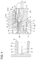
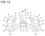
- FIGS. 1 to 13 One embodiment of the present invention is described with reference to FIGS. 1 to 13 .
- This embodiment includes first and second housings 10, 90 connectable to each other, a slider 60 to be assembled with the first housing 10, spring members 80 to be assembled with the slider 60, first terminal fittings 20 to be mounted into the first housing 10 and second terminal fittings 99 to be mounted into the second housing 90.
- connection surface sides of the first and second housings 10, 90 are referred to as front sides concerning a front-back direction and a vertical direction is based on FIG. 1 .
- the second housing 90 is made of synthetic resin and includes, as shown in FIG. 1 , a tubular receptacle 91. Tabs 95 of the second terminal fittings 99 are arranged to project into the receptacle 91. A lock portion 92 is provided to project on the upper surface of the upper wall of the receptacle 91. Further, as shown in FIG. 6 , a pair of guide projections 93 are formed to extend in the front-back direction at opposite widthwise sides of the lock portion 92 on the upper surface of the upper wall of the receptacle 91 and, further, a pair of pressing portions 94 are formed to extend in the front-back direction at opposite outer sides of the both guide projections 93. As shown in FIG. 4 , a releasing portion 96 capable of releasing locking between a resilient stopper 76 and a stopper receiving portion 25 to be described later is formed on the opening edge of the front end of the upper wall of the receptacle 91.
- the first housing 10 is likewise made of synthetic resin and includes, as shown in FIGS. 1 and 8 , a block-like housing main body 11 and a tubular fitting tube portion 12 surrounding the housing main body 11.
- a connection space 13 into which the receptacle 91 is fittable is formed to be open forward between the housing main body 11 and the fitting tube portion 12.
- a plurality of cavities 14 are formed to penetrate through the housing main body 11 in the front-back direction.
- a pair of cavities 14 are arranged side by side and deflectable locking lances 15 are formed to project on the lower surfaces of the cavities 14.
- the first terminal fitting 20 is inserted into each cavity 14. As shown in FIG.
- the first terminal fitting 20 is crimped and connected to a conductor part of a wire 100 and crimped and connected to a rubber plug 200 fitted on the wire 100.
- the first terminal fitting 20 is resiliently locked and retained by the locking lance 15, the rubber plug 200 is inserted into a rear end part of the cavity 14 to seal the interior of the cavity 14 in a liquid-tight manner and the wire 100 is drawn out from the rear end of the housing main body 11.
- a step 16 is formed on the outer peripheral surface of the housing main body 11 and a front area before the step 16 is slightly recessed from a rear area behind the step 16.
- a seal ring 300 is fitted before the step 16 on the outer peripheral surface of the housing main body 11.
- the receptacle 91 is inserted into the connection space 13 and the seal ring 300 is resiliently compressed between the receptacle 91 and the housing main body 11 at the time of connecting the first and second housings 10, 90, thereby sealing between the first and second housings 10, 90 in a liquid-tight manner.
- a cap-like front member 400 is mounted on a front end part of the outer peripheral surface of the housing main body 11.
- the above seal ring 300 is prevented from coming out forward by the front member 400.
- a lock arm 17 is coupled to the upper end of the outer peripheral surface of the housing main body 11 as shown in FIG. 1 .
- the lock arm 17 includes an arm supporting point portion 18 standing upward from the outer peripheral surface of the housing main body 11 and an arm main body 19 extending both forward and backward from the upper end of the arm supporting point portion 18.
- a lock projection 21 is formed to project downward on a front end part of the arm main body 19 and a releasing portion 22 is formed to be slightly higher on a rear end part of the arm main body 19.
- a recess 41 is formed at a position on the side of the arm supporting point portion 18 on the lower surface of the arm main body 19.
- the recess 41 is a shallow recess extending in the front-back direction and open on the rear end, and has a flat bottom surface with which a protrusion 57 to be described later can come into contact.
- the lock projection 21 interferes with the lock portion 92 and the arm main body 19 is deflected and deformed with the arm supporting point portion 18 as a supporting point in the process of connecting the first and second housings 10, 90.
- the arm main body 19 resiliently returns, the lock projection 21 is arranged to be able to lock the lock portion 92 and the first and second housings 10, 90 are held in a connected state.
- the releasing portion 22 is pushed down toward a deflection space 42 (see FIG. 1 ) located therebelow to separate the lock projection 21 from the lock portion 92 with the slider 60 pushed forward and retracted from the deflection space 42, whereby the first and second housings 10, 90 can be pulled apart from each other.
- a retaining portion 23 for regulating a backward detachment of the slider 60 is formed on a front end part of the upper surface of the arm main body 19.
- the retaining portion 23 is in the form of a rib extending in a width direction.
- a through hole 24 is formed in a widthwise central part of the arm supporting point portion 18.
- the stopper receiving portion 25 stepped from the upper surface of the housing main body 11 is formed below the through hole 24 on the arm supporting point portion 18 and behind the step 16.
- the later-described resilient stopper 76 of the slider 60 can pass through the through hole 24 and, as shown in FIG. 1 , a later-described locking projection 77 formed on a tip portion 51 of the resilient stopper 76 passed through the through hole 24 is lockable to the stopper receiving portion 25.
- the upper wall of the fitting tube portion 12 includes a pair of guide walls 26 at opposite sides of the lock arm 17.
- the both guide walls 26 extend backward from the front end of the housing main body 11 and a guide space 27 for guiding a movement of the slider 60 is formed by the both guide walls 26 and the housing main body 11.
- Rear parts of the both guide walls 26 have a substantially quarter-circular arcuate cross-section open upward and project further backward than the rear end of the housing main body 11. Front parts of the both guide walls 26 have a substantially quarter-circular arcuate cross-section open on a side facing the lock arm 17. As shown in FIGS. 8 and 9 , a pair of guide ribs 31 are formed to stand on the front parts of the both guide walls 26. The both guide ribs 31 extend in the front-back direction along the inner edges of the both guide walls 26 and are arranged at positions facing opposite widthwise ends of a front part of the arm main body 19.
- a pair of stopper walls 32 for closing a front side of the guide space 27 are formed to protrude on the front ends of the both guide walls 26.
- a pair of inner guide walls (not shown) are formed to extend backward on the lower ends of the both stopper walls 32.
- the inner guide walls are arranged substantially parallel to the guide walls 26. Front parts of later-described spring accommodating portions 65 of the slider 60 are guidably inserted between the inner guide walls and the guide walls 26. Further, the front ends of the spring accommodating portions 65 of the slider 60 come into contact with the stopper walls 32, thereby regulating any further forward movement of the slider 60.
- the slider 60 is described.
- the slider 60 is inserted into the guide space 27 of the first housing 10 and assembled with the first housing 10 movably in the front-back direction between an advanced position (position shown in FIGS. 1 to 4, 6 and 8 ) and a retracted position (position shown in FIGS. 5 and 7 ) while sliding on the guide walls 26.
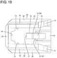
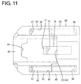
- the slider 60 is made of synthetic resin and includes a base portion 61 in the form of a plate piece extending along the width direction, a pair of arm portions 62 extending forward from opposite widthwise ends of the base portion 61 and a coupling portion 63 bridged between the front ends of the both arm portions 62 as shown in FIGS. 10 to 13 .
- the coupling portion 63 is located above the base portion 61 and arranged in an offset manner so as not to overlap the base portion 61 in a front view as shown in FIG. 13 . Further, as shown in FIG. 10 , a retaining/receiving portion 64 substantially in the form of a rectangular recess is formed in a widthwise central part of the rear end of the coupling portion 63. As shown in FIG. 7 , when the slider 60 is at the retracted position, the retaining portion 23 of the lock arm 17 is inserted into the retaining/receiving portion 64 to rest thereon.
- the spring accommodating portions 65 capable of accommodating the spring members 80 are formed below the both arm portions 62.
- the spring member 80 is formed by a known spring such as a compression coil spring and resiliently expandable and contractible in the front-back direction.
- the spring accommodating portion 65 is formed into a substantially hollow cylindrical shape and the spring member 80 can be entirely accommodated therein.
- the spring accommodating portion 65 includes first and second spring receiving portions 67, 68 on front and rear sides for receiving and supporting opposite front and rear ends of the spring member 80.
- the first and second spring receiving portions 67, 68 are arranged at positions not overlapping each other in a front view in consideration of the removal of a forming mold for the slider 60 in the front-back direction.
- an opening portion 66 open inward and downward is formed in a front part of the spring accommodating portion 65.
- the spring member 80 When the spring member 80 is mounted into the spring accommodating portion 65 as shown in FIG. 8 , a lower part of the front end of the spring member 80 is arranged in an exposed manner below the first spring receiving portion 67. This causes the pressing portions 94 of the second housing 90 to be introduced into the opening portions 66 while pushing the lower parts of the front ends of the spring members 80 in the process of connecting the first and second housings 10, 90. Further, the second spring receiving portion 68 can receive a spring force of the spring member 80 by coming into contact with the lower part of the front end of the spring member 80.
- the both arm portions 62 are formed with a pair of protection walls 73 standing substantially vertically upward from the spring accommodating portions 65.
- the both protection walls 73 are located to cover opposite widthwise ends of the lock arm 17.
- a pair of guide main bodies 74 capable of guiding a movement of the slider 60 are formed on upper end parts of the both arm portions 62.
- the guiding main bodies 74 have such a substantially arcuate cross-section as to protrude outwardly from the upper ends of the both protection walls 73 and then hang downwardly.
- push-in portions 75 inclined upwardly in a step-like manner from the rear end toward a front side are formed on the rear ends of the both arm portions 62.
- the push-in portions 75 are pressed forward, whereby the slider 60 can be moved toward the advanced position.
- the resilient stopper 76 capable of regulating a movement of the slider 60 to the retracted position is deflectably formed on the base portion 61.
- the resilient stopper 76 is cantilevered forward from a widthwise central part of the upper surface of the base portion 61.
- the locking projection 77 is formed to project downward on the tip portion 51 (front end part) of the resilient stopper 76.
- the locking projection 77 is hooked and locked to the stopper receiving portion 25 when the slider 60 is at the advanced position.
- an inclined surface 53 inclined obliquely downwardly is formed on the front surface of the tip portion 51 of the resilient stopper 76.
- a base end portion 52 of the resilient stopper 76 is formed as a first supporting point portion 54 integrally coupled to the widthwise central part of the upper surface of the base portion 61 and serves as an initial supporting point of deflection when the resilient stopper 76 starts to be deflected in the process of connecting the first and second housings 10, 90 as described later.
- the resilient stopper 76 includes a base-like thickened portion 78 formed by gradually increasing a thickness of an upper part from the base end portion 52 (first supporting point portion 54) to a substantially central area in the front-back direction.
- the upper surface of the thickened portion 78 has a flat surface 55 arranged substantially horizontally and a slant 56 inclined downwardly toward the front from the front end of the flat surface 55 when the resilient stopper 76 is in a natural state.
- the protrusion 57 is provided to project on a boundary part between the flat surface 55 and the slant 56 on the upper surface of the thickened portion 78 of the resilient stopper 76.
- the protrusion 57 is in the form of a rib extending in the width direction on the upper surface of the resilient stopper 76 as shown in FIG. 10 and has a substantially semicircular cross-section as shown in FIG. 12 . As shown in FIG. 12 ,
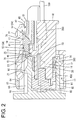
- the protrusion 57 comes into contact with the bottom surface of the recess 41 located near an arm supporting point of the lock arm 17 immediately before the first and second housings 10, 90 are properly connected and this contact position forms a supporting point of deflection of the resilient stopper 76 as a second supporting point portion 58 instead of the first supporting point portion 54.
- the structure of the connector of this embodiment is as described above. Next, an assembling method and a connecting operation of the connector are described.
- the spring members 80 are accommodated into the spring accommodating portions 65 of the slider 60.
- the spring members 80 are inserted into the spring accommodating portions 65 through the opening portions 66.
- the front ends of the spring members 80 are supported on the first spring receiving portions 67 and the rear ends of the spring members 80 are supported on the second spring receiving portions 68.
- the slider 60 is inserted into the guide space 27 of the first housing 10 from behind.
- the base portion 61 is located in the deflection space 42 below the releasing portion 22 of the lock arm 17, the protection walls 73 enter clearances between the guide walls 26 and the lock arm 17, and the coupling portion 63 is located above the arm main body 19.
- the resilient stopper 76 passes through the through hole 24 and, as shown in FIG. 1 , the locking projection 77 is arranged to be lockable to the stopper receiving portion 25 to prevent a backward detachment of the slider 60.
- the front ends of the spring accommodating portions 65 are arranged to be able to come into contact with the stopper walls 32 to regulate a forward displacement of the slider 60. In this way, the slider 60 is held at the advanced position with respect to the first housing 10 with forward and backward movements thereof regulated.
- the front and rear ends of the spring members 80 are supported on the first and second spring receiving portions 67, 68 when the slider 60 is at the advanced position. Further, at the advanced position, the protrusion 57 is located before the releasing portion 22 of the lock arm 17, thereby enabling the deflection of the lock arm 17.
- the receptacle 91 of the second housing 90 is fitted into the connection space 13 of the first housing 10.
- the pressing portions 94 of the second housing 90 enter the spring accommodating portions 65 to come into contact with the lower parts of the front ends of the spring members 80.
- the front ends of the spring members 80 are pressed by the pressing portions 94 to be separated from the first spring receiving portions 67 and the spring members 80 are resiliently compressed while being supported on the second spring receiving portions 68.
- the spring members 80 accumulate their spring forces while applying the spring forces to the slider 60.
- the releasing portion 96 of the second housing 90 comes into contact with the tip portion 51 of the resilient stopper 76 and slides on the inclined surface 53 in a final stage of the connecting process of the first and second housings 10, 90 and, associated with that, the resilient stopper 76 is deflected and deformed with the first supporting point portion 54 as a supporting point.
- the protrusion 57 is separated from the arm main body of the lock arm 17 and the entire resilient stopper 76 is not in contact with the lock arm 17.
- the protrusion 57 comes into contact with the bottom surface of the recess 41 of the lock arm 17 as shown in FIG. 3 .
- the resilient stopper 76 is deflected and deformed with the second supporting point portion 58 at this contact position as a supporting point as shown in FIG. 4 . That is, the supporting point of deflection of the resilient stopper 76 transitions from the first supporting point portion 54 to the second supporting point portion 58.
- a reaction force of the resilient stopper 76 is larger than when the first supporting point portion 54 functions as a supporting point while the second supporting point portion 58 functions as a supporting point.
- the protrusion 57 is substantially not affected by the deflection of the lock arm 17. That is, since the protrusion 57 is in contact with a part of the lock arm 17 which is substantially not deflected or deformed, the set position of the second supporting point portion 58 is precisely defined. Note that as the connection of the first and second housings 10, 90 progresses and the supporting point of deflection of the resilient stopper 76 transitions from the first supporting point portion 54 to the second supporting point portion 58, a locking margin between the locking projection 77 of the resilient stopper 76 and the stopper receiving portion 25 gradually decreases.
- first and second housings 10, 90 reach the proper connection position, locking between the locking projection 77 of the resilient stopper 76 and the stopper receiving portion 25 is released. Associated with that, the spring forces accumulated in the spring members 80 are released and the spring members 80 are going to return to a natural state. According to such returning movements of the spring members 80, the second spring receiving portions 68 of the slider 60 are pressed by the spring members 80 and the entire slider 60 is moved backward.
- the spring accommodating portions 65 slide on the inner surfaces of the guide walls 26 and the guide ribs 31 slide on the protection walls 73 and the guiding main bodies 74, thereby guiding the movement of the slider 60.
- the spring members 80 substantially return to the natural state and the retaining portion 23 of the lock arm 17 comes into contact with the retaining/receiving portion 64 of the slider 60, thereby regulating any further retracting movement of the slider 60.
- the protrusion 57 is located in the deflection space 42 on the side of the releasing portion 22 of the lock arm 17 and arranged in proximity to the lower surface of the lock arm 17 on the side of the releasing portion 22 as shown in FIG. 5 . Even if an external matter (including a finger) accidentally comes into contact with the releasing portion 22 of the lock arm 17 from above in this state, the lock arm 17 comes into contact with the protrusion 57, whereby any further deflection is regulated and the releasing portion 22 is not inadvertently operated for unlocking.
- the push-in portions 75 of the slider 60 are first pressed with fingers to push the slider 60 forward. Then, the spring members 80 are resiliently compressed and the pressing portions 94 are pressed by the spring members 80. As the slider 60 moves forward, the protrusion 57 is retracted from its position below the releasing portion 22 and the deflection of the lock arm 17 is permitted. If the releasing portion 22 is pressed to lift up the front end part of the lock arm 17 in that state, the lock projection 21 is separated from the lock portion 92. As the locking state of the lock arm 17 is released in this way, the spring members 80 press the pressing portions 94 forward and the first housing 10 is separated from the second housing 90 by those pressing forces (spring forces).
- the resilient stopper 76 includes the first and second supporting point portions 54, 58, the first supporting point portion 54 is configured on the base end portion 52 of the resilient stopper 76 and the second supporting point portion 58 is configured by the protrusion 57 formed closer to the tip side than the base end portion 52 of the resilient stopper 76.
- the reaction force of the resilient stopper 76 is larger than when the supporting point of deflection of the resilient stopper 76 is configured only by the first supporting point portion 54 since the resilient stopper 76 includes the second supporting point portion 58.
- the enlargement of the resilient stopper 76 cannot be avoided if the supporting point of deflection of the resilient stopper 76 is configured only by the second supporting point portion 58.
- the supporting point of deflection of the resilient stopper 76 is configured by both the first supporting point portion 54 and the second supporting point portion 58.
- the resilient stopper 76 needs not be enlarged in a part where the first supporting point portion 54 is caused to function. Therefore, the entire resilient stopper 76 needs not be enlarged and, consequently, the enlargement of the connector can be avoided.
- the second supporting point portion 58 is configured by the protrusion 57, the structure of the resilient stopper 76 does not become particularly complicated. Further, in the process of connecting the first and second housings 10, 90, the protrusion 57 is separated from the lock arm 17 except immediately before the properly connected state is reached. Thus, an increase of connection resistance is suppressed and operability at the time of connector connection can be improved.
- the protrusion 57 comes into contact with the lock arm 17 at the position near the arm supporting point portion 18 in configuring the second supporting point portion 58, a positional variation of the lock arm 17 can be small and the second supporting point portion 58 can be easily formed as compared with the case where the protrusion 57 comes into contact with the lock arm 17 at the position distant from the arm supporting point portion 18.
Landscapes
- Details Of Connecting Devices For Male And Female Coupling (AREA)
Applications Claiming Priority (1)
| Application Number | Priority Date | Filing Date | Title |
|---|---|---|---|
| PCT/JP2013/062975 WO2014181414A1 (fr) | 2013-05-08 | 2013-05-08 | Connecteur |
Publications (2)
| Publication Number | Publication Date |
|---|---|
| EP2996206A1 true EP2996206A1 (fr) | 2016-03-16 |
| EP2996206A4 EP2996206A4 (fr) | 2016-04-20 |
Family
ID=51866918
Family Applications (1)
| Application Number | Title | Priority Date | Filing Date |
|---|---|---|---|
| EP13883926.1A Withdrawn EP2996206A4 (fr) | 2013-05-08 | 2013-05-08 | Connecteur |
Country Status (6)
| Country | Link |
|---|---|
| US (1) | US9515410B2 (fr) |
| EP (1) | EP2996206A4 (fr) |
| JP (1) | JP5863083B2 (fr) |
| KR (1) | KR101795202B1 (fr) |
| CN (1) | CN105191009B (fr) |
| WO (1) | WO2014181414A1 (fr) |
Families Citing this family (19)
| Publication number | Priority date | Publication date | Assignee | Title |
|---|---|---|---|---|
| CN105191010B (zh) * | 2013-05-08 | 2017-08-25 | 住友电装株式会社 | 连接器 |
| JP6015854B2 (ja) * | 2013-05-08 | 2016-11-02 | 住友電装株式会社 | コネクタ |
| JP6326008B2 (ja) * | 2015-06-12 | 2018-05-16 | 矢崎総業株式会社 | コネクタ構造 |
| JP6254982B2 (ja) * | 2015-09-09 | 2017-12-27 | 矢崎総業株式会社 | コネクタ |
| JP6523221B2 (ja) | 2016-07-29 | 2019-05-29 | 矢崎総業株式会社 | コネクタ |
| JP6417370B2 (ja) * | 2016-07-29 | 2018-11-07 | 矢崎総業株式会社 | コネクタ |
| JP6417369B2 (ja) * | 2016-07-29 | 2018-11-07 | 矢崎総業株式会社 | コネクタ |
| JP6769354B2 (ja) * | 2017-03-13 | 2020-10-14 | 株式会社オートネットワーク技術研究所 | 端子ユニット及びコネクタ |
| US10283904B2 (en) * | 2017-08-04 | 2019-05-07 | Yazaki Corporation | Connector |
| CN111066207B (zh) * | 2017-08-31 | 2021-04-23 | 矢崎总业株式会社 | 部件锁定结构 |
| CN109616829B (zh) * | 2017-10-04 | 2020-04-24 | 矢崎总业株式会社 | 连接器 |
| CN111448720B (zh) * | 2017-12-26 | 2021-12-07 | 住友电装株式会社 | 连接器 |
| JP2020047363A (ja) * | 2018-09-14 | 2020-03-26 | 住友電装株式会社 | コネクタ |
| JP6786568B2 (ja) * | 2018-10-26 | 2020-11-18 | 矢崎総業株式会社 | 嵌合コネクタ |
| JP7226196B2 (ja) * | 2019-08-30 | 2023-02-21 | 株式会社オートネットワーク技術研究所 | コネクタ |
| JP7414635B2 (ja) * | 2020-05-07 | 2024-01-16 | 日本航空電子工業株式会社 | コネクタ組立体 |
| JP7111770B2 (ja) * | 2020-05-29 | 2022-08-02 | 矢崎総業株式会社 | コネクタのロック構造 |
| JP7380485B2 (ja) * | 2020-08-27 | 2023-11-15 | 住友電装株式会社 | コネクタ |
| KR102440790B1 (ko) * | 2021-02-26 | 2022-09-07 | 주식회사 경신 | 커넥터 |
Family Cites Families (15)
| Publication number | Priority date | Publication date | Assignee | Title |
|---|---|---|---|---|
| JP3427743B2 (ja) | 1998-08-20 | 2003-07-22 | 住友電装株式会社 | 嵌合検知コネクタ |
| JP3427745B2 (ja) | 1998-08-28 | 2003-07-22 | 住友電装株式会社 | 嵌合検知コネクタ |
| WO2000038279A1 (fr) * | 1998-12-18 | 2000-06-29 | Ryosei Electro-Circuit Systems, Ltd. | Connecteur electrique |
| JP2001085111A (ja) * | 1999-09-10 | 2001-03-30 | Sumitomo Wiring Syst Ltd | コネクタ |
| JP3841389B2 (ja) | 2000-02-25 | 2006-11-01 | 矢崎総業株式会社 | コネクタ嵌合構造 |
| JP4103333B2 (ja) * | 2000-12-28 | 2008-06-18 | 住友電装株式会社 | コネクタ及びコネクタにおける導通検査方法 |
| US20020155746A1 (en) * | 2001-04-19 | 2002-10-24 | Simpson Jeffrey S. | Cable assembly latch |
| JP4089179B2 (ja) * | 2001-06-06 | 2008-05-28 | 住友電装株式会社 | コネクタ |
| JP3887692B2 (ja) * | 2001-08-09 | 2007-02-28 | 住友電装株式会社 | コネクタ |
| JP2003142209A (ja) * | 2001-11-07 | 2003-05-16 | Sumitomo Wiring Syst Ltd | コネクタ |
| JP2003264031A (ja) * | 2002-03-07 | 2003-09-19 | Sumitomo Wiring Syst Ltd | 防水コネクタ |
| JP4306573B2 (ja) * | 2004-09-17 | 2009-08-05 | 住友電装株式会社 | コネクタ |
| JP4419875B2 (ja) | 2005-03-14 | 2010-02-24 | 住友電装株式会社 | 嵌合検知コネクタ |
| US7326074B1 (en) * | 2006-12-06 | 2008-02-05 | J.S.T. Corporation | Connector position assurance device and a connector assembly incorporating the connector position assurance device |
| JP5050820B2 (ja) | 2007-12-05 | 2012-10-17 | 住友電装株式会社 | コネクタ |
-
2013
- 2013-05-08 WO PCT/JP2013/062975 patent/WO2014181414A1/fr not_active Ceased
- 2013-05-08 EP EP13883926.1A patent/EP2996206A4/fr not_active Withdrawn
- 2013-05-08 KR KR1020157031503A patent/KR101795202B1/ko active Active
- 2013-05-08 US US14/787,010 patent/US9515410B2/en active Active
- 2013-05-08 CN CN201380076441.3A patent/CN105191009B/zh active Active
- 2013-05-08 JP JP2015515684A patent/JP5863083B2/ja not_active Expired - Fee Related
Also Published As
| Publication number | Publication date |
|---|---|
| JPWO2014181414A1 (ja) | 2017-02-23 |
| KR101795202B1 (ko) | 2017-11-07 |
| US9515410B2 (en) | 2016-12-06 |
| CN105191009A (zh) | 2015-12-23 |
| WO2014181414A1 (fr) | 2014-11-13 |
| EP2996206A4 (fr) | 2016-04-20 |
| JP5863083B2 (ja) | 2016-02-16 |
| KR20150138350A (ko) | 2015-12-09 |
| CN105191009B (zh) | 2017-12-15 |
| US20160104965A1 (en) | 2016-04-14 |
Similar Documents
| Publication | Publication Date | Title |
|---|---|---|
| US9515410B2 (en) | Connector with a slider releasably locked to a housing by a resilient stopper having two points of support for resilient deflection | |
| EP2996207A1 (fr) | Connecteur | |
| US9543702B2 (en) | Connector | |
| EP2637261B1 (fr) | Connecteur, ensemble connecteur et procédé d'assemblage de celui-ci | |
| EP2637262A1 (fr) | Connecteur, ensemble connecteur et son procédé d'assemblage/désassemblage | |
| EP2637260A1 (fr) | Connecteur, ensemble connecteur et procédé d'assemblage de celui-ci | |
| US11056831B2 (en) | Connector | |
| US9543687B2 (en) | Connector | |
| EP2913900B1 (fr) | Connecteur et procédé de connexion | |
| US20160123361A1 (en) | Connector | |
| US20220376425A1 (en) | Connector | |
| JP2014207070A (ja) | コネクタ | |
| KR101723327B1 (ko) | 커넥터 | |
| EP3139451A1 (fr) | Connecteur, ensemble connecteur et son procédé d'assemblage | |
| KR101788931B1 (ko) | 커넥터 | |
| KR101746968B1 (ko) | 커넥터 | |
| KR101805990B1 (ko) | 커넥터 | |
| JP2013200946A (ja) | コネクタ | |
| KR101810296B1 (ko) | 커넥터 | |
| KR101799098B1 (ko) | 홀더가 구비된 커넥터 | |
| JP2013093128A (ja) | コネクタ | |
| KR20160076440A (ko) | 커넥터 |
Legal Events
| Date | Code | Title | Description |
|---|---|---|---|
| PUAI | Public reference made under article 153(3) epc to a published international application that has entered the european phase |
Free format text: ORIGINAL CODE: 0009012 |
|
| 17P | Request for examination filed |
Effective date: 20151022 |
|
| AK | Designated contracting states |
Kind code of ref document: A1 Designated state(s): AL AT BE BG CH CY CZ DE DK EE ES FI FR GB GR HR HU IE IS IT LI LT LU LV MC MK MT NL NO PL PT RO RS SE SI SK SM TR |
|
| AX | Request for extension of the european patent |
Extension state: BA ME |
|
| A4 | Supplementary search report drawn up and despatched |
Effective date: 20160317 |
|
| RIC1 | Information provided on ipc code assigned before grant |
Ipc: H01R 13/641 20060101ALI20160311BHEP Ipc: H01R 13/639 20060101AFI20160311BHEP |
|
| DAX | Request for extension of the european patent (deleted) | ||
| 17Q | First examination report despatched |
Effective date: 20170830 |
|
| STAA | Information on the status of an ep patent application or granted ep patent |
Free format text: STATUS: THE APPLICATION IS DEEMED TO BE WITHDRAWN |
|
| 18D | Application deemed to be withdrawn |
Effective date: 20180110 |