EP2996378B1 - Procédé de mesure de qualité de communication - Google Patents
Procédé de mesure de qualité de communication Download PDFInfo
- Publication number
- EP2996378B1 EP2996378B1 EP13887171.0A EP13887171A EP2996378B1 EP 2996378 B1 EP2996378 B1 EP 2996378B1 EP 13887171 A EP13887171 A EP 13887171A EP 2996378 B1 EP2996378 B1 EP 2996378B1
- Authority
- EP
- European Patent Office
- Prior art keywords
- reference signal
- port
- information
- power
- port group
- Prior art date
- Legal status (The legal status is an assumption and is not a legal conclusion. Google has not performed a legal analysis and makes no representation as to the accuracy of the status listed.)
- Active
Links
Images


Classifications
-
- H—ELECTRICITY
- H04—ELECTRIC COMMUNICATION TECHNIQUE
- H04L—TRANSMISSION OF DIGITAL INFORMATION, e.g. TELEGRAPHIC COMMUNICATION
- H04L5/00—Arrangements affording multiple use of the transmission path
- H04L5/003—Arrangements for allocating sub-channels of the transmission path
- H04L5/0048—Allocation of pilot signals, i.e. of signals known to the receiver
-
- H—ELECTRICITY
- H04—ELECTRIC COMMUNICATION TECHNIQUE
- H04W—WIRELESS COMMUNICATION NETWORKS
- H04W24/00—Supervisory, monitoring or testing arrangements
-
- H—ELECTRICITY
- H04—ELECTRIC COMMUNICATION TECHNIQUE
- H04B—TRANSMISSION
- H04B17/00—Monitoring; Testing
- H04B17/30—Monitoring; Testing of propagation channels
- H04B17/309—Measuring or estimating channel quality parameters
- H04B17/347—Path loss
-
- H—ELECTRICITY
- H04—ELECTRIC COMMUNICATION TECHNIQUE
- H04L—TRANSMISSION OF DIGITAL INFORMATION, e.g. TELEGRAPHIC COMMUNICATION
- H04L1/00—Arrangements for detecting or preventing errors in the information received
- H04L1/0001—Systems modifying transmission characteristics according to link quality, e.g. power backoff
- H04L1/0023—Systems modifying transmission characteristics according to link quality, e.g. power backoff characterised by the signalling
- H04L1/0026—Transmission of channel quality indication
-
- H—ELECTRICITY
- H04—ELECTRIC COMMUNICATION TECHNIQUE
- H04L—TRANSMISSION OF DIGITAL INFORMATION, e.g. TELEGRAPHIC COMMUNICATION
- H04L5/00—Arrangements affording multiple use of the transmission path
- H04L5/0001—Arrangements for dividing the transmission path
- H04L5/0014—Three-dimensional division
- H04L5/0023—Time-frequency-space
Definitions
- the present invention relates to the field of communications technologies, and in particular, to a method and an apparatus for measuring communication quality.
- signals may usually be classified into two types: one type of signal carries information from a higher layer; the other type of signal does not carry information from a higher layer, and this type of signal is usually used for assisting in or indicating reception of the former type of signal.
- a transmit power of a signal is a very important parameter for both types of signals above.
- a power of a reference signal may be used for deriving a path loss estimation value, and the path loss estimation value may be used as a part of open-loop control to implement uplink power control, or may be used as a basis for selecting a cell (or a transmit node, or a receive node).
- a power ratio of a physical downlink shared channel (PDSCH) signal to a reference signal may be used for deriving channel state information (CSI), thereby facilitating implementation of scheduling and link adaptation.
- a reference signal for example, a cell-specific reference signal (CRS) or a channel state information reference signal (CSI-RS)
- CSI channel state information
- a power-related parameter is determined on a base station side or a network side, and is notified to user equipment (UE) by using higher layer signaling.
- UE user equipment
- a conventional base station antenna configuration has a fixed downtilt, and an uplink and a downlink undergo similar path losses, so that a downlink path loss can be desirably used for estimating an uplink path loss. Therefore, distinguishing of antenna ports can be omitted in the power-related parameter sent by the base station side or the network side, and especially in a case of multiple antenna ports. If antenna ports are not distinguished, a downlink path loss can be desirably used for estimating an uplink path loss.
- a reference signal received power (RSRP), of a current cell/node or an adjacent cell/node, reported by user equipment (UE) may be used by a base station or an evolved node B (eNB) to select a serving cell or node for the UE.
- RSRP is an estimation obtained by performing averaging on different antenna ports.
- an AAS active antenna systems
- the LTE R12 standard that is about to be launched is considering enhancement of communication performance after introduction of an AAS system.
- an AAS further provides design flexibility in a vertical direction of an antenna, where independent downtilts may be used in an uplink and a downlink, and powers of different antenna ports may be different.
- antenna array structures of the AAS base stations may also be different. Therefore, antenna ports having a same sequence number may also have different transmit powers in different array structures.
- US 2012/176939 A1 discloses a communications system and a method for performing communications, wherein User Equipments (UEs) are provided with UE-specific configuration information, such as CSI-RS (Channel Status Indication-Reference Signal) patterns, antenna port groupings, reference signal configurations, subframe configurations, and/or scrambling codes.
- UE-specific configuration information such as CSI-RS (Channel Status Indication-Reference Signal) patterns, antenna port groupings, reference signal configurations, subframe configurations, and/or scrambling codes.
- CSI-RS Channel Status Indication-Reference Signal
- WO 2013/081368 A1 discloses a method and apparatus for transmitting a reference signal and discloses an uplink transmission method and apparatus using the same.
- the method of transmitting a reference signal in a Cooperative Multi-Point (CoMP) system includes sending configuration information on the reference signal and sending the reference signal based on the configuration information on the reference signal, wherein the configuration information on the reference signal indicates Energy Per Resource Element (EPRE), used to transmit the reference signal, for each of transmission points that participate in the transmission of the reference signal.
- CoMP Cooperative Multi-Point
- Embodiments of the present invention provide methods for measuring communication quality, thereby overcoming a problem in the prior art that accurate signal quality measurement information cannot be acquired in a multi-antenna system.
- An aspect provides a method for measuring communication quality, including:
- the reference signal power information of the at least two port groups includes:
- reference signal resource configuration information is sent to UE on a user side, and the UE may perform processing according to reference signal quality, of one port group or multiple port groups, in the reference signal resource configuration information to obtain final signal quality measurement information, so that a UE side can distinguish ports according to different port groups, which differs from a case in which transmit powers of different ports cannot be distinguished in the prior art. Therefore, UE is enabled to acquire signal quality measurement information, so that the UE can perform more accurate cell selection and uplink power control.
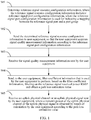
- An embodiment of the present invention provides a method for measuring communication quality. As shown in FIG. 1 , the method includes: Step S01: Determine reference signal resource configuration information, where the reference signal resource configuration information includes: reference signal port configuration information, where the reference signal port configuration information is used for indicating a mapping between the reference signal port and a port group.
- the operation may specifically be executed on a base station side or a network side (for example, a Universal Terrestrial Radio Access Network (UTRAN)), or an evolved UTRAN, or an evolved node B.
- UTRAN Universal Terrestrial Radio Access Network
- UTRAN Universal Terrestrial Radio Access Network
- the reference signal resource configuration information includes the reference signal port configuration information, and optionally, the reference signal resource configuration information may further include reference signal power information of at least one port group
- the reference signal resource configuration information is sent to user equipment (UE), so that the user equipment acquires signal quality measurement information according to the reference signal resource configuration information.
- UE user equipment
- the UE may perform processing according to reference signal quality, of one port group or multiple port groups, in the reference signal resource configuration information to obtain final signal quality measurement information, so that a UE side can distinguish ports according to different port groups, which differs from a case in which transmit powers of different ports cannot be distinguished in the prior art. Therefore, the signal quality measurement information acquired in the solution enables the UE to perform more accurate cell selection and uplink power control.
- the reference signal resource configuration information may further include: any one of a reference signal configuration and a reference signal subframe configuration. Therefore, the UE can receive a reference signal according to the information. It should be understood that, however, this embodiment of the present invention does not limit that any one of the reference signal configuration and the reference signal subframe configuration is necessarily delivered to the UE by using the reference signal resource configuration information, and may also be delivered to the UE in a form of other information. It should be pointed out that the reference signal configuration or the reference signal subframe configuration may also be predefined, or is implicitly derived according to a parameter, for example, a cell ID or a UE ID, that is known in advance, and is known to both a base station and the UE, which is not limited in this embodiment of the present invention.
- Step S02 Send the determined reference signal resource configuration information to user equipment, so that the user equipment acquires signal quality measurement information according to the reference signal port configuration information.
- the foregoing signal quality measurement information may include: any one or any combination of a reference signal received power RSRP, a reference signal received quality RSRQ, and a reference signal strength indicator RSSI.
- reference signal resource configuration information is determined on a network side, and the reference signal resource configuration information is sent to a user side, where the reference signal resource configuration information includes reference signal port configuration information, where the reference signal port configuration information is used for indicating a mapping between the reference signal port and a port group.
- reference signal power related information is indicated port by port, so as to reduce a signaling overhead; further, a uniform power indicator is used for ports in a port group, and for different port groups, power related information of the port groups may be indicated independently, so that full use of an antenna configuration or an antenna array structure is made, thereby enabling a system to flexibly select reference signal power related information according to the antenna configuration or the antenna array structure; because an antenna array may have symmetric weights, by means of the symmetry of the weights, design complexity in beamforming or side lobe suppression can be reduced.
- the reference signal resource configuration information is sent to UE on the user side, and the UE may perform processing according to reference signal quality of at least one port group in the reference signal resource configuration information to obtain final signal quality measurement information, so that a UE side can distinguish ports according to different port groups, which differs from a case in which transmit powers of different ports cannot be distinguished in the prior art.
- the UE is enabled to acquire signal quality measurement information, so that the UE can perform more accurate cell selection and uplink power control.
- the method further includes: Step S03: Receive the signal quality measurement information sent by the user equipment.
- the method further includes: Step S04: Send, to the user equipment, filter coefficient information that is used by the user equipment to perform, based on the filter coefficient information, filtering on the reference signal received power RSRP and obtain a path loss estimation value.
- the filter coefficient information may be sent to the user equipment at a same time when the determined reference signal resource configuration information is sent to the user equipment in step S02, for example, the filter coefficient information and the determined reference signal resource configuration information are sent in a same subframe; or may be sent before or after the determined reference signal resource configuration information is sent to the user equipment in step S02.
- the filter coefficient information and the reference signal resource configuration information may be sent in an information element (IE) of same or different higher layer signaling such as RRC signaling, or same or different downlink control information (DCI).
- IE information element
- the method further includes: Step S05: Receive an uplink physical channel or an uplink physical signal sent by the user equipment, where a transmit power of the uplink physical channel or the uplink physical signal is obtained by means of calculation by the user equipment according to the path loss estimation value.
- the reference signal resource configuration information further includes: reference signal power information of at least two port groups that is used by the user equipment to acquire the signal quality measurement information according to the reference signal port configuration information and in combination with the reference signal power information of the at least two port groups; and the reference signal power information of the at least two port groups includes:
- the reference signal port configuration information is a single index, or is a double index, or is an index after combined coding.
- the reference signal power information of the port group at least includes: reference signal powers of ports in one port group are the same.
- the first port group is one port group among the at least one port group.
- This embodiment of the present invention provides a method for measuring communication quality.
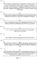
- the method includes: Step 101: Receive reference signal resource configuration information sent by a base station, where the reference signal resource configuration information includes reference signal port configuration information, where the reference signal port configuration information is used for indicating a mapping relationship between a reference signal port and a port group.
- UE receives the reference signal resource configuration information, which may be that the UE receives, by using higher layer signaling (for example, radio resource control (RRC) signaling) or dynamic signaling (for example, downlink control information (DCI), the reference signal resource configuration information notified by an eNB, or obtains, based on a cell identity (ID), the reference signal resource configuration information.
- the higher layer signaling may be sent by using a data channel such as a physical downlink shared channel (PDSCH for short).
- the dynamic signaling, for example, the DCI is sent by using a control channel such as a physical downlink control channel (PDCCH) or an enhanced PDCCH (ePDCCH).
- PDSCH physical downlink shared channel
- ePDCCH enhanced PDCCH
- the reference signal port configuration information is used for indicating a mapping between a reference signal port and a port group.
- the mapping relationship between a reference signal port and a port group may be predefined, and is known to both the base station and the user equipment. Therefore, a base station side and a user equipment side can both find the reference signal port configuration message by means of identification.
- a port included in the port group may be uniquely determined. As shown in Tables 1 to 3, after learning the information about the mapping relationship between a reference signal port group and a corresponding port, and the mapping index of the port group, a device can learn a port in the corresponding port group. Ports included in the port group may be predefined, and for a different index, a predefined port group may be obtained according to planning. It should be noted that one reference signal port corresponds to one antenna port, and one antenna port corresponds to one reference signal port. Channel information of an antenna signal port is obtained by means of measurement of a reference signal port. Therefore, usually the predefined port group may be obtained according to planning of an antenna port array configuration.
- One reference signal port or antenna port usually corresponds to one physical antenna or one virtual antenna, where the virtual antenna may be obtained by means of weighted combination of multiple physical antennas.
- An actual antenna deployment may have a different antenna configuration and antenna port array form.
- FIG. 3 shows different uniform linear array (ULA) antenna port array configurations.
- An antenna port array A is a 2-row 4-column uniform linear array
- an antenna port array B is a 2-row 8-column uniform linear array
- an antenna port array C is a 4-row 4-column uniform linear array.
- both the antenna port array B and the antenna port array C have 16 ports, array forms of the antenna port array B and the antenna port array C are also different.
- FIG. 4 shows different cross-polarization (XPO) antenna array configurations.
- An antenna port array A is a 2-row 2-column cross-polarization antenna array
- an antenna port array B is a 2-row 4-column uniform linear array
- an antenna port array C is a 4-row 2-column uniform linear array.
- Different polarization antennas may be located in a same column.
- both the antenna port array B and the antenna port array C have 16 ports, array forms of the antenna port array B and the antenna port array C are also different.
- the antenna port array is referred to as an antenna array for short below.
- the reference signal port configuration information includes a quantity of reference signal ports and a mapping index, where the mapping index is used for indicating a mapping between a reference signal port group and a corresponding port.
- 8-antenna arrays represented by the antenna array A shown in FIG. 3 and the antenna array A shown in FIG. 4 are used as examples.
- the reference signal port configuration information includes: a quantity of reference signal ports is 8 and a mapping index is 0 or 1.
- the predefined mapping relationship between a reference signal port and a port group may be defined by using a function, or may be regulated by using a predefined table. For example, as shown in Table 1, the first row may be the reference signal port configuration information of the antenna array A in FIG.
- the mapping indication information includes: a quantity of reference signal ports is 8, a mapping index is 0, and two port groups are a port group 0 and a port group 1.
- the second row in Table 1 may be the reference signal port configuration information of the antenna array A in FIG. 4 , and the mapping indication information includes: a quantity of reference signal ports is 8, a mapping index is 1, and two port groups are a port group 0 and a port group 1. It should be pointed out that, in this embodiment, a reference signal port and a reference signal port group may be interchangeable with an antenna port and an antenna port group.
- the port group 0 when a mapping index value is 0, the port group 0 includes reference signal ports (or antenna ports) 0, 3, 4, and 7, the port group 1 includes reference signal ports (or antenna ports) 1, 2, 5, and 6; when a mapping index value is 1, the port group 0 includes reference signal ports (or antenna ports) 0, 1, 4, and 5, the port group 1 includes reference signal ports (or antenna ports) 2, 3, 6, and 7.
- the reference signal port configuration information includes: a quantity of reference signal ports is 16, and a mapping index is 0 or 1 or 2 or 3.
- the predefined mapping relationship between a reference signal port and a port group may be defined by using a function, or may be regulated by using a predefined table, for example, as shown in Table 2: Table 2-Mapping between a port and a port group Index Mapping between a port and a port group 0 1 2 3 0 0, 3, 8, 11 4, 7, 12, 15 1, 2, 9, 10 5, 6, 13, 14 1 0, 1, 12, 13 2,3, 14, 15 4, 5, 8, 9 6, 7, 10, 11 2 0, 7, 8, 15 1, 6, 9, 14 2, 5, 10, 13 3, 4, 11, 12 3 0, 3, 12, 15 1,2, 13, 14 4, 7, 8, 11 5, 6, 9, 10
- a mapping index value is 0, a port group 0 includes reference signal ports (or antenna ports) 0, 3, 8, and 11, a port group 1 includes reference signal ports (or antenna ports) 4, 7, 12, and 15, a port group 2 includes reference signal ports (or antenna ports) 1, 2, 9, and 10, and a port group 3 includes reference signal ports (or antenna ports) 5, 6, 13, and 14.
- mapping index value is 1 or 2 or 3
- reference signal ports included in each port group may be sequentially obtained by analogy from the foregoing Table.
- the reference signal port configuration information may include a port group mapping double index (m, n).
- the predefined mapping relationship between a reference signal port and a port group may be defined by using a function, or may be regulated by using a predefined table, for example, as shown in Table 3: Table 3-Mapping between a port and a port group Double index (m, n) Mapping between a port and a port group 0 1 2 3 (2, 4) 0, 1, 4, 5 2, 3, 6, 7 - - (2, 8) 0, 3, 8, 11 4, 7, 12, 15 1, 2, 9, 10 6, 7, 10, 11 (4, 4) 0, 1, 12, 13 2, 3, 14, 15 4, 5, 8, 9 6, 7, 10, 11
- the double index (m, n) may indicate that a quantity of reference signal ports is a product of m and n.
- combined coding may be performed on the double index information.
- Table 3a-Mapping between a port and a port group Combined coding of a double index (m, n) Double index (m, n) Mapping between a port and a port group 0 1 2 3 0 (2, 4) 0, 1, 4, 5 2, 3, 6, 7 - - 1 (2, 8) 0, 3, 8, 11 4, 7, 12, 15 1, 2, 9, 10 6, 7, 10, 11 2 (4, 4) 0, 1, 12, 13 2, 3, 14, 15 4, 5, 8, 9 6, 7, 10, 11 or Table 3b-Mapping between a port and a port group Mapping index Double index (m, n) Mapping between a port and a port group 0 1 2 3 0 (2, 4) 0, 1, 4, 5 2, 3, 6, 7 - - 1 (2, 8) 0, 3, 8, 11 4, 7, 12, 15 1, 2, 9, 10 6, 7, 10, 11 2 (4, 4) 0, 1, 12, 13 2, 3, 14, 15 4, 5, 8, 9 6, 7, 10, 11 or Table 3b-Mapping between a port and a port group Mapping index Double index (m
- grouping of port groups may be that 4 reference signal ports (or antenna ports) are used as one port group.
- grouping of port groups may also be not limited to a port group including 4 reference signal ports, or may be a port group having 2 or 8 ports or in another formation.
- a number of a reference signal port included in each port group is also not limited to the foregoing value, and may be flexibly selected according to an actual antenna configuration or deployment.
- the foregoing predefined port group mapping and mapping indication information may enable a system to adapt to more antenna configurations and antenna array deployments.
- the reference signal resource configuration information may further include: any one of a reference signal configuration and a reference signal subframe configuration.
- the reference signal configuration may include: any one of a subcarrier used by a reference signal port, an orthogonal frequency division multiplexing (OFDM) symbol, and a code resource.
- the reference signal subframe configuration may include: any one of a subframe position occupied by a reference signal port, a subframe period, and a subframe offset.
- the reference signal configuration or the reference signal subframe configuration may also be predefined, or is implicitly derived according to a parameter, for example, a cell ID or a UE ID, that is known in advance, and is known to both the base station and the UE, which is not limited in this embodiment of the present invention.
- Step 102 Obtain reference signal port information in at least one port group according to the reference signal port configuration information.
- Step 103 Acquire signal quality measurement information according to the reference signal port information in the at least one port group.
- the reference signal or signal may specifically include a cell-specific reference signal CSR, or a channel state information reference signal (CSI-RS), or a demodulation reference signal (DMRS), but is not limited to current examples.
- CSR cell-specific reference signal
- CSI-RS channel state information reference signal
- DMRS demodulation reference signal
- the signal quality measurement information may be a reference signal received power (RSRP) or a reference signal received quality (RSRQ) or a reference signal strength indicator (RSSI), or may also be other signal quality measurement information defined based on a reference signal.
- RSRP reference signal received power
- RSSI reference signal received quality
- RSSI reference signal strength indicator
- a reference signal received power RSRP is used as an example and one implementation is described in detail.
- This solution is not limited to another implementation solution, and a solution of acquiring other signal quality measurement information is also not limited.
- the obtaining reference signal port information in at least one port group according to the reference signal port configuration information in step 102 may include:
- a mapping index in Table 2 is 0, and in this case, reference signal ports included in a port group 0 are 0, 3, 8, and 11.
- Complex RSRP measurement of each antenna port may be correlation between two adjacent reference signal resource elements (RE, Resource Element).
- the two adjacent REs herein may refer to two adjacent REs in a frequency domain, or two adjacent REs in a time domain, or two adjacent REs in a time-frequency domain.
- ⁇ p ( m ) is a channel estimation on a reference signal RE whose label number is m
- K s is a total sample quantity of usable reference signal REs in measurement bandwidth
- p is a number of a reference signal port in the one specified port group
- r is an index of a receive antenna.
- An RSRP corresponding to the antenna port group 0 may be obtained by combining (combine) RSRP ( r , p ).
- a reference signal received power RSRP ( r , p ) of a pth port of an rth receive antenna is obtained and the RSRP is obtained by combining RSRP ( r , p ).
- RSRP ( r , p ) linear (correlated or uncorrelated) averaging is performed on ports p and receive antennas, and then an absolute value is taken, to obtain the RSRP corresponding to the port group 0.
- linear (correlated or uncorrelated) averaging is performed on one port p and receive antennas, and then an absolute value is taken, to obtain the RSRP corresponding to the port group 0.
- the RSRP may also be obtained by using reference signals of another port group.
- the port group used for obtaining an RSRP and a port in the port group may be predefined (for example, the port group 0, and the port 0 in the port group 0, or the ports 0 and 3 in the port group 0, or all the ports in the port group 0, or others) or notified by a base station eNB by using higher layer signaling such as RRC signaling or by using downlink control information.
- an RSRP is obtained based on one port group or some or all ports in one port group, and RSRPs do not need to be measured port by port, so that implementation complexity in measuring an RSRP by UE can be reduced; at the same time, a port group is predefined or notified, so that the UE and the eNB have consistent understanding of measurement, thereby ensuring consistency in measurement of RSRPs.
- powers of the port groups may be independently indicated, and full use of antenna configurations and antenna array structures shown in FIG. 3 and FIG. 4 is made, so as to adapt to changes in an antenna structure to perform flexible indication, thereby ensuring that the base station eNB can adapt to multiple antenna configurations and antenna arrays.
- reference signal power information, of one or more port groups, included in the reference signal resource configuration information received by the UE in step 101 is used for indicating a reference signal power of ports in a corresponding port group.
- reference signal powers of 4 port groups may be shown in Table 4: Table 4-Table of reference signal powers of port groups Port group number 0 1 2 3 Reference signal power p0 p1 p2 p3
- a power of a reference signal port included in a port group 0 is p0
- powers of reference signal ports included in port groups 1, 2, and 3 may be sequentially obtained by analogy, which are respectively p1, p2, and p3.
- reference signal power information of the foregoing one or more port groups may also be jointly represented by using a reference signal power of one port group (for example, the port group 0) among the one or more port groups and a ratio of a reference signal power of another port group (for example, the port group 1) to the reference signal power of the port group (for example, the port group 0) or ratios of reference signal powers of multiple port groups (for example, the port groups 1, 2, and 3) to the reference signal power of the port group (for example, the port group 0).
- the reference signal power of the port group 0 is p0
- the ratios of the reference signal powers of the port groups 1, 2, and 3 to the reference signal power of the port group 0 are respectively ⁇ 1, ⁇ 2, and ⁇ 3.
- the UE may obtain that the reference signal powers of the port groups 1, 2, and 3 are respectively p0* ⁇ 1, p0* ⁇ 2, and p0* ⁇ 3.
- reference signal power information of the one or more port groups may also be represented by using a reference signal power of one port group (for example, the port group 0) among the one or more port groups and a differential between a reference signal power of another port group (for example, the port group 1) and the reference signal power of the port group (for example, the port group 0) or differentials between reference signal powers of multiple port groups (for example, the port groups 1, 2, and 3) and the reference signal power of the port group (for example, the port group 0).
- the reference signal power of the port group 0 is p0
- the differentials between the reference signal powers of the port groups 1, 2, and 3 and the reference signal power of the port group 0 are respectively d1, d2, and d3.
- the UE may obtain that the reference signal powers of the port groups 1, 2, and 3 are respectively p0+d1, p0+d2, and p0+d3.
- reference signal power information is separately indicated for port groups, and it can be avoided that reference signal powers are indicated port by port, so as to reduce a signaling overhead; further, a uniform power indicator is used for ports in a port group, and for different port groups, different port groups powers may be independently indicated, so that full use of an antenna configuration or an antenna array structure is made, thereby enabling a system to flexibly select a reference signal power according to the antenna configuration or the antenna array structure.
- grouping of port groups is not limited to a port group including 4 reference signal ports, and the grouping of port groups and the formation of the ports in Tables 1, 2, and 3 above may further enable the antenna arrays in FIG. 3 or FIG. 4 to have powers symmetric about array structures, that is, the ports may have symmetric weights relative to the array, and by means of the symmetry of the weights, design complexity in beamforming or side lobe suppression can be reduced.
- reference signal power above may also be represented by using an energy per resource element (EPRE).
- EPRE energy per resource element
- reference signal power information of at least two port groups includes:
- the foregoing acquiring the signal quality measurement information according to the reference signal port configuration information and in combination with the reference signal power information of the at least two port groups includes:
- the signal quality measurement information may be obtained by combining reference signal received powers of more than one port group.
- the reference signal resource configuration information received according to step 101 further includes: reference signal power information of at least two port groups that is used by the user equipment to acquire the signal quality measurement information according to the reference signal port configuration information and in combination with the reference signal power information of the at least two port groups.
- the performing, according to the reference signal power information of the at least two port groups, weighted averaging on the obtained signal quality measurement information corresponding to the at least two port groups in accordance with a port group power, to obtain the signal quality measurement information includes:
- the multiple port groups above may be all port groups, or may be some port groups. Therefore, preset port information may be information about all port groups, or may be information about some port groups.
- the some port groups may be agreed in advance (for example, the port group 0 and the port group 1) or notified by the base station eNB by using higher layer signaling such as RRC signaling or by using downlink control information.
- RSRPs of the multiple port groups are obtained, and processing such as smoothing or filtering may be performed on the RSRP obtained for each port group, so as to further increase precision of measuring an RSRP; at the same time, it is avoided that the UE performs calculation port by port, thereby lowering implementation complexity.
- a configuration of a port group can ensure that the base station eNB can adapt to multiple antenna configurations and antenna arrays.
- a reference signal sent by the base station is received, and the UE may further obtain signal quality measurement information, such as a reference signal received quality (RSRQ) or a reference signal strength indicator (RSSI), of one or more port groups.
- the RSSI is a received total wideband power, including a power of interference and a power of thermal noise
- the RSRQ is a ratio of an RSRP to the RSSI.
- the method for measuring communication quality may further include:
- Step 104 The UE reports, to a base station eNB, the channel quality measurement information, for example, an RSRP, so as to help implement cell selection or cell handover.
- the channel quality measurement information for example, an RSRP
- the method for measuring communication quality may further include: Step 105: Receive filter coefficient information sent by the base station.
- Step 106 Perform, based on the filter coefficient information, filtering on the reference signal received power RSRP, and obtain a path loss estimation value.
- the user equipment may receive filter coefficient information sent by the base station at the same time when the reference signal resource configuration information is received in step 101, for example, the filter coefficient information and the reference signal resource configuration information are received in a same subframe.
- the filter coefficient information sent by the base station may also be received before or after the reference signal resource configuration information is received in step 101.
- the filter coefficient information and the reference signal resource configuration information may be received in an information element (IE) of same or different higher layer signaling such as RRC signaling, or same or different downlink control information (DCI).
- IE information element
- PL ( g ) represents the PL estimation obtained based on the port group g, where a higher layer filtering parameter is notified by using higher layer signaling.
- a PL estimation may be obtained by using a PL of one port group, for example, the port group 0.
- the higher layer filtered RSRP of the port group g is obtained by performing filtering on the RSRP of the port group g by using the higher layer filter parameter notified by using the higher layer signaling.
- the foregoing port group for obtaining a PL estimation may be predefined (for example, the port group 0) or notified by the base station eNB by using higher layer signaling such as RRC signaling or by using downlink control information.
- a PL estimation is obtained above based on one port group, which can reduce implementation complexity of PL estimation by UE, and ensure consistency of PL estimation.
- a configuration of a port group can ensure that the base station eNB can adapt to multiple antenna configurations and antenna arrays.
- the path loss estimation may also be obtained based on reference signal received powers of multiple port groups and corresponding reference signal powers.
- the PL estimation may be a linear average of PL estimations obtained for the multiple port groups.
- the multiple port groups above may be all port groups, or may be some port groups.
- the some port groups may be agreed in advance (for example, the port group 0 and the port group 1) or notified by the base station eNB by using higher layer signaling such as RRC signaling or by using downlink control information.
- PL estimations are obtained for multiple port groups, which can further increase precision of PL estimation, and avoid excessively high complexity of implementation by UE.
- a configuration of a port group can ensure that the base station eNB can adapt to multiple antenna configurations and antenna arrays.
- the method for measuring communication quality may further include: Step 107: Send an uplink physical channel or an uplink physical signal to the base station, where a transmit power of the uplink physical channel or the uplink physical signal is obtained by means of calculation according to the path loss estimation value.
- the physical channel may be a physical uplink control channel PUCCH, a physical uplink shared channel PUSCH, or the like.
- the physical signal may be a sounding reference signal (SRS) or a demodulation reference signal (DMRS) that is used for the uplink physical channel.
- SRS sounding reference signal
- DMRS demodulation reference signal
- P CMAX,c ( i ) is a maximum transmit power configured on UE in a subframe i of a serving cell c
- P O_PUCCH is a parameter formed by the sum of a cell-specific parameter P O_NOMINAL_PUCCH provided by a higher layer and a UE specific parameter P O_UE_PUCCH .
- h ( n CQI , n HARQ , n SR ) is a value dependent on a PUCCH format, where n CQI corresponds to a quantity of information bits of a CQI.
- the parameter n HARQ is a quantity of HARQ-ACK bits sent in the subframe i.
- the parameter ⁇ F_PUCCH ( F ) is provided by a higher layer, and a value of each ⁇ F_PUCCH ( F ) corresponds to a PUCCH format (F).
- g ( i ) is a current PUCCH power control state of the UE.
- PL c is an estimation value, of a path loss, obtained for the cell C by the UE by using the method in step 104.
- P CMAX,c ( i ) is a maximum transmit power configured on UE in a subframe i of a serving cell c
- M PUSCH,c ( i ) is the bandwidth of the PUSCH resource assignment expressed in number of resource blocks valid for subframe i and serving cell c .
- ⁇ c ⁇ ⁇ 0,0.4,0.5,0.6,0.7,0.8,0.9,1 ⁇ is a 3-bit parameter, and is provided by a higher layer.
- ⁇ TF,c ( i ) is a parameter that is determined by using higher layer signaling and related to a transmission format.
- f c ( i ) is a current PUSCH power control adjustment state of the UE.
- PL c is an estimation value, of a path loss, obtained for the cell C by the UE by using the method in step 104.
- M SRS,c bandwidth of SRS transmission of a subframe i of the serving cell c .
- f c ( i ) is a current PUSCH power control adjustment state of the serving cell c .
- PL c is an estimation value, of a path loss, obtained for the cell C by the UE by using the method in step 104.
- the above path loss estimation is used for open-loop control of an uplink channel, which can further improve reliability of power control, and ensure that the base station eNB can adapt to multiple antenna configurations and antenna arrays.
- This embodiment of the present invention provides a method for measuring communication quality.
- the method includes: Step S21: Determine reference signal resource configuration information, and send the reference signal resource configuration information to user equipment, where the reference signal resource configuration information includes: reference signal port configuration information and power ratio information, where the reference signal port configuration information is used for indicating a mapping between the reference signal port and a port group, and the power ratio information is used for indicating a power ratio of a data channel of at least one port group to a reference signal.
- the reference signal resource configuration information includes: the reference signal port configuration information and the power ratio information
- the reference signal resource configuration information is sent to the user equipment (UE), so that the user equipment acquires channel state information CSI according to the reference signal resource configuration information.
- the UE may perform processing according to reference signal quality, of one port group or multiple port groups, in the reference signal resource configuration information to obtain final signal quality measurement information, so that a UE side can distinguish ports according to different port groups, which differs from a case in which transmit powers of different ports cannot be distinguished in the prior art. Therefore, channel state information acquired in the solution may enable the UE to perform more accurate modulation and coding scheme (MCS) selection or scheduling, thereby increasing a throughput of a system.
- MCS modulation and coding scheme
- Step S22 Receive channel state information CSI sent by the user equipment, where the CSI is obtained by the user equipment according to the reference signal port configuration information and the power ratio information.
- the channel state information CSI includes: any one or any combination of a channel quality indicator CQI, a precoding matrix indicator PMI, and a rank indicator RI.
- reference signal resource configuration information is determined on a network side, and the reference signal resource configuration information is sent to a user side, where the reference signal resource configuration information at least includes: reference signal power related information of a port group, and reference signal port configuration information, where the reference signal port configuration information is used for indicating a mapping between the reference signal port and a port group.
- reference signal power related information is indicated port by port, so as to reduce a signaling overhead; further, a uniform power indicator is used for ports in a port group, and for different port groups, power related information of the port groups may be indicated independently, so that full use of an antenna configuration or an antenna array structure is made, thereby enabling a system to flexibly select reference signal power related information according to the antenna configuration or the antenna array structure; because an antenna array may have symmetric weights, by means of the symmetry of the weights, design complexity in beamforming or side lobe suppression can be reduced.
- the reference signal resource configuration information is sent to UE on the user side, and the UE may perform processing according to reference signal quality, of one port group or multiple port groups, in the reference signal resource configuration information to obtain final signal quality measurement information, so that a UE side can distinguish ports according to different port groups, which differs from a case in which transmit powers of different ports cannot be distinguished in the prior art.
- the UE is enabled to acquire channel state information, so that the UE can perform more accurate modulation and coding scheme (MCS) selection or scheduling, thereby increasing a throughput of a system.
- MCS modulation and coding scheme
- the reference signal port configuration information is a single index, or is a double index, or is an index after combined coding. Refer to Embodiment 1 for the detailed description, which is no longer repeated herein.
- step S21 in the power ratio information:
- the power ratio information is used for indicating multiple sets of power ratios of data channels of the at least one port group to a reference signal; and the receiving channel state information CSI sent by the user equipment includes: receiving multiple sets of channel state information CSI that are sent by the user equipment, where each set of channel state information CSI is obtained by the user equipment according to one set of power ratios among the multiple sets of power ratios.
- the “multiple sets" in this embodiment refers to use of multiple sets of values.
- multiple sets of signaling having a same format may be used.
- a signaling format is: power ratios of data channels on ports in at least one port group to a reference signal are the same, that is, powers of ports in a port group are the same; and another signaling format is: power ratios of data channels on ports in one port group and data channels on ports in another port group to a reference signal are the same; however, powers of ports in a port group are different.
- This embodiment of the present invention provides a method for measuring communication quality.
- the method is similar to Embodiment 2 above, and a difference lies in that, after receiving reference signal resource configuration information sent by a network side, UE on a user side uses the information to acquire channel state information, so that the UE can perform corresponding modulation and coding scheme MCS selection or resource scheduling according to the channel state information.
- the method includes: Step 201: Receive reference signal resource configuration information sent by a base station, where the reference signal resource configuration information includes: reference signal port configuration information and power ratio information, where the reference signal port configuration information is used for indicating a mapping between the reference signal port and a port group, and the power ratio information is used for indicating a power ratio of a data channel of at least one port group to a reference signal.
- the reference signal resource configuration information includes: reference signal port configuration information and power ratio information
- the reference signal port configuration information is used for indicating a mapping between the reference signal port and a port group
- the power ratio information is used for indicating a power ratio of a data channel of at least one port group to a reference signal.
- the reference signal port configuration information included in the reference signal resource configuration information is used for indicating the mapping between a reference signal port and a port group, and the mapping relationship between a reference signal port and a port group is predefined.
- the data channel may be a physical downlink shared channel (PDSCH), or may be a channel used for transmitting control information.
- PDSCH physical downlink shared channel
- a power of a data channel may be an energy per resource element (EPRE).
- the UE receives a reference signal resource configuration, which may be that the UE receives, by using higher layer signaling such as radio resource control (RRC) signaling or dynamic signaling such as downlink control information (DCI), the reference signal resource configuration notified by an eNB, or obtains, based on a cell identity ID, the reference signal resource configuration.
- RRC radio resource control
- DCI downlink control information
- the reference signal port configuration information is used for indicating the mapping between the reference signal port and a port group.
- One reference signal port usually corresponds to one physical antenna or one virtual antenna, where the virtual antenna may be obtained by means of weighted combination of multiple physical antennas.
- An actual antenna deployment may have a different antenna configuration and an antenna array form. It should be pointed out that, in this embodiment, a reference signal port and a reference signal port group may be interchangeable with an antenna port and an antenna port group.
- the reference signal port configuration information is used for indicating the mapping relationship between the reference signal port and a port group, and may include a quantity of reference signal ports and a mapping index, where the mapping index is used for indicating a mapping between a reference signal port group and a corresponding port.
- 8-antenna arrays represented by an antenna array A shown in FIG. 3 and an antenna array A shown in FIG. 4 are used as examples, and the reference signal port configuration information includes: a quantity of reference signal ports is 8 and a mapping index is 0 or 1.
- the predefined mapping relationship between a reference signal port and a port group may be defined by using a function, or may be regulated by using a predefined table, as shown in Table 1.
- 16-antenna arrays represented by an antenna array B or an antenna array C shown in FIG. 3 and an antenna array B or an antenna array C shown in FIG. 4 are used as examples, and the reference signal port configuration information includes: a quantity of reference signal ports is 16 and a mapping index is 0 or 1 or 2 or 3.
- the predefined mapping relationship between a reference signal port and a port group may be defined by using a function, or may be regulated by using a predefined table, as shown in Table 2.
- the reference signal port configuration information may include a double index (m, n).
- the predefined mapping relationship between a reference signal port and a port group may be defined by using a function, or may be regulated by using a predefined table, as shown in Table 3.
- the double index (m, n) may indicate that a quantity of reference signal ports is a product of m and n.
- combined coding may be performed, for example, combined coding of the double index in Table 3 above is shown in Table 3a or 3b.
- grouping of port groups may be that 4 reference signal ports/antenna ports form one port group.
- port groups is not limited to a port group including 4 reference signal ports, or may be a port group having 2 or 8 ports or in another formation.
- a number of a reference signal port included in each port group is also not limited to the foregoing value, and may be flexibly selected according to an actual antenna configuration or deployment.
- the foregoing predefined port group mapping and mapping indication information may enable a system to adapt to more antenna configurations and antenna array deployments.
- power ratios of data channels on antenna ports in each port group among the at least one port group to a reference signal are the same.
- 16 reference signal ports are used as an example, and it is assumed that a data channel is a PDSCH, and a power corresponds to an EPRE, so that a signal power ratio of a 4-port group may be: Table 4-Power ratio Port group number 0 1 2 3 A ratio of an EPRE of a PDSCH to an EPRE of a reference signal ⁇ 0 ⁇ 1 ⁇ 2 ⁇ 3
- power ratios of data channels on each antenna port in the at least one port group to a reference signal are equal.
- Table 4 is used as an example, where power ratios of data channels on ports in a port group 0 to a reference signal may be equal.
- power ratios of data channels on ports in one port group among the at least one port group and data channels on ports in another port group to a reference signal are the same.
- a port group having 4 ports is used as an example.
- ports of a port group 0 are 0, 1, 4, and 5, and ports of a port group 1 are 2, 3, 6, and 7.
- Power ratios of data channels in the port group 0 to a reference signal are shown in Table 4a.
- Table 4a-Power ratio of a port group 0 Port number 0 1 4 5 A ratio of an EPRE of a PDSCH to an EPRE of a reference signal ⁇ 0 ⁇ 1 ⁇ 2 ⁇ 3
- the power ratios of data channels, corresponding to the ports in the port group 0 and the ports in the port group 1, to a reference signal are the same; that is, power ratios of data channels, corresponding to the ports 2, 3, 6, and 7 in the port group 1, to a reference signal are respectively ⁇ 0, ⁇ 1, ⁇ 2, and ⁇ 3.
- the power ratio of the data channel in the one or more port groups to the reference signal in step 201 may include multiple sets of values.
- the sets of values may be values shown in Table 4 or 4a.
- the reference signal resource configuration information may further include: any one of a reference signal configuration and a reference signal subframe configuration.
- the reference signal configuration may include a subcarrier used by a reference signal port or an OFDM symbol or a code resource.
- the reference signal subframe configuration may include a subframe position occupied by a reference signal port, a subframe period or a subframe offset. It should be pointed out that the reference signal configuration or the reference signal subframe configuration may also be predefined, or is implicitly derived according to a parameter, for example, a cell ID or a UE ID, that is known in advance, and is known to both the base station and the UE, which is not limited in this embodiment of the present invention.
- Step 202 Obtain a power ratio of a data channel on each antenna port in the at least one port group to a reference signal according to the reference signal port configuration information and the power ratio information.
- Step 203 Obtain channel state information CSI according to the power ratio of the data channel on each antenna port to the reference signal.
- the obtaining channel state information CSI according to the power ratio of the data channel on each antenna port to the reference signal may include:
- the present invention does not limit an execution sequence of obtaining a channel measurement value corresponding to each reference signal port in the at least one port group and obtaining a power ratio of a data channel, corresponding to each antenna port in the at least one port group, to a reference signal.
- the reference signal may specifically include a cell-specific reference signal CSR, or a received channel state information reference signal (CSI-RS), or a demodulation reference signal (DMRS).
- CSR cell-specific reference signal
- CSI-RS received channel state information reference signal
- DMRS demodulation reference signal
- the channel state information may be a channel quality indicator (CQI) or a precoding matrix indicator (PMI) or a rank indicator (RI); or may be other channel state information such as a precoding type indicator (PTI).
- CQI channel quality indicator
- PMI precoding matrix indicator
- RI rank indicator
- PTI precoding type indicator
- the UE when calculating channel state information based on a ratio of an EPRE of a PDSCH signal to an EPRE of a channel state information reference signal (CSI-RS), the UE obtains a transmit power of a corresponding PDSCH on an antenna port.
- CSI-RS channel state information reference signal
- reference signal port configuration information notified in step 201 includes: a quantity of reference signal ports is 16 and a mapping index is 1; a mapping relationship is shown in Table 2, and power ratios are shown in Table 4. It can be known according to Table 2 and Table 4 that:
- reference signal ports correspond to the antenna ports on a one-to-one basis.
- the channel state information for example, any one or any combination of a channel quality indicator (CQI) or a precoding matrix indicator (PMI)/a rank indicator (RI) is obtained according to the equation (5) above.
- CQI channel quality indicator
- PMI precoding matrix indicator
- RI rank indicator
- the power ratio information is used for indicating multiple sets of power ratios of data channels of the at least one port group to a reference signal.
- 16 reference signal ports are used as an example, and it is assumed that the reference signal port configuration information notified in step 201 includes: a quantity of reference signal ports is 16 and a mapping index is 1; a mapping relationship is shown in Table 2, and power ratios are shown in Table 4b. It can be known according to Table 2 and Table 4b that:
- Step 204 Send the channel state information CSI to the base station.
- the channel state information may be sent to the base station by using a physical uplink control channel PUCCH or a physical uplink shared channel PUSCH.
- the sending the channel state information CSI to the base station includes: sending multiple sets of channel state information CSI to the base station, where each set of channel state information CSI is obtained according to one set of power ratios among the multiple sets of power ratios.
- the reference signal port configuration information notified in step 201 includes: a quantity of reference signal ports is 16 and a mapping index is 1; a mapping relationship is shown in Table 2, and power ratios are shown in Table 4b. It can be known according to Table 2 and Table 4b that UE sends two sets of channel state information CSI to the base station.
- the first set of CSI is calculated according to a first set of power ratios in Table 4c below: Table 4c-First set of power ratios of a port group 0 Port number 0 1 4 5 A ratio of an EPRE of a PDSCH to an EPRE of a reference signal x0 x1 x2 x3
- the second set of CSI is calculated according to a second set of power ratios in Table 4d: Table 4d-Second set of power ratios of a port group 0 Port number 0 1 4 5 A ratio of an EPRE of a PDSCH to an EPRE of a reference signal y0 y1 y2 y3
- a port group is used to separately indicate a ratio of a power of a data channel to a power of a reference signal, which can reduce a signaling overhead and enable a system to flexibly configure a signal power according to an antenna configuration or an antenna array structure.
- grouping of a port group is not limited to a port group including 4 reference signal ports, grouping of port groups and formation of ports in Tables 1, 2, and 3 above may further enable the antenna arrays in FIG. 3 or FIG. 4 to have powers symmetric about array structures, that is, the ports may have symmetric weights relative to the array, so as to implement beamforming or side lobe suppression.
- This embodiment of the present invention provides a network side apparatus. As shown in FIG. 7 , the apparatus includes: a determining unit 601 and a first sending unit 602.
- the determining unit 601 is configured to determine reference signal resource configuration information, where the reference signal resource configuration information includes reference signal port configuration information, where the reference signal port configuration information is used for indicating a mapping relationship between a reference signal port and a port group.
- the first sending unit 602 is configured to send, to user equipment, the reference signal resource configuration information determined by the determining unit 601, so that the user equipment acquires signal quality measurement information according to the reference signal port configuration information.
- the network side apparatus described in this embodiment may be a base station on a network side, and reference may be made to the description of the corresponding steps in Embodiment 1 for implementation of functions of units of the network side apparatus, which is no longer repeated herein.
- reference signal resource configuration information is determined on a network side, and the reference signal resource configuration information is sent to a user side, where the reference signal resource configuration information includes reference signal port configuration information, where the reference signal port configuration information is used for indicating a mapping relationship between a reference signal port and a port group.
- the apparatus can avoid that reference signal power related information is indicated port by port, so as to reduce a signaling overhead; further, a uniform power indicator is used for ports in a port group, and for different port groups, power related information of the port groups may be indicated independently, so that full use of an antenna configuration or an antenna array structure is made, thereby enabling a system to flexibly select reference signal power related information according to the antenna configuration or the antenna array structure; because an antenna array may have symmetric weights, by means of the symmetry of the weights, design complexity in beamforming or side lobe suppression can be reduced.
- the reference signal resource configuration information is sent to UE on the user side, and the UE may perform processing according to reference signal quality, of at least one port group, in the reference signal resource configuration information to obtain final signal quality measurement information, so that a UE side can distinguish ports according to different port groups, which differs from a case in which transmit powers of different ports cannot be distinguished in the prior art.
- the UE is enabled to acquire signal quality measurement information, so that the UE can perform more accurate cell selection and uplink power control.
- the reference signal resource configuration information determined by the determining unit 601 further includes: reference signal power information of at least two port groups that is used by the user equipment to acquire the signal quality measurement information according to the reference signal port configuration information and in combination with the reference signal power information of the at least two port groups; and the reference signal power information of the at least two port groups includes:
- the first sending unit 602 is further configured to send, to the user equipment, filter coefficient information that is used by the user equipment to perform, based on the filter coefficient information, filtering on the reference signal received power RSRP and obtain a path loss estimation value.
- the apparatus further includes: a first receiving unit 603, configured to receive an uplink physical channel or an uplink physical signal sent by the user equipment, where a transmit power of the uplink physical channel or the uplink physical signal is obtained by means of calculation by the user equipment according to the path loss estimation value.
- a first receiving unit 603 configured to receive an uplink physical channel or an uplink physical signal sent by the user equipment, where a transmit power of the uplink physical channel or the uplink physical signal is obtained by means of calculation by the user equipment according to the path loss estimation value.
- the signal quality measurement information includes: any one or any combination of a reference signal received power RSRP, a reference signal received quality RSRQ, and a reference signal strength indicator RSSI.
- the apparatus further includes: a second receiving unit 604, where the second receiving unit 604 is configured to receive the signal quality measurement information sent by the user equipment.
- the first receiving unit 603 and the second receiving unit 604 may be integrated in a same physical module, or may be regarded as being implemented by using a same module; the description of the first receiving unit and the second receiving unit is used for better understanding of connection relationships among modules in the network side apparatus.
- the user equipment includes: a third receiving unit 701, a first acquiring unit 702, and a second acquiring unit 703.
- the third receiving unit 701 is configured to receive reference signal resource configuration information sent by a base station, where the reference signal resource configuration information includes reference signal port configuration information, where the reference signal port configuration information is used for indicating a mapping relationship between a reference signal port and a port group.
- the first acquiring unit 702 is configured to obtain reference signal port information in at least one port group according to the reference signal port configuration information received by the third receiving unit 701.
- the second acquiring unit 703 is configured to acquire signal quality measurement information according to the reference signal port information, in the at least one port group, obtained by the first acquiring unit 702.
- the apparatus described in Embodiment 6 above receives reference signal resource configuration information determined on a network side, where the reference signal resource configuration information includes reference signal port configuration information, where the reference signal port configuration information is used for indicating a mapping relationship between a reference signal port and a port group.
- the apparatus can avoid that reference signal power related information is indicated port by port, so as to reduce a signaling overhead; further, a uniform power indicator is used for ports in a port group, and for different port groups, power related information of the port groups may be indicated independently, so that full use of an antenna configuration or an antenna array structure is made, thereby enabling a system to flexibly select reference signal power related information according to the antenna configuration or the antenna array structure; because an antenna array may have symmetric weights, by means of the symmetry of the weights, design complexity in beamforming or side lobe suppression can be reduced.
- the reference signal resource configuration information is sent to UE on a user side, and the UE may perform processing according to reference signal quality, of at least one port group, in the reference signal resource configuration information to obtain final signal quality measurement information, so that a UE side can distinguish ports according to different port groups, which differs from a case in which transmit powers of different ports cannot be distinguished in the prior art.
- the UE is enabled to acquire signal quality measurement information, so that the UE can perform more accurate cell selection and uplink power control.
- the first acquiring unit 702 is specifically configured to obtain reference signal port information in one specified port group according to the reference signal port configuration information received by the third receiving unit 701.
- the second acquiring unit 703 is specifically configured to acquire the signal quality measurement information according to the reference signal port information, in the one specified port group, obtained by the first acquiring unit 702.
- the reference signal resource configuration information received by the third receiving unit 701 further includes: reference signal power information of at least two port groups.
- the second acquiring unit 703 is further configured to acquire the signal quality measurement information according to the reference signal port configuration information and in combination with the reference signal power information of the at least two port groups.
- the second acquiring unit 703 is specifically configured to:
- the performing, by the second acquiring unit 703, according to the reference signal power information of the at least two port groups, weighted averaging on the obtained signal quality measurement information corresponding to the at least two port groups in accordance with a port group power, to obtain the signal quality measurement information includes:
- the reference signal power information, of the at least two port groups, received by the third receiving unit 701 includes:
- the user equipment further includes: a second sending unit 704, configured to send the signal quality measurement information to the base station.
- a second sending unit 704 configured to send the signal quality measurement information to the base station.
- the third receiving unit 701 is further configured to: when the signal quality measurement information is a reference signal received power RSRP, receive filter coefficient information sent by the base station; and the user equipment further includes: a third acquiring unit 705, where the third acquiring unit 705 is configured to perform, based on the filter coefficient information received by the third receiving unit 701, filtering on the reference signal received power RSRP, and obtain a path loss estimation value.
- the user equipment further includes: a third sending unit 706, where the third sending unit 706 is further configured to send an uplink physical channel or an uplink physical signal to the base station, where a transmit power of the uplink physical channel or the uplink physical signal is obtained by means of calculation according to the path loss estimation value.
- the third sending unit 706 and the second sending unit 704 may be implemented by using a same physical module, and this time are described separately for ease of understanding.
- the signal quality measurement information includes: a reference signal received power RSRP, a reference signal strength indicator RSSI, or a reference signal received quality RSRQ.
- This embodiment of the present invention provides a network side apparatus. As shown in FIG. 9 , the apparatus includes: a fourth sending unit 801 and a fourth receiving unit 802.
- the fourth sending unit 801 is configured to send reference signal resource configuration information to user equipment, where the reference signal resource configuration information includes: reference signal port configuration information and power ratio information, where the reference signal port configuration information is used for indicating a mapping relationship between the reference signal port and a port group, and the power ratio information is used for indicating a power ratio of a data channel of at least one port group to a reference signal.
- the reference signal resource configuration information includes: reference signal port configuration information and power ratio information, where the reference signal port configuration information is used for indicating a mapping relationship between the reference signal port and a port group, and the power ratio information is used for indicating a power ratio of a data channel of at least one port group to a reference signal.
- the fourth receiving unit 802 is configured to receive channel state information CSI sent by the user equipment, where the CSI is obtained by the user equipment according to the reference signal port configuration information and the power ratio information.
- the network side apparatus described in Embodiment 7 above determines reference signal resource configuration information by using a network side, and sends the reference signal resource configuration information to a user side, where the reference signal resource configuration information includes reference signal port configuration information and power ratio information, where the reference signal port configuration information is used for indicating a mapping relationship between the reference signal port and a port group, and the power ratio information is used for indicating a power ratio of a data channel of at least one port group to a reference signal.
- the apparatus can avoid that reference signal power related information is indicated port by port, so as to reduce a signaling overhead; further, a uniform power indicator is used for ports in a port group, and for different port groups, power related information of the port groups may be indicated independently, so that full use of an antenna configuration or an antenna array structure is made, thereby enabling a system to flexibly select reference signal power related information according to the antenna configuration or the antenna array structure; because an antenna array may have symmetric weights, by means of the symmetry of the weights, design complexity in beamforming or side lobe suppression can be reduced.
- the reference signal resource configuration information is sent to UE on the user side, and the UE may perform processing according to reference signal quality, of one port group or multiple port groups, in the reference signal resource configuration information to obtain final signal quality measurement information, so that a UE side can distinguish ports according to different port groups, which differs from a case in which transmit powers of different ports cannot be distinguished in the prior art.
- the UE is enabled to acquire channel state information, so that the UE can perform more accurate modulation and coding scheme (MCS) selection or scheduling, thereby increasing a throughput of a system.
- MCS modulation and coding scheme
- the power ratio information is used for indicating multiple sets of power ratios of data channels of the at least one port group to a reference signal; and the fourth receiving unit 802 is specifically configured to receive multiple sets of channel state information CSI that are sent by the user equipment, where each set of channel state information CSI is obtained by the user equipment according to one set of power ratios among the multiple sets of power ratios.
- the channel state information CSI received by the fourth receiving unit 802 includes: any one or any combination of a channel quality indicator CQI, a precoding matrix indicator PMI, and a rank indicator RI.
- the network side apparatus provided in this embodiment may be a base station on a network side, and reference may be made to the description of the corresponding steps in Embodiment 3 for implementation of functions of units of the network side apparatus, which is no longer repeated herein.
- the user equipment includes: a fifth receiving unit 901, a fourth acquiring unit 902, a fifth acquiring unit 903, and a fifth sending unit 904.
- the fifth receiving unit 901 is configured to receive reference signal resource configuration information sent by a base station, where the reference signal resource configuration information includes: reference signal port configuration information and power ratio information, where the reference signal port configuration information is used for indicating a mapping relationship between the reference signal port and a port group, and the power ratio information is used for indicating a power ratio of a data channel of at least one port group to a reference signal.
- the reference signal resource configuration information includes: reference signal port configuration information and power ratio information, where the reference signal port configuration information is used for indicating a mapping relationship between the reference signal port and a port group, and the power ratio information is used for indicating a power ratio of a data channel of at least one port group to a reference signal.
- the fourth acquiring unit 902 is configured to obtain a power ratio of a data channel on each antenna port in the at least one port group to a reference signal according to the reference signal port configuration information and the power ratio information that are received by the fifth receiving unit 901.
- the fifth acquiring unit 903 is configured to obtain channel state information CSI according to the power ratio, of the data channel on each antenna port to the reference signal, obtained by the fourth acquiring unit 902.
- the fifth sending unit 904 is configured to send, to the base station, the channel state information CSI obtained by the fifth acquiring unit 903.
- This embodiment of the present invention provides user equipment.
- the apparatus may perform processing according to reference signal quality of one port group or multiple port groups to obtain final signal quality measurement information, so that a UE side can distinguish ports according to different port groups, which differs from a case in which transmit powers of different ports cannot be distinguished in the prior art.
- the UE is enabled to acquire channel state information, so that the UE can perform more accurate modulation and coding scheme (MCS) selection or scheduling, thereby increasing a throughput of a system.
- MCS modulation and coding scheme
- the fifth acquiring unit 903 is specifically configured to:
- the reference signal resource configuration information received by the fifth receiving unit 901 includes: the reference signal port configuration information and the power ratio information.
- the power ratio information is used for indicating multiple sets of power ratios of data channels of the at least one port group to a reference signal; and the fifth sending unit 904 is specifically configured to: send multiple sets of channel state information CSI to the base station, where each set of channel state information CSI is obtained according to one set of power ratios among the multiple sets of power ratios.
- the channel state information CSI obtained by the fifth acquiring unit 903 includes: any one or any combination of a channel quality indicator CQI, a precoding matrix indicator PMI, and a rank indicator RI.
- a network side apparatus can support a radio communications technology. Transmission of a data packet can be performed based on the method described in Embodiment 1 among units in a communications device in this embodiment.
- a schematic structural diagram is shown in FIG. 11 , and the network side apparatus includes: a processor 21, a receiver 23, and a transmitter 24 that are separately connected to a bus.
- the shown network side apparatus may further include: a memory 20.
- the memory 20 is configured to store data input from the receiver 23, and may further store information such as a necessary file for the processor 21 to process data; and the receiver 23 and the transmitter 24 are ports by using which a communications device communicates with another device.
- the processor 21 is configured to determine reference signal resource configuration information, where the reference signal resource configuration information includes reference signal port configuration information, where the reference signal port configuration information is used for indicating a mapping relationship between a reference signal port and a port group.
- the transmitter 24 is configured to send the reference signal resource configuration information to user equipment, so that the user equipment acquires signal quality measurement information according to the reference signal port configuration information.
- the reference signal resource configuration information determined by the processor 21 further includes: reference signal power information of at least two port groups that is used by the user equipment to acquire the signal quality measurement information according to the reference signal port configuration information and in combination with the reference signal power information of the at least two port groups.
- the reference signal power information of the at least two port groups includes:
- the transmitter 24 is further configured to send, to the user equipment, filter coefficient information that is used by the user equipment to perform, based on the filter coefficient information, filtering on the reference signal received power RSRP and obtain a path loss estimation value.
- the receiver 23 is configured to receive an uplink physical channel or an uplink physical signal sent by the user equipment, where a transmit power of the uplink physical channel or the uplink physical signal is obtained by means of calculation by the user equipment according to the path loss estimation value.
- the signal quality measurement information includes: any one or any combination of a reference signal received power RSRP, a reference signal received quality RSRQ, and a reference signal strength indicator RSSI.
- the receiver 23 is further configured to receive the signal quality measurement information sent by the user equipment.
- the network side apparatus described in this embodiment may be a base station on a network side, and reference may be made to the description of the corresponding steps in Embodiment 1 for implementation of functions of units of the network side apparatus, which is no longer repeated herein.
- This embodiment provides user equipment, which can support a radio communications technology. Transmission of a data packet can be performed based on the method described in Embodiment 2 among units in a communications device in this embodiment.
- a schematic structural diagram is shown in FIG. 12 , and the user equipment includes: a processor 31, a receiver 33, and a transmitter 34 that are separately connected to a bus.
- the shown network side apparatus may further include: a memory 30.
- the memory 30 is configured to store data input from the receiver 33, and may further store information such as a necessary file for the processor 31 to process data; and the receiver 33 and the transmitter 34 are ports by using which a communications device communicates with another device.
- the receiver 33 is configured to receive reference signal resource configuration information sent by a base station, where the reference signal resource configuration information includes reference signal port configuration information, where the reference signal port configuration information is used for indicating a mapping relationship between a reference signal port and a port group.
- the processor 31 is configured to obtain reference signal port information in at least one port group according to the reference signal port configuration information; and acquire signal quality measurement information according to the reference signal port information in the at least one port group.
- the processor 31 is specifically configured to:
- RSRP reference signal received power
- the reference signal resource configuration information received by the receiver 33 further includes: reference signal power information of at least two port groups that is used by the user equipment to acquire the signal quality measurement information according to the reference signal port configuration information and in combination with the reference signal power information of the at least two port groups.
- the acquiring, by the processor 31, the signal quality measurement information according to the reference signal port configuration information and in combination with the reference signal power information of the at least two port groups includes:
- the reference signal power information, of the at least two port groups, received by the receiver 33 includes:
- the transmitter 34 is configured to send the signal quality measurement information to the base station.
- the receiver 33 is further configured to receive filter coefficient information sent by the base station; and the processor 31 is further configured to perform, based on the filter coefficient information, filtering on the reference signal received power RSRP, and obtain a path loss estimation value.
- the transmitter 34 is further configured to send an uplink physical channel or an uplink physical signal to the base station, where a transmit power of the uplink physical channel or the uplink physical signal is obtained by means of calculation according to the path loss estimation value.
- the signal quality measurement information includes: a reference signal received power RSRP, a reference signal strength indicator RSSI, or a reference signal received quality RSRQ.
- a network side apparatus can support a radio communications technology. Transmission of a data packet can be performed based on the method described in Embodiment 3 among units in a communications device in this embodiment.
- a schematic structural diagram is shown in FIG. 13 , and the network side apparatus includes: a processor 41, a receiver 43, and a transmitter 44 that are separately connected to a bus.
- the shown network side apparatus may further include: a memory 40.
- the memory 40 is configured to store data input from the receiver 43, and may further store information such as a necessary file for the processor 41 to process data; and the receiver 43 and the transmitter 44 are ports by using which a communications device communicates with another device.
- the transmitter 44 is configured to send reference signal resource configuration information to user equipment, where the reference signal resource configuration information includes: reference signal port configuration information and power ratio information, where the reference signal port configuration information is used for indicating a mapping relationship between the reference signal port and a port group, and the power ratio information is used for indicating a power ratio of a data channel of at least one port group to a reference signal; and the receiver 43 is configured to receive channel state information CSI sent by the user equipment, where the CSI is obtained by the user equipment according to the reference signal port configuration information and the power ratio information.
- the reference signal resource configuration information includes: reference signal port configuration information and power ratio information, where the reference signal port configuration information is used for indicating a mapping relationship between the reference signal port and a port group, and the power ratio information is used for indicating a power ratio of a data channel of at least one port group to a reference signal
- the receiver 43 is configured to receive channel state information CSI sent by the user equipment, where the CSI is obtained by the user equipment according to the reference signal port configuration information and the power
- the power ratio information is used for indicating multiple sets of power ratios of data channels of the at least one port group to a reference signal; and the receiving, by the receiver 33, channel state information CSI sent by the user equipment includes: receiving multiple sets of channel state information CSI that are sent by the user equipment, where each set of channel state information CSI is obtained by the user equipment according to one set of power ratios among the multiple sets of power ratios.
- the channel state information CSI received by the receiver 33 includes: any one or any combination of a channel quality indicator CQI, a precoding matrix indicator PMI, and a rank indicator RI.
- the network side apparatus provided in this embodiment may be a base station on a network side, and reference may be made to the description of the corresponding steps in Embodiment 3 for implementation of functions of units of the network side apparatus, which is no longer repeated herein.
- This embodiment provides user equipment, which can support a radio communications technology. Transmission of a data packet can be performed based on the method described in Embodiment 4 among units in a communications device in this embodiment.
- a schematic structural diagram is shown in FIG. 14 , and the user equipment includes: a processor 51, a receiver 53, and a transmitter 54 that are separately connected to a bus.
- the shown network side apparatus may further include: a memory 50.
- the memory 50 is configured to store data input from the receiver 53, and may further store information such as a necessary file for the processor 51 to process data; and the receiver 53 and the transmitter 54 are ports by using which a communications device communicates with another device.
- the receiver 53 is configured to receive reference signal resource configuration information sent by a base station, where the reference signal resource configuration information includes: reference signal port configuration information and power ratio information, where the reference signal port configuration information is used for indicating a mapping relationship between the reference signal port and a port group, and the power ratio information is used for indicating a power ratio of a data channel of at least one port group to a reference signal.
- the reference signal resource configuration information includes: reference signal port configuration information and power ratio information, where the reference signal port configuration information is used for indicating a mapping relationship between the reference signal port and a port group, and the power ratio information is used for indicating a power ratio of a data channel of at least one port group to a reference signal.
- the processor 51 is configured to obtain a power ratio of a data channel on each antenna port in the at least one port group to a reference signal according to the reference signal port configuration information and the power ratio information, and obtain channel state information CSI according to the power ratio of the data channel on each antenna port to the reference signal.
- the transmitter 54 is configured to send the channel state information CSI to the base station.
- the obtaining, by the processor 51, channel state information CSI according to the power ratio of the data channel on each antenna port to the reference signal includes:
- the power ratio information is used for indicating multiple sets of power ratios of data channels of the at least one port group to a reference signal; and the transmitter 54 is specifically configured to: send multiple sets of channel state information CSI to the base station, where each set of channel state information CSI is obtained according to one set of power ratios among the multiple sets of power ratios.
- the channel state information CSI obtained by the processor 51 includes: any one or any combination of a channel quality indicator CQI, a precoding matrix indicator PMI, and a rank indicator RI.
- the program may be stored in a computer readable storage medium.
- the storage medium may include: a ROM, a RAM, a magnetic disk, or an optical disc.
Landscapes
- Engineering & Computer Science (AREA)
- Signal Processing (AREA)
- Computer Networks & Wireless Communication (AREA)
- Quality & Reliability (AREA)
- Physics & Mathematics (AREA)
- Electromagnetism (AREA)
- Mobile Radio Communication Systems (AREA)
Claims (2)
- Procédé de mesure d'une qualité de communication dans un système d'antenne actif exécuté par un équipement utilisateur, consistant à :recevoir (101) des informations de configuration de ressources de signal de référence envoyées par une station de base, dans lequel les informations de configuration de ressources de signal de référence comprennent des informations de configuration de ports de signal de référence, dans lequel les informations de configuration de ports de signal de référence sont utilisées pour indiquer un rapport de mappage entre un port de signal de référence et un groupe de ports, le groupe de ports étant un groupe de ports d'un ensemble de ports d'antennes ;obtenir (102) des informations de ports de signal de référence dans au moins un groupe de ports en fonction des informations de configuration de ports de signal de référence ; etacquérir (103) des informations de mesures de qualité de signal en fonction des informations de ports de signal de référence dans l'au moins un groupe de ports ; les informations de configuration de ressources de signal de référence comprenant en outre : des informations de puissance de signal de référence d'au moins deux groupes de ports qui sont utilisées par l'équipement utilisateur pour acquérir les informations de mesures de qualité de signal en fonction des informations de configuration de ports de signal de référence et en combinaison avec les informations de puissance de signal de référence des au moins deux groupes de ports,caractérisé en ce quel'acquisition des informations de mesures de qualité de signal en fonction des informations de configuration de ports de signal de référence et en combinaison avec les informations de puissance de signal de référence des au moins deux groupes de ports consiste à :obtenir, en fonction des informations de configuration de ports de signal de référence, des informations de mesures de qualité de signal correspondant aux au moins deux groupes de ports ; etexécuter, en fonction des informations de puissance de signal de référence des au moins deux groupes de ports, un moyennage pondéré sur les informations de mesures de qualité de signal obtenues correspondant aux au moins deux groupes de ports en fonction d'une puissance des groupes de ports, pour obtenir les informations de mesures de qualité de signal,dans lequel l'exécution, en fonction des informations de puissance de signal de référence des au moins deux groupes de ports, du moyennage pondéré sur les informations de mesures de qualité de signal obtenues correspondant aux au moins deux groupes de ports en fonction d'une puissance des groupes de ports, pour obtenir les informations de mesures de qualité de signal consiste à :
obtenir les informations de mesures de qualité de signal selon une formule
SQg représente les informations de mesures de qualité de signal d'un groupe de ports spécifié, g est un numéro de séquence d'un groupe de ports spécifié, n est une quantité de groupes de ports spécifiés, n ≥ 2, et Pg représente une puissance de signal de référence d'un groupe de ports spécifiés, la puissance de signal de référence du groupe de ports spécifié étant obtenue en fonction des informations de puissance de signal de référence des au moins deux groupes de ports. - Procédé selon la revendication 1, dans lequel les informations de puissance de signal de référence des au moins deux groupes de ports comprennent :une puissance de signal de référence d'un premier groupe de ports, et un rapport d'une puissance de signal de référence de chaque groupe de ports parmi les groupes de ports restants par rapport à la puissance de signal de référence du premier groupe de ports ; ouune puissance de signal de référence d'un premier groupe de ports, et un différentiel entre une puissance de signal de référence de chaque groupe de ports parmi les groupes de ports restants et la puissance de signal de référence du premier groupe de ports.
Applications Claiming Priority (1)
| Application Number | Priority Date | Filing Date | Title |
|---|---|---|---|
| PCT/CN2013/077477 WO2014201638A1 (fr) | 2013-06-19 | 2013-06-19 | Procédé et dispositif de mesure de qualité de communication |
Publications (3)
| Publication Number | Publication Date |
|---|---|
| EP2996378A1 EP2996378A1 (fr) | 2016-03-16 |
| EP2996378A4 EP2996378A4 (fr) | 2016-06-15 |
| EP2996378B1 true EP2996378B1 (fr) | 2019-01-30 |
Family
ID=52103807
Family Applications (1)
| Application Number | Title | Priority Date | Filing Date |
|---|---|---|---|
| EP13887171.0A Active EP2996378B1 (fr) | 2013-06-19 | 2013-06-19 | Procédé de mesure de qualité de communication |
Country Status (4)
| Country | Link |
|---|---|
| US (2) | US9923687B2 (fr) |
| EP (1) | EP2996378B1 (fr) |
| CN (1) | CN104704872B (fr) |
| WO (1) | WO2014201638A1 (fr) |
Cited By (1)
| Publication number | Priority date | Publication date | Assignee | Title |
|---|---|---|---|---|
| EP4156540A4 (fr) * | 2020-06-16 | 2023-11-08 | Huawei Technologies Co., Ltd. | Procédé de communication et appareil de communication |
Families Citing this family (32)
| Publication number | Priority date | Publication date | Assignee | Title |
|---|---|---|---|---|
| PE20071221A1 (es) | 2006-04-11 | 2007-12-14 | Arena Pharm Inc | Agonistas del receptor gpr119 en metodos para aumentar la masa osea y para tratar la osteoporosis y otras afecciones caracterizadas por masa osea baja, y la terapia combinada relacionada a estos agonistas |
| CN105991483B (zh) | 2015-01-28 | 2020-08-07 | 索尼公司 | 无线通信设备和无线通信方法 |
| EP3262778B1 (fr) | 2015-02-23 | 2018-12-12 | Telefonaktiebolaget LM Ericsson (publ) | Technique pour l'affectation de signaux pilote à des équipements d'utilisateur |
| EP3277015A4 (fr) * | 2015-03-24 | 2018-11-07 | Sony Corporation | Dispositif |
| WO2017011987A1 (fr) * | 2015-07-20 | 2017-01-26 | 中兴通讯股份有限公司 | Procédé et appareil d'envoi et de traitement d'informations |
| US10397024B2 (en) * | 2016-03-04 | 2019-08-27 | Intel IP Corporation | Signaling for uplink sounding |
| WO2017166250A1 (fr) * | 2016-03-31 | 2017-10-05 | 华为技术有限公司 | Procédé et dispositif de configuration de ressources, procédé et dispositif de réception de ressources, station de base, et équipement d'utilisateur |
| GB2558485A (en) | 2016-05-13 | 2018-07-11 | Nchain Holdings Ltd | A method and system for verifying integrity of a digital asset using a distributed hash table and a peer-to-peer distributed ledger |
| CN107888357B (zh) * | 2016-09-30 | 2023-10-20 | 华为技术有限公司 | 传输信息的方法和设备 |
| CN108206711B (zh) * | 2016-12-17 | 2019-02-01 | 上海朗帛通信技术有限公司 | 一种用于功率调整的ue、基站中的方法和装置 |
| CN108235417B (zh) * | 2016-12-22 | 2021-03-30 | 华为技术有限公司 | 下行传输方法、基站和终端设备 |
| CN108259071B (zh) | 2016-12-28 | 2019-02-26 | 上海朗帛通信技术有限公司 | 一种被用于多天线传输的ue、基站中的方法和装置 |
| US10396914B2 (en) | 2017-01-19 | 2019-08-27 | Qualcomm Incorporated | Reference signal measurement filtering in multi-beam operation |
| CN108923896B (zh) | 2017-04-19 | 2021-03-26 | 上海朗帛通信技术有限公司 | 一种被用于寻呼的用户设备、基站中的方法和装置 |
| EP3668032B1 (fr) * | 2017-08-10 | 2024-04-17 | NTT DoCoMo, Inc. | Terminal d'utilisateur, et procédé de communication radio |
| CN108134659B (zh) * | 2017-08-11 | 2021-01-15 | 中兴通讯股份有限公司 | 参数配置、功率确定方法及装置、通信节点 |
| CN111052624B (zh) * | 2017-09-01 | 2022-03-15 | 瑞典爱立信有限公司 | 小区中的波束管理 |
| CN108649976B (zh) * | 2018-01-30 | 2020-05-12 | 电子科技大学 | 一种无线传感网中基于双环的节点选择旁瓣抑制方法 |
| US11057092B2 (en) | 2018-08-10 | 2021-07-06 | At&T Intellectual Property I, L.P. | Facilitating fast channel state information computation for 5G wireless communication systems |
| CN113965924A (zh) * | 2018-09-29 | 2022-01-21 | 华为技术有限公司 | 功率指示方法及装置 |
| CN112585884B (zh) * | 2018-09-30 | 2022-06-14 | 华为技术有限公司 | 通信方法、装置、网络设备、终端设备及系统 |
| CN111294229B (zh) * | 2019-01-11 | 2021-07-27 | 展讯半导体(南京)有限公司 | 端口配置方法及装置 |
| EP3895347B1 (fr) * | 2019-02-14 | 2025-11-12 | Apple Inc. | Mesure de puissance de réception de signal de référence nr (rsrp) par le biais de signaux aériens |
| CN111586736B (zh) * | 2019-02-15 | 2022-01-14 | 华为技术有限公司 | 用于测量信号的方法和通信装置 |
| US11990994B2 (en) * | 2019-06-18 | 2024-05-21 | Qualcomm Incorporated | Reference signal design |
| US20230223999A1 (en) * | 2020-04-06 | 2023-07-13 | Telefonaktiebolaget Lm Ericsson (Publ) | Nb-iot realization in active antenna system |
| WO2021207968A1 (fr) * | 2020-04-15 | 2021-10-21 | 华为技术有限公司 | Procédé et appareil de transmission de signal |
| US11569888B1 (en) * | 2021-08-05 | 2023-01-31 | Nokia Technologies Oy | Enhanced multi-panel user equipment measurement for improved mobility robustness |
| CN117459104A (zh) * | 2022-07-18 | 2024-01-26 | 中兴通讯股份有限公司 | 一种传输方法、通信节点及存储介质 |
| CN118785218A (zh) * | 2023-04-07 | 2024-10-15 | 大唐移动通信设备有限公司 | 信息传输方法及装置 |
| WO2025160843A1 (fr) * | 2024-01-31 | 2025-08-07 | 北京小米移动软件有限公司 | Procédé de rapport d'informations de puissance, terminal, dispositif de réseau, système et support de stockage |
| CN120692587A (zh) * | 2024-03-22 | 2025-09-23 | 华为技术有限公司 | 通信方法及装置 |
Family Cites Families (10)
| Publication number | Priority date | Publication date | Assignee | Title |
|---|---|---|---|---|
| EP2526639B1 (fr) * | 2010-01-18 | 2021-11-17 | QUALCOMM Incorporated | Procédé et appareil permettant d'obtenir des informations de qualité de canal dans un système de communication sans fil |
| CN102378114B (zh) * | 2010-08-16 | 2014-06-11 | 中国移动通信集团公司 | 信道状态信息参考信号发送方法及装置、接收方法及装置 |
| US9252930B2 (en) * | 2011-01-07 | 2016-02-02 | Futurewei Technologies, Inc. | Reference signal transmission and reception method and equipment |
| KR20140036247A (ko) * | 2011-06-29 | 2014-03-25 | 엘지전자 주식회사 | 채널상태정보 전송방법 및 사용자 기기, 그리고 채널상태정보 수신방법 및 기지국 |
| CN102255689B (zh) * | 2011-07-08 | 2018-05-04 | 中兴通讯股份有限公司 | 一种信道状态信息的处理方法、装置及系统 |
| JP5927801B2 (ja) * | 2011-08-02 | 2016-06-01 | シャープ株式会社 | 基地局、端末および通信方法 |
| CN102958147B (zh) * | 2011-08-18 | 2016-08-24 | 华为技术有限公司 | 上行功率控制的方法、用户设备和基站 |
| WO2013061716A1 (fr) * | 2011-10-27 | 2013-05-02 | シャープ株式会社 | Dispositif de station mobile, système de communication, procédé de communication et circuit intégré |
| KR20130061586A (ko) * | 2011-12-01 | 2013-06-11 | 주식회사 팬택 | 참조 신호 전송 방법 및 장치와 이를 이용한 상향링크 전송 방법 및 장치 |
| US9722748B2 (en) * | 2013-03-25 | 2017-08-01 | Lg Electronics Inc. | Method for receiving down link signal and apparatus therefor |
-
2013
- 2013-06-19 EP EP13887171.0A patent/EP2996378B1/fr active Active
- 2013-06-19 WO PCT/CN2013/077477 patent/WO2014201638A1/fr not_active Ceased
- 2013-06-19 CN CN201380001472.2A patent/CN104704872B/zh active Active
-
2015
- 2015-12-18 US US14/973,975 patent/US9923687B2/en active Active
-
2018
- 2018-01-31 US US15/885,332 patent/US20180159673A1/en not_active Abandoned
Non-Patent Citations (1)
| Title |
|---|
| None * |
Cited By (2)
| Publication number | Priority date | Publication date | Assignee | Title |
|---|---|---|---|---|
| EP4156540A4 (fr) * | 2020-06-16 | 2023-11-08 | Huawei Technologies Co., Ltd. | Procédé de communication et appareil de communication |
| US12445182B2 (en) | 2020-06-16 | 2025-10-14 | Huawei Technologies Co., Ltd. | Communication method and communications apparatus |
Also Published As
| Publication number | Publication date |
|---|---|
| US20160105265A1 (en) | 2016-04-14 |
| CN104704872A (zh) | 2015-06-10 |
| WO2014201638A1 (fr) | 2014-12-24 |
| US20180159673A1 (en) | 2018-06-07 |
| EP2996378A1 (fr) | 2016-03-16 |
| EP2996378A4 (fr) | 2016-06-15 |
| CN104704872B (zh) | 2019-06-18 |
| US9923687B2 (en) | 2018-03-20 |
Similar Documents
| Publication | Publication Date | Title |
|---|---|---|
| EP2996378B1 (fr) | Procédé de mesure de qualité de communication | |
| EP3925124B1 (fr) | Ack de harq pour la transmission de pdsch ordonnancée à multiples pdcch sur de multiples points d'émission-réception | |
| JP7337747B2 (ja) | ユーザ装置、無線通信方法、基地局及びシステム | |
| US11044065B2 (en) | Method and apparatus for transmitting and receiving feedback information in mobile communication system using multiple antennas | |
| EP3567783B1 (fr) | Procédé de transmission/de réception d'un canal de commande de liaison montante dans un système de communication sans fil, et dispositif associé | |
| EP3140937B1 (fr) | Procédé et appareil de mesure d'interférences destinés à être utilisés dans un système de communication mobile | |
| EP3337053B1 (fr) | Technique de communication au moyen d'un signal de référence d'informations d'état de canal (csi-rs) dans un système de communication mobile | |
| EP2422462B1 (fr) | Techniques de retour d'information d'état de canal dans un système de communication sans fil | |
| US9712298B2 (en) | Wireless communication system using distributed antennas and method for performing the same | |
| KR101745414B1 (ko) | 무선 통신 시스템에서 채널 정보 전송 방법 및 장치 | |
| JP6037321B2 (ja) | チャネル状態情報を確定する方法及び端末 | |
| EP2816739B1 (fr) | Procédé, système et dispositif d'étalonnage d'antenne | |
| US20170214505A1 (en) | Method and apparatus for reference signal transmitting and receiving in active antenna systems | |
| US9450718B2 (en) | Method and apparatus for estimating channel quality information, base station and network central processing device | |
| EP3573289A1 (fr) | Combinaison de mesures de qualité de canal sur la base de signaux de référence de sondage et de signaux de référence de démodulation | |
| US10505608B2 (en) | Method for feeding back CSI information in wireless communication system, and apparatus therefor | |
| US10693616B2 (en) | Base station, user equipment, and method of CSI-RS transmission | |
| EP2676380A1 (fr) | Procédé de détermination d'un état de canal en transmission multipoint coordonnée | |
| CN111641485A (zh) | 用户装置和发送方法 | |
| EP3251228A1 (fr) | Cadre de rapport de csi pour réaction de dimension séparée améliorée | |
| WO2012020312A2 (fr) | Procédé et un dispositif permettant d'obtenir un indicateur de qualité de voie amélioré | |
| MX2014009478A (es) | Correccion de normalizacion de ganancia de la realimentacion pmi y cqi para estacion de base con matriz de antenas. | |
| EP4651395A2 (fr) | Procédés et appareils de signalisation d'indice de port pour une rétroaction d'informations d'état de canal (csi) d'indicateur de matrice non précodée (pmi) | |
| EP3226454B1 (fr) | Procédé de mesure et de rétroaction de canal, dispositif de réseau et système | |
| EP4144022B1 (fr) | Décalage de csi-rs partiellement chevauché |
Legal Events
| Date | Code | Title | Description |
|---|---|---|---|
| PUAI | Public reference made under article 153(3) epc to a published international application that has entered the european phase |
Free format text: ORIGINAL CODE: 0009012 |
|
| 17P | Request for examination filed |
Effective date: 20151210 |
|
| AK | Designated contracting states |
Kind code of ref document: A1 Designated state(s): AL AT BE BG CH CY CZ DE DK EE ES FI FR GB GR HR HU IE IS IT LI LT LU LV MC MK MT NL NO PL PT RO RS SE SI SK SM TR |
|
| AX | Request for extension of the european patent |
Extension state: BA ME |
|
| REG | Reference to a national code |
Ref country code: DE Ref legal event code: R079 Ref document number: 602013050401 Country of ref document: DE Free format text: PREVIOUS MAIN CLASS: H04W0024000000 Ipc: H04L0005000000 |
|
| A4 | Supplementary search report drawn up and despatched |
Effective date: 20160517 |
|
| RIC1 | Information provided on ipc code assigned before grant |
Ipc: H04L 1/00 20060101ALI20160510BHEP Ipc: H04L 5/00 20060101AFI20160510BHEP Ipc: H04B 17/309 20150101ALI20160510BHEP |
|
| DAX | Request for extension of the european patent (deleted) | ||
| STAA | Information on the status of an ep patent application or granted ep patent |
Free format text: STATUS: EXAMINATION IS IN PROGRESS |
|
| 17Q | First examination report despatched |
Effective date: 20180612 |
|
| GRAP | Despatch of communication of intention to grant a patent |
Free format text: ORIGINAL CODE: EPIDOSNIGR1 |
|
| STAA | Information on the status of an ep patent application or granted ep patent |
Free format text: STATUS: GRANT OF PATENT IS INTENDED |
|
| INTG | Intention to grant announced |
Effective date: 20180820 |
|
| GRAS | Grant fee paid |
Free format text: ORIGINAL CODE: EPIDOSNIGR3 |
|
| GRAA | (expected) grant |
Free format text: ORIGINAL CODE: 0009210 |
|
| STAA | Information on the status of an ep patent application or granted ep patent |
Free format text: STATUS: THE PATENT HAS BEEN GRANTED |
|
| AK | Designated contracting states |
Kind code of ref document: B1 Designated state(s): AL AT BE BG CH CY CZ DE DK EE ES FI FR GB GR HR HU IE IS IT LI LT LU LV MC MK MT NL NO PL PT RO RS SE SI SK SM TR |
|
| REG | Reference to a national code |
Ref country code: GB Ref legal event code: FG4D |
|
| REG | Reference to a national code |
Ref country code: CH Ref legal event code: EP |
|
| REG | Reference to a national code |
Ref country code: AT Ref legal event code: REF Ref document number: 1094091 Country of ref document: AT Kind code of ref document: T Effective date: 20190215 |
|
| REG | Reference to a national code |
Ref country code: IE Ref legal event code: FG4D |
|
| REG | Reference to a national code |
Ref country code: DE Ref legal event code: R096 Ref document number: 602013050401 Country of ref document: DE |
|
| REG | Reference to a national code |
Ref country code: LT Ref legal event code: MG4D |
|
| REG | Reference to a national code |
Ref country code: NL Ref legal event code: MP Effective date: 20190130 |
|
| PG25 | Lapsed in a contracting state [announced via postgrant information from national office to epo] |
Ref country code: ES Free format text: LAPSE BECAUSE OF FAILURE TO SUBMIT A TRANSLATION OF THE DESCRIPTION OR TO PAY THE FEE WITHIN THE PRESCRIBED TIME-LIMIT Effective date: 20190130 Ref country code: NL Free format text: LAPSE BECAUSE OF FAILURE TO SUBMIT A TRANSLATION OF THE DESCRIPTION OR TO PAY THE FEE WITHIN THE PRESCRIBED TIME-LIMIT Effective date: 20190130 Ref country code: PL Free format text: LAPSE BECAUSE OF FAILURE TO SUBMIT A TRANSLATION OF THE DESCRIPTION OR TO PAY THE FEE WITHIN THE PRESCRIBED TIME-LIMIT Effective date: 20190130 Ref country code: LT Free format text: LAPSE BECAUSE OF FAILURE TO SUBMIT A TRANSLATION OF THE DESCRIPTION OR TO PAY THE FEE WITHIN THE PRESCRIBED TIME-LIMIT Effective date: 20190130 Ref country code: FI Free format text: LAPSE BECAUSE OF FAILURE TO SUBMIT A TRANSLATION OF THE DESCRIPTION OR TO PAY THE FEE WITHIN THE PRESCRIBED TIME-LIMIT Effective date: 20190130 Ref country code: SE Free format text: LAPSE BECAUSE OF FAILURE TO SUBMIT A TRANSLATION OF THE DESCRIPTION OR TO PAY THE FEE WITHIN THE PRESCRIBED TIME-LIMIT Effective date: 20190130 Ref country code: PT Free format text: LAPSE BECAUSE OF FAILURE TO SUBMIT A TRANSLATION OF THE DESCRIPTION OR TO PAY THE FEE WITHIN THE PRESCRIBED TIME-LIMIT Effective date: 20190530 Ref country code: NO Free format text: LAPSE BECAUSE OF FAILURE TO SUBMIT A TRANSLATION OF THE DESCRIPTION OR TO PAY THE FEE WITHIN THE PRESCRIBED TIME-LIMIT Effective date: 20190430 |
|
| REG | Reference to a national code |
Ref country code: AT Ref legal event code: MK05 Ref document number: 1094091 Country of ref document: AT Kind code of ref document: T Effective date: 20190130 |
|
| PG25 | Lapsed in a contracting state [announced via postgrant information from national office to epo] |
Ref country code: BG Free format text: LAPSE BECAUSE OF FAILURE TO SUBMIT A TRANSLATION OF THE DESCRIPTION OR TO PAY THE FEE WITHIN THE PRESCRIBED TIME-LIMIT Effective date: 20190430 Ref country code: RS Free format text: LAPSE BECAUSE OF FAILURE TO SUBMIT A TRANSLATION OF THE DESCRIPTION OR TO PAY THE FEE WITHIN THE PRESCRIBED TIME-LIMIT Effective date: 20190130 Ref country code: HR Free format text: LAPSE BECAUSE OF FAILURE TO SUBMIT A TRANSLATION OF THE DESCRIPTION OR TO PAY THE FEE WITHIN THE PRESCRIBED TIME-LIMIT Effective date: 20190130 Ref country code: LV Free format text: LAPSE BECAUSE OF FAILURE TO SUBMIT A TRANSLATION OF THE DESCRIPTION OR TO PAY THE FEE WITHIN THE PRESCRIBED TIME-LIMIT Effective date: 20190130 Ref country code: IS Free format text: LAPSE BECAUSE OF FAILURE TO SUBMIT A TRANSLATION OF THE DESCRIPTION OR TO PAY THE FEE WITHIN THE PRESCRIBED TIME-LIMIT Effective date: 20190530 Ref country code: GR Free format text: LAPSE BECAUSE OF FAILURE TO SUBMIT A TRANSLATION OF THE DESCRIPTION OR TO PAY THE FEE WITHIN THE PRESCRIBED TIME-LIMIT Effective date: 20190501 |
|
| PG25 | Lapsed in a contracting state [announced via postgrant information from national office to epo] |
Ref country code: SK Free format text: LAPSE BECAUSE OF FAILURE TO SUBMIT A TRANSLATION OF THE DESCRIPTION OR TO PAY THE FEE WITHIN THE PRESCRIBED TIME-LIMIT Effective date: 20190130 Ref country code: RO Free format text: LAPSE BECAUSE OF FAILURE TO SUBMIT A TRANSLATION OF THE DESCRIPTION OR TO PAY THE FEE WITHIN THE PRESCRIBED TIME-LIMIT Effective date: 20190130 Ref country code: IT Free format text: LAPSE BECAUSE OF FAILURE TO SUBMIT A TRANSLATION OF THE DESCRIPTION OR TO PAY THE FEE WITHIN THE PRESCRIBED TIME-LIMIT Effective date: 20190130 Ref country code: CZ Free format text: LAPSE BECAUSE OF FAILURE TO SUBMIT A TRANSLATION OF THE DESCRIPTION OR TO PAY THE FEE WITHIN THE PRESCRIBED TIME-LIMIT Effective date: 20190130 Ref country code: AL Free format text: LAPSE BECAUSE OF FAILURE TO SUBMIT A TRANSLATION OF THE DESCRIPTION OR TO PAY THE FEE WITHIN THE PRESCRIBED TIME-LIMIT Effective date: 20190130 Ref country code: EE Free format text: LAPSE BECAUSE OF FAILURE TO SUBMIT A TRANSLATION OF THE DESCRIPTION OR TO PAY THE FEE WITHIN THE PRESCRIBED TIME-LIMIT Effective date: 20190130 Ref country code: DK Free format text: LAPSE BECAUSE OF FAILURE TO SUBMIT A TRANSLATION OF THE DESCRIPTION OR TO PAY THE FEE WITHIN THE PRESCRIBED TIME-LIMIT Effective date: 20190130 |
|
| REG | Reference to a national code |
Ref country code: DE Ref legal event code: R097 Ref document number: 602013050401 Country of ref document: DE |
|
| PG25 | Lapsed in a contracting state [announced via postgrant information from national office to epo] |
Ref country code: SM Free format text: LAPSE BECAUSE OF FAILURE TO SUBMIT A TRANSLATION OF THE DESCRIPTION OR TO PAY THE FEE WITHIN THE PRESCRIBED TIME-LIMIT Effective date: 20190130 |
|
| PLBE | No opposition filed within time limit |
Free format text: ORIGINAL CODE: 0009261 |
|
| STAA | Information on the status of an ep patent application or granted ep patent |
Free format text: STATUS: NO OPPOSITION FILED WITHIN TIME LIMIT |
|
| PG25 | Lapsed in a contracting state [announced via postgrant information from national office to epo] |
Ref country code: AT Free format text: LAPSE BECAUSE OF FAILURE TO SUBMIT A TRANSLATION OF THE DESCRIPTION OR TO PAY THE FEE WITHIN THE PRESCRIBED TIME-LIMIT Effective date: 20190130 |
|
| 26N | No opposition filed |
Effective date: 20191031 |
|
| PG25 | Lapsed in a contracting state [announced via postgrant information from national office to epo] |
Ref country code: MC Free format text: LAPSE BECAUSE OF FAILURE TO SUBMIT A TRANSLATION OF THE DESCRIPTION OR TO PAY THE FEE WITHIN THE PRESCRIBED TIME-LIMIT Effective date: 20190130 |
|
| REG | Reference to a national code |
Ref country code: CH Ref legal event code: PL |
|
| PG25 | Lapsed in a contracting state [announced via postgrant information from national office to epo] |
Ref country code: SI Free format text: LAPSE BECAUSE OF FAILURE TO SUBMIT A TRANSLATION OF THE DESCRIPTION OR TO PAY THE FEE WITHIN THE PRESCRIBED TIME-LIMIT Effective date: 20190130 |
|
| REG | Reference to a national code |
Ref country code: BE Ref legal event code: MM Effective date: 20190630 |
|
| PG25 | Lapsed in a contracting state [announced via postgrant information from national office to epo] |
Ref country code: TR Free format text: LAPSE BECAUSE OF FAILURE TO SUBMIT A TRANSLATION OF THE DESCRIPTION OR TO PAY THE FEE WITHIN THE PRESCRIBED TIME-LIMIT Effective date: 20190130 |
|
| PG25 | Lapsed in a contracting state [announced via postgrant information from national office to epo] |
Ref country code: IE Free format text: LAPSE BECAUSE OF NON-PAYMENT OF DUE FEES Effective date: 20190619 |
|
| PG25 | Lapsed in a contracting state [announced via postgrant information from national office to epo] |
Ref country code: CH Free format text: LAPSE BECAUSE OF NON-PAYMENT OF DUE FEES Effective date: 20190630 Ref country code: LI Free format text: LAPSE BECAUSE OF NON-PAYMENT OF DUE FEES Effective date: 20190630 Ref country code: LU Free format text: LAPSE BECAUSE OF NON-PAYMENT OF DUE FEES Effective date: 20190619 Ref country code: BE Free format text: LAPSE BECAUSE OF NON-PAYMENT OF DUE FEES Effective date: 20190630 |
|
| PG25 | Lapsed in a contracting state [announced via postgrant information from national office to epo] |
Ref country code: FR Free format text: LAPSE BECAUSE OF NON-PAYMENT OF DUE FEES Effective date: 20190630 |
|
| PG25 | Lapsed in a contracting state [announced via postgrant information from national office to epo] |
Ref country code: CY Free format text: LAPSE BECAUSE OF FAILURE TO SUBMIT A TRANSLATION OF THE DESCRIPTION OR TO PAY THE FEE WITHIN THE PRESCRIBED TIME-LIMIT Effective date: 20190130 |
|
| PG25 | Lapsed in a contracting state [announced via postgrant information from national office to epo] |
Ref country code: HU Free format text: LAPSE BECAUSE OF FAILURE TO SUBMIT A TRANSLATION OF THE DESCRIPTION OR TO PAY THE FEE WITHIN THE PRESCRIBED TIME-LIMIT; INVALID AB INITIO Effective date: 20130619 Ref country code: MT Free format text: LAPSE BECAUSE OF FAILURE TO SUBMIT A TRANSLATION OF THE DESCRIPTION OR TO PAY THE FEE WITHIN THE PRESCRIBED TIME-LIMIT Effective date: 20190130 |
|
| PG25 | Lapsed in a contracting state [announced via postgrant information from national office to epo] |
Ref country code: MK Free format text: LAPSE BECAUSE OF FAILURE TO SUBMIT A TRANSLATION OF THE DESCRIPTION OR TO PAY THE FEE WITHIN THE PRESCRIBED TIME-LIMIT Effective date: 20190130 |
|
| PGFP | Annual fee paid to national office [announced via postgrant information from national office to epo] |
Ref country code: DE Payment date: 20250429 Year of fee payment: 13 |
|
| PGFP | Annual fee paid to national office [announced via postgrant information from national office to epo] |
Ref country code: GB Payment date: 20250501 Year of fee payment: 13 |