EP2997645B1 - Kontaktierungskomponente für ein antriebsmodul, antriebsmodul sowie verfahren zur herstellung einer kontaktierungskomponente - Google Patents
Kontaktierungskomponente für ein antriebsmodul, antriebsmodul sowie verfahren zur herstellung einer kontaktierungskomponente Download PDFInfo
- Publication number
- EP2997645B1 EP2997645B1 EP14708899.1A EP14708899A EP2997645B1 EP 2997645 B1 EP2997645 B1 EP 2997645B1 EP 14708899 A EP14708899 A EP 14708899A EP 2997645 B1 EP2997645 B1 EP 2997645B1
- Authority
- EP
- European Patent Office
- Prior art keywords
- strip conductor
- circuit surface
- supply line
- contacting part
- contacting
- Prior art date
- Legal status (The legal status is an assumption and is not a legal conclusion. Google has not performed a legal analysis and makes no representation as to the accuracy of the status listed.)
- Not-in-force
Links
Images



Classifications
-
- H—ELECTRICITY
- H01—ELECTRIC ELEMENTS
- H01R—ELECTRICALLY-CONDUCTIVE CONNECTIONS; STRUCTURAL ASSOCIATIONS OF A PLURALITY OF MUTUALLY-INSULATED ELECTRICAL CONNECTING ELEMENTS; COUPLING DEVICES; CURRENT COLLECTORS
- H01R39/00—Rotary current collectors, distributors or interrupters
- H01R39/02—Details for dynamo electric machines
- H01R39/38—Brush holders
- H01R39/383—Brush holders characterised by the electrical connection to the brush holder
-
- H—ELECTRICITY
- H02—GENERATION; CONVERSION OR DISTRIBUTION OF ELECTRIC POWER
- H02K—DYNAMO-ELECTRIC MACHINES
- H02K5/00—Casings; Enclosures; Supports
- H02K5/04—Casings or enclosures characterised by the shape, form or construction thereof
- H02K5/14—Means for supporting or protecting brushes or brush holders
-
- H—ELECTRICITY
- H02—GENERATION; CONVERSION OR DISTRIBUTION OF ELECTRIC POWER
- H02K—DYNAMO-ELECTRIC MACHINES
- H02K11/00—Structural association of dynamo-electric machines with electric components or with devices for shielding, monitoring or protection
- H02K11/02—Structural association of dynamo-electric machines with electric components or with devices for shielding, monitoring or protection for suppression of electromagnetic interference
- H02K11/026—Suppressors associated with brushes, brush holders or their supports
-
- H—ELECTRICITY
- H02—GENERATION; CONVERSION OR DISTRIBUTION OF ELECTRIC POWER
- H02K—DYNAMO-ELECTRIC MACHINES
- H02K11/00—Structural association of dynamo-electric machines with electric components or with devices for shielding, monitoring or protection
- H02K11/30—Structural association with control circuits or drive circuits
- H02K11/38—Control circuits or drive circuits associated with geared commutator motors of the worm-and-wheel type
-
- H—ELECTRICITY
- H02—GENERATION; CONVERSION OR DISTRIBUTION OF ELECTRIC POWER
- H02K—DYNAMO-ELECTRIC MACHINES
- H02K5/00—Casings; Enclosures; Supports
- H02K5/04—Casings or enclosures characterised by the shape, form or construction thereof
- H02K5/22—Auxiliary parts of casings not covered by groups H02K5/06-H02K5/20, e.g. shaped to form connection boxes or terminal boxes
- H02K5/225—Terminal boxes or connection arrangements
-
- H—ELECTRICITY
- H05—ELECTRIC TECHNIQUES NOT OTHERWISE PROVIDED FOR
- H05K—PRINTED CIRCUITS; CASINGS OR CONSTRUCTIONAL DETAILS OF ELECTRIC APPARATUS; MANUFACTURE OF ASSEMBLAGES OF ELECTRICAL COMPONENTS
- H05K3/00—Apparatus or processes for manufacturing printed circuits
- H05K3/10—Apparatus or processes for manufacturing printed circuits in which conductive material is applied to the insulating support in such a manner as to form the desired conductive pattern
- H05K3/108—Apparatus or processes for manufacturing printed circuits in which conductive material is applied to the insulating support in such a manner as to form the desired conductive pattern by semi-additive methods; masks therefor
-
- H—ELECTRICITY
- H05—ELECTRIC TECHNIQUES NOT OTHERWISE PROVIDED FOR
- H05K—PRINTED CIRCUITS; CASINGS OR CONSTRUCTIONAL DETAILS OF ELECTRIC APPARATUS; MANUFACTURE OF ASSEMBLAGES OF ELECTRICAL COMPONENTS
- H05K3/00—Apparatus or processes for manufacturing printed circuits
- H05K3/30—Assembling printed circuits with electric components, e.g. with resistors
- H05K3/303—Assembling printed circuits with electric components, e.g. with resistors with surface mounted components
-
- H—ELECTRICITY
- H02—GENERATION; CONVERSION OR DISTRIBUTION OF ELECTRIC POWER
- H02K—DYNAMO-ELECTRIC MACHINES
- H02K2203/00—Specific aspects not provided for in the other groups of this subclass relating to the windings
- H02K2203/03—Machines characterised by the wiring boards, i.e. printed circuit boards or similar structures for connecting the winding terminations
Definitions
- the present invention relates to drive modules, in particular drive modules with electric motors.
- the invention further relates in particular to the arrangement of EMC components and / or sensors for detecting the rotor position in electrical machines for drive modules.
- Electric motors in drive modules may be provided as brush-commutated DC motors.
- Such electric motors are provided with brush holders that hold brushes for electrical commutation of the electric motor.
- the brushes are usually via a punched grid with an external connector port in electrical connection.
- EMC components and / or sensors for rotor position detection are electrically connected to punched grid lines of the stamped grid.
- the EMC components and / or sensors may be provided as wired components, which are connected by a welding or soldering process with the lead wire lines.
- the wired components can be replaced by SMD components that are either connected directly to the lead frame lines or are mounted on a suitable circuit board, which is electrically connected to the lead frame lines.
- SMD components that are either connected directly to the lead frame lines or are mounted on a suitable circuit board, which is electrically connected to the lead frame lines.
- the electrical contacting of SMD components is often expensive in practice.
- Electrical machines for drive modules are usually provided with a Poltopfgephaseuse and a front side patch thereon contacting component that provides brush holder for receiving brushes over which the rotor of the electric machine can be electrically contacted.
- the contacting component further has stamped grid lines which terminate at a plug connection, wherein a circuit of SMD components and / or one or more sensors for rotor position detection is arranged between the plug connection and the brushes. The arrangement of the components increases the required space and thus affects the overall size of a drive module in which the brush support element is used.
- the WO 01/80407 A1 An adjusting drive has become known in which conductor tracks for the electrical connection of electronic components are arranged by means of MID technology on an inner side of a gear housing cover.
- the WO 01/59915 A1 describes an electric drive unit in which a brush bridge is arranged between a pole pot and an electronic module. In this case, the brush bridge is connected by means of contacting elements in plug-in technology with an electronic board of the electronic module.
- the actuator according to the DE 10 2006 055 159 A1 has a brush system which is at least partially disposed on a circuit board, which is at least partially over-molded with the plastic of the transmission housing.
- the DE 10 2004 059 912 A1 discloses an electric machine comprising a brush carrier with flex foil.
- An idea of the above contacting component is to provide the main body of the contacting component with a circuit surface to which a conductor track is applied directly.
- the conductor track is applied directly to the non-conductive material, in particular the plastic material, of the main body of the contacting component. In this way it is possible to dispense with both wired components and printed circuit boards for connecting SMD components and thus significantly reduce the space required for the introduction of the components space.
- the contacting component can be provided with a simplified geometry, since holders for components or printed circuit boards can be omitted.
- the contacting component is often produced as an injection molding component, whereby the cost of production can be significantly reduced and further plastic material can be saved.
- the at least one feed line can extend at least in sections in an extension direction, the circuit area being arranged transversely to the direction of extent.
- the at least one feed line can extend at least in sections in an extension direction, wherein the circuit surface is arranged parallel to the extension direction and wherein the conductor track for contacting the at least one feed line is guided on an adjacent feed surface, which is arranged transversely to the direction of extension.
- a conductive material in particular a conductive adhesive or a solder material
- a section of the supply line is accessible via an opening near one end of the conductor track to be contacted, wherein a section of the supply line penetrates the conductor track to be contacted or wherein a section of the supply line is guided on a surface of the contacting component and the conductor track adjacent to the section of the supply line.
- a drive module which comprises a drive motor and the above contacting component, which is connected to the drive motor in order to provide a contacting of the drive motor via the supply lines.
- the drive module can be inserted into a housing of the drive motor.
- a transmission housing On a side of the contacting component opposite the drive motor, a transmission housing may be arranged, wherein the circuit surface projects into the transmission housing.
- the electrical contacting of the electrical component takes place by means of a hardening conductive material, in particular a conductive adhesive.
- the electrical component is electrically contacted by means of a hardening conductive material, in particular a conductive adhesive.
- FIG. 1 shows a perspective view of a drive module 1 in the form of a window regulator module for use in motor vehicles with power windows.
- the drive module 1 has a drive motor 2, which is arranged on a transmission housing 3. From the gear housing 3 protrudes an output shaft 4 for driving a mechanism, such as for raising or lowering a window in an electric power window system of a motor vehicle. Between the gear housing 3 and the drive motor 2, a contacting component 5 is arranged, which mechanically connects the drive motor 2 and the gear housing 3.
- the drive motor 2 is accommodated in a pole housing 21, which at a first end 22 provides a bearing receptacle 23 for receiving a motor shaft (not shown). At a first end 22 opposite end 24 of the pole housing 21, the contacting component 5 is arranged.
- the drive motor 2 is designed such that a commutator arranged on the motor shaft projects into the contacting component 5 and is contacted there by brushes (not shown) held in a brush holder.
- the motor shaft penetrates the contacting component 5 and protrudes into the transmission housing 3, where it can be connected to a worm wheel, for example, in order to engage in a corresponding transmission arranged in the transmission housing 3.
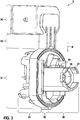
- the contacting component 5 is in FIG. 2 shown separately.
- the contacting component 5 has a main body, which is preferably made of a plastic material as an injection molded component in one piece.
- the main body has a drive module section 51 and a connector section 52, which are connected to one another via a connecting section 53.
- the contacting component 5 is preferably made of an electrically non-conductive material, such as a plastic material, in one piece, for example in an injection molding process, and serves to ensure contact of the brushes in the drive module section 51 via the connector of the connector portion 52.
- the connector of the connector portion 52 includes protruding pins that can be contacted via a suitable male connector.
- the contact pins are formed by the ends of punched grid lines 62 of a stamped grid, which are embedded in particular in the connecting portion 53 in the material of the contacting component 5.
- the punched grid lines 62 of the stamped grid serve as supply lines for the drive motor. 2
- the drive module section 51 has a first holding section 54 with holding structures, which are inserted into the second end 24 of the pole housing 21, so that the contacting component 5 is firmly seated on the pole housing 21 of the drive motor 2.
- the contacting component 5 and the pole housing 21 may be connected together by connecting elements 26, e.g. Be connected screws.
- the brushes are arranged in corresponding brush carriers to electrically contact the commutator located on the rotor shaft of the drive motor 2.
- the first holding section 54 is adjoined by a brush carrier base 55 of the main body of the contacting component 5.
- a second holding section 56 with corresponding holding structures is provided, which project into the gear housing 3 in the installed state and thereby connect the contacting component 5 to the gear housing 3.
- the second holding portion 56 of the main body has a circuit surface 57, which may be aligned in particular parallel to the axis of the motor shaft and in the direction of the connecting portion 53.
- the circuit surface 57 may also be used on other surfaces, e.g. the first holding portion or the brush holder base 55 may be provided.
- a conductor 58 is applied directly to the surface of the material of the main body of the contacting component 5 by means of a suitable technique.
- the conductor 58 may be formed for example of copper, silver or other conductive material.
- the Conductor 58 can be applied to the material of the contacting component 5 by means of various methods.
- SMD components 59 are applied by means of a suitable method, for example by means of a conductive adhesive or by soldering, so that the SMD components 59 are reliably held on the conductor track 58 and contact them electrically.
- the devices 59 may include EMC devices, such as choke inductors or capacitors, and further include one or more sensor devices, such as a Hall effect sensor, disposed on the circuit surface 57 so as to be in a direction perpendicular to the axial direction of the motor shaft a ring magnet (not shown) on the motor shaft (not shown).
- the conductor 58 is provided on the circuit surface 57 as a MID ( Molded Interconnect Device ).
- the circuit surface 57 may be printed with a sheet of an electrically conductive material, such as a copper foil, using a hot stamping die, which images the structures of the conductor 58 as heated embossing surfaces, so that the areas of the film acted upon by the hot stamping die merge with the plastic material of the circuit surface 57 and adhere to the plastic material when the film is removed, while the other regions of the metal foil are not connected to the circuit surface 57 and detach from it.
- an electrically conductive material such as a copper foil
- the circuit area 57 may be sprayed over a mask with conductive metal particles which are suitably adherent.
- a spray of silver particles may be sprayed onto the circuit surface 57 through the patterning mask, where bonding of the metal particles to the material of the circuit surface 57 may be achieved by means of a suitable adhesive, temperature, or sufficiently high impact energy.
- solvents or the like may also be added to the spray in order to permanently bond the metal particles to the material of the contacting component 5.
- the circuit area 57 can be described by means of a laser direct structuring according to the structures of the conductor tracks so that the material, in particular the plastic material, of the contacting component 5 is activated, in order then to be galvanically metallized. This process is also known as chemical galvanizing.
- FIG. 3 2 shows a further perspective view of the contacting component 5, namely in a viewing direction parallel to the extension of the circuit surface 57.
- the mounting direction B is seen as a direction perpendicular to the circuit surface 57.
- the SMD components 59 are applied to the conductor 58 in the direction of the mounting direction B. and then fixed or soldered with the conductive adhesive.
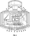
- FIG. 4 shows a plan view of the circuit surface 57.
- the connecting portion 53 connects, are embedded in the lead frame lines 62 as leads to the drive motor 2.
- the circuit surface 57 is substantially perpendicular or transverse to the extension direction of the lead frame lines 62.
- openings 60 are provided in the material of the contacting component 5 to expose the lead frame lines 62 thereon.
- the conductor 58 is guided to the openings 60.
- the circuit formed by the SMD components 59 is now contacted by the openings 60 with the lead frame lines 62.
- the conductor 58 is provided with the openings 60 facing the ends 61.
- a contacting of the lead frame lines 62 with the ends 61 of the conductor 58 can be made in one step of the conductive bonding of the components 59 on the conductor 58.
- a glue point of conductive adhesive must be introduced into the openings 60, so that the glue point extends from the punched grid lines 62 to the ends 61 of the conductor 58 and thereby produces an electrical contact.
- the glue point is then in the opening 60, contacts the exposed portion of the respective lead frame line 62 and has a size sufficient to also come into electrical contact with the end 61 of the conductor 58.
- the SMD components 59 By providing the SMD components 59 on the circuit surface 57, a space for leaded components or for a printed circuit board, such as a suppression board, can be saved. Due to the low height of the SMD components 59, the provision of additional space for introducing the components 59 is generally not necessary, so that the entire drive module 1 can be constructed to save space. In addition, improved electrical properties are to be expected, since the components 59 can be connected with a shorter connection to the lead frame lines 62.
- FIG. 5 Another contacting component 50 is in FIG. 5 shown separately.
- the contacting component 50 has, as in the above embodiment, a drive module portion 51 and a connector portion 52, which are connected to each other via a connecting portion 53.
- the circuit surface 57 is not arranged transversely, but parallel to the extension direction of the lead frame lines 62, wherein the conductor 58 extends on a lead surface 65, which extends as part of the circuit surface transverse to the extension direction of the lead frame lines 62, so that a contact with the lead frame lines 62 can be done in the manner described above.
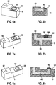
- FIG. 6a - 6b is a perspective and cross-sectional view through a further embodiment of the connection region between one of the lead frame lines 62 and the conductor 58 shown.
- the lead frame line 62 is brought to the conductor track 58 and adjacent thereto.
- a conductive adhesive point 63 which extends over a portion of the conductor 58 and a portion of the lead frame line 62, an electrical connection can be made.
- FIGS. 7a and 7b is a perspective and cross-sectional view through the connection region between one of the lead frame lines 62 and the conductor 58 shown in a further variant.
- a recess 64 is provided, wherein on the surface on which the recess 64 is provided, the conductor 58 is located.
- the recess 64 can penetrate the conductor track 58.
- the lead frame line 62 may include a branching structure 66 which reduces thermal stresses.
- FIGS. 8a and 8b is a perspective and cross-sectional view through the connection region between one of the lead frame lines 62 and the conductor 58 shown in a further variant.
- one of the lead frame lines 62 protrudes from the body of the contacting component 5 and the conductor track 58 is arranged around the protruding section of the lead frame line 62.
Landscapes
- Engineering & Computer Science (AREA)
- Power Engineering (AREA)
- Manufacturing & Machinery (AREA)
- Microelectronics & Electronic Packaging (AREA)
- Physics & Mathematics (AREA)
- Electromagnetism (AREA)
- Manufacture Of Motors, Generators (AREA)
- Motor Or Generator Frames (AREA)
- Motor Or Generator Current Collectors (AREA)
Description
- Die vorliegende Erfindung betrifft Antriebsmodule, insbesondere Antriebsmodule mit Elektromotoren. Die Erfindung betrifft weiterhin insbesondere die Anordnung von EMV-Bauelementen und/oder Sensoren zur Rotorlageerfassung in elektrischen Maschinen für Antriebsmodule.
- Elektromotoren in Antriebsmodulen, wie beispielsweise Fensterheber-Antriebsmodulen in Kraftfahrzeugen, können als bürstenkommutierte Gleichstrommotoren vorgesehen sein. Derartige Elektromotoren sind mit Bürstenträgern versehen, die Bürsten zur elektrischen Kommutierung des Elektromotors halten. Die Bürsten stehen üblicherweise über ein Stanzgitter mit einem externen Steckeranschluss in elektrischer Verbindung.
- Zur Reduzierung von EMV-Störsignalen auf den Zuleitungen sind EMV-Bauelemente und/oder Sensoren für eine Rotorlageerfassung elektrisch an Stanzgitterleitungen des Stanzgitters angeschlossen. Die EMV-Bauelemente und/oder -Sensoren können als bedrahtete Bauelemente vorgesehen sein, die durch einen Schweiß- oder Lötprozess mit den Stanzgitterleitungen verbunden werden.
- Zur Einsparung von Bauraum können die bedrahteten Bauelemente durch SMD-Bauelemente ersetzt werden, die entweder direkt mit den Stanzgitterleitungen verbunden werden oder auf eine geeignete Leiterplatte aufgesetzt sind, die elektrisch mit den Stanzgitterleitungen verbunden wird. Das elektrische Kontaktieren von SMD-Bauelementen gestaltet sich jedoch in der Praxis häufig aufwändig.
- Elektrische Maschinen für Antriebsmodule werden in der Regel mit einem Poltopfgehäuse und einer stirnseitig darauf aufgesetzten Kontaktierungskomponente versehen, die Bürstenträger zur Aufnahme von Bürsten bereitstellt, über die der Läufer der elektrischen Maschine elektrisch kontaktiert werden kann. Die Kontaktierungskomponente weist weiterhin Stanzgitterleitungen auf, die an einem Steckeranschluss enden, wobei zwischen dem Steckeranschluss und den Bürsten eine Schaltung aus SMD-Bauelementen und/oder einem oder mehreren Sensoren für eine Rotorlageerkennung angeordnet ist. Die Anordnung der Bauelemente vergrößert den benötigten Bauraum und beeinflusst damit die Gesamtgröße eines Antriebsmoduls, in dem das Bürstenträgerelement eingesetzt ist.
- Es ist Aufgabe der vorliegenden Erfindung, eine Kontaktierungskomponente für ein Antriebsmodul zur Verfügung zu stellen, die der Aufnahme von Bürstenträgern und deren elektrischer Kontaktierung dient. Weiterhin soll die Kontaktierungskomponente in raumsparender Weise mit elektrischen Bauelementen, insbesondere EMV-Bauelementen und/oder einem oder mehreren Sensorbauelementen, versehen werden.
- Mit der
WO 01/80407 A1 WO 01/59915 A1 DE 10 2006 055 159 A1 weist ein Bürstensystem auf, das zumindest teilweise auf einer Leiterplatte angeordnet ist, die zumindest teilweise mit dem Kunststoff des Getriebegehäuses umsprizt ist. - Mit der
US 2009/251030 A1 ist eine elektronisch kommutierte permanentmagneterregte Synchronmaschine bekannt geworden, bei der elektrische Verbindungselemente als Einlegeteile zwischen zwei Elektroniksubstraten eingegossen sind. - Die
DE 10 2004 059 912 A1 offenbart eine elektrische Maschine umfassend einen Bürstenträger mit Flexfolie. - Diese Aufgabe wird durch die Kontaktierungskomponente für ein Antriebsmodul gemäß Anspruch 1, ein Verfahren gemäß Anspruch 10 sowie durch die elektrische Maschine und das Antriebsmodul gemäß den nebengeordneten Ansprüchen gelöst. Weitere vorteilhafte Ausgestaltungen der vorliegenden Erfindung sind in den abhängigen Ansprüchen angegeben.
- Gemäß einem ersten Aspekt ist eine Kontaktierungskomponente für ein Antriebsmodul vorgesehen, umfassend:
- einen elektrisch nicht leitenden Grundkörper zum Bereitstellen einer Kontaktierung eines bürstenkommutierten Antriebsmotors über Bürsten;
- mindestens eine Zuleitung, insbesondere eine Stanzgitterleitung, zum elektrischen Kontaktieren des Antriebsmotors;
- eine Schaltungsfläche des Grundkörpers, auf der mittels einer MID-Technik eine Leiterbahn unmittelbar aufgebracht ist; und
- mindestens ein elektrisches Bauelement, insbesondere ein SMD-Bauelement, das elektrisch mit der Leiterbahn verbunden ist.
- Eine Idee der obigen Kontaktierungskomponente besteht darin, den Grundkörper der Kontaktierungskomponente mit einer Schaltungsfläche vorzusehen, auf die unmittelbar eine Leiterbahn aufgebracht ist. Mit anderen Worten wird die Leiterbahn unmittelbar auf das nicht leitende Material, insbesondere das Kunststoffmaterial, des Grundkörpers der Kontaktierungskomponente aufgebracht. Auf diese Weise ist es möglich, sowohl auf bedrahtete Bauelemente als auch auf Leiterplatten zum Anschließen von SMD-Bauelementen zu verzichten und damit den für das Einbringen der Bauelemente benötigten Bauraum deutlich zu reduzieren.
- Weiterhin ist es möglich, herkömmliche SMD-Bauelemente zum Aufbringen auf die auf der Fläche der Kontaktierungskomponente aufgebrachte Leiterbahn zu verwenden.
- Darüber hinaus kann die Kontaktierungskomponente mit einer vereinfachten Geometrie vorgesehen werden, da Halterungen für Bauelemente bzw. Leiterplatten entfallen können. Die Kontaktierungskomponente wird häufig als Spritzgusskomponente hergestellt, wodurch der Aufwand für die Herstellung deutlich reduziert und weiterhin Kunststoffmaterial eingespart werden kann.
- Zudem kann aufgrund der kürzeren Anbindungen von EMV-Bauelementen ein verbessertes EMV-Verhalten erreicht werden.
- Weiterhin kann die mindestens eine Zuleitung zumindest abschnittsweise in einer Erstreckungsrichtung verlaufen, wobei die Schaltungsfläche quer zur Erstreckungsrichtung angeordnet ist.
- Alternativ kann die mindestens eine Zuleitung zumindest abschnittsweise in einer Erstreckungsrichtung verlaufen, wobei die Schaltungsfläche parallel zur Erstreckungsrichtung angeordnet ist und wobei die Leiterbahn zur Kontaktierung der mindestens einen Zuleitung auf eine benachbarte Zuleitungsfläche geführt wird, die quer zur Erstreckungsrichtung angeordnet ist.
- Gemäß einer Ausführungsform kann vorgesehen sein, dass das Bauelement mit der Leiterbahn und/oder die Leiterbahn mit der mindestens einen Zuleitung verbunden ist, indem ein leitfähiges Material, insbesondere ein leitfähiger Klebstoff oder ein Lotmaterial zwischen einen Kontakt des Bauelements und die Leiterbahn bzw. zwischen die mindestens eine Zuleitung und die Leiterbahn aufgebracht wird.
- Es kann vorgesehen sein, dass ein Abschnitt der Zuleitung über eine Öffnung nahe einem Ende der zu kontaktierenden Leiterbahn zugänglich ist, wobei ein Abschnitt der Zuleitung die zu kontaktierende Leiterbahn durchdringt oder wobei ein Abschnitt der Zuleitung an einer Oberfläche der Kontaktierungskomponente geführt ist und die Leiterbahn an den Abschnitt der Zuleitung angrenzt.
- Gemäß einem weiteren Aspekt ist ein Antriebsmodul vorgesehen, das einen Antriebsmotor und die obige Kontaktierungskomponente umfasst, die mit dem Antriebsmotor verbunden ist, um eine Kontaktierung des Antriebsmotors über die Zuleitungen bereitzustellen.
- Weiterhin kann das Antriebsmodul in ein Gehäuse des Antriebsmotors eingesetzt sein.
- An einer dem Antriebsmotor gegenüberliegenden Seite der Kontaktierungskomponente kann ein Getriebegehäuse angeordnet sein, wobei die Schaltungsfläche in das Getriebegehäuse hineinragt.
- Gemäß einem weiteren Aspekt ist ein Verfahren zum Herstellen einer Kontaktierungskomponente für ein Antriebsmodul vorgesehen, das die folgenden Schritte umfasst:
- Bereitstellen eines nicht leitenden Grundkörpers, insbesondere aus einem Kunststoffmaterial, mit mindestens einer zumindest teilweise eingebetteten Zuleitung zum Bereitstellen einer Kontaktierung eines bürstenkommutierten Antriebsmotors;
- Aufbringen einer Leiterbahn unmittelbar auf eine Schaltungsfläche des Grundkörpers mittels einer MID-Technik; und
- elektrisches Kontaktieren mindestens eines elektrischen Bauelements, insbesondere eines SMD-Bauelements, über die Leiterbahn.
- Weiterhin kann vorgesehen sein, dass das elektrische Kontaktieren des elektrischen Bauelements mithilfe eines aushärtenden leitfähigen Materials, insbesondere eines leitfähigen Klebstoffs, erfolgt.
- Es kann vorgesehen sein, dass das elektrische Bauelement mithilfe eines aushärtenden leitfähigen Materials, insbesondere eines leitfähigen Klebstoffes, elektrisch kontaktiert wird.
- Weiterhin kann die Leiterbahn durch eines der folgenden Verfahren auf die Schaltungsfläche aufgebracht werden:
- Bedrucken mit einer Folie aus einem leitfähigen Material unter Verwendung eines Heißprägestempel, der die Strukturen der Leiterbahn als Prägeflächen abbildet, so dass der mit dem Heißprägestempel beaufschlagte Bereich der Folie mit dem Material des Grundkörpers verschmilzt und beim Abziehen der Folie an dem Grundkörper haften bleibt, während der übrige Bereich der Folie sich von der Schaltungsfläche löst;
- Besprühen der Schaltungsfläche durch eine Strukturierungsmaske mit leitfähigen Metallpartikeln, die haftend ausgebildet sind, so dass die Struktur der Leiterbahn entsprechend der Strukturierungsmaske auf der Schaltungsfläche ausgebildet wird; und
- Beschreiben der Schaltungsfläche mithilfe einer Laser-Direktstrukturierung entsprechend der Struktur der Leiterbahn, so dass das Material des Grundkörpers im Bereich der aufzubringenden Leiterbahn aktiviert wird, wobei die Leiterbahn durch galvanisches Metallisieren des aktivierten Bereichs hergestellt wird.
- Bevorzugte Ausführungsformen der vorliegenden Erfindung werden nachfolgend anhand der beigefügten Zeichnungen näher erläutert. Es zeigen:
- Figur 1
- eine Darstellung eines Antriebsmoduls mit einem Antriebsmotor und einem Getriebegehäuse, die über eine Kontaktierungskomponente miteinander verbunden sind;
- Figur 2
- eine Darstellung einer Kontaktierungskomponente mit aufgebrachten Bauelementen;
- Figur 3
- eine Darstellung der Kontaktierungskomponente aus einer weiteren Blickrichtung zur Darstellung der Bestückungsrichtung für die Bauelemente;
- Figur 4
- eine detailliertere Darstellung der Schaltungsfläche und der Kontaktierung der Stanzgitterleitungen;
- Figur 5
- eine Darstellung einer weiteren Kontaktierungskomponente mit aufgebrachten Bauelementen;
- Figuren 6a und 6b
- eine perspektivische und Schnittdarstellung einer Kontaktierungsart zwischen einer Stanzgitterleitung und einer Leiterbahn auf der Schaltungsfläche;
- Figuren 7a und 7b
- eine perspektivische und Schnittdarstellung einer weiteren Kontaktierungsart zwischen einer Stanzgitterleitung und einer Leiterbahn auf der Schaltungsfläche; und
- Figuren 8a und 8b
- eine perspektivische und Schnittdarstellung einer weiteren Kontaktierungsart zwischen einer Stanzgitterleitung und einer Leiterbahn auf der Schaltungsfläche;
-
Figur 1 zeigt eine perspektivische Darstellung eines Antriebsmoduls 1 in Form eines Fensterhebermoduls zum Einsatz in Kraftfahrzeugen mit elektrischen Fensterhebern. Das Antriebsmodul 1 weist einen Antriebsmotor 2 auf, der an einem Getriebegehäuse 3 angeordnet ist. Aus dem Getriebegehäuse 3 ragt eine Abtriebswelle 4 zum Antrieb einer Mechanik, wie z.B. zum Heben oder Senken einer Fensterscheibe in einem elektrischen Fensterhebersystem eines Kraftfahrzeugs. Zwischen dem Getriebegehäuse 3 und dem Antriebsmotor 2 ist eine Kontaktierungskomponente 5 angeordnet, die den Antriebsmotor 2 und das Getriebegehäuse 3 mechanisch miteinander verbindet. - Der Antriebsmotor 2 ist in einem Polgehäuse 21 aufgenommen, das an einem ersten Ende 22 eine Lageraufnahme 23 zur gelagerten Aufnahme einer (nicht gezeigten) Motorwelle bereitstellt. An einem dem ersten Ende 22 gegenüberliegenden Ende 24 des Polgehäuses 21 ist die Kontaktierungskomponente 5 angeordnet.
- Der Antriebsmotor 2 ist so ausgebildet, dass ein an der Motorwelle angeordneter Kommutator in die Kontaktierungskomponente 5 hineinragt und dort von in einem Bürstenträger gehaltenen Bürsten (nicht gezeigt) kontaktiert wird. Die Motorwelle durchdringt die Kontaktierungskomponente 5 und ragt in das Getriebegehäuse 3 hinein, wo sie beispielsweise mit einem Schneckenrad verbunden sein kann, um in ein entsprechendes in dem Getriebegehäuse 3 angeordnetes Getriebe einzugreifen.
- Die Kontaktierungskomponente 5 ist in
Figur 2 separat dargestellt. Die Kontaktierungskomponente 5 weist einen Grundkörper auf, der vorzugsweise aus einem Kunststoffmaterial als Spritzgußbauteil einstückig gefertigt ist. - Der Grundkörper weist einen Antriebsmodulabschnitt 51 und einen Steckverbinderabschnitt 52 auf, die über einen Verbindungsabschnitt 53 miteinander verbunden sind. Die Kontaktierungskomponente 5 ist vorzugsweise aus einem elektrisch nicht leitenden Material, wie beispielsweise einem Kunststoffmaterial, einstückig, beispielsweise in einem Spritzgussverfahren, hergestellt und dient dazu, eine Kontaktierung der Bürsten in dem Antriebsmodulabschnitt 51 über den Steckverbinder des Steckverbinderabschnitts 52 zu gewährleisten.
- Der Steckverbinder des Steckverbinderabschnitt 52 enthält hervorstehende Kontaktstifte, die über einen geeigneten Steckeranschluss kontaktiert werden können. Die Kontaktstifte werden durch die Enden von Stanzgitterleitungen 62 eines Stanzgitters gebildet, die insbesondere in dem Verbindungsabschnitt 53 in dem Material der Kontaktierungskomponente 5 eingebettet sind. Das Stanzgitterleitungen 62 des Stanzgitters dienen als Zuleitungen für den Antriebsmotor 2.
- Der Antriebsmodulabschnitt 51 weist einen ersten Halteabschnitt 54 mit Haltestrukturen auf, die in das zweite Ende 24 des Polgehäuses 21 eingesetzt werden, so dass die Kontaktierungskomponente 5 fest auf dem Polgehäuse 21 des Antriebsmotors 2 aufsitzt. Die Kontaktierungskomponente 5 und das Polgehäuse 21 können miteinander durch Verbindungselemente 26, wie z.B. Schrauben verbunden sein. In dem ersten Halteabschnitt 54 der Kontaktierungskomponente 5 sind die Bürsten in entsprechenden Bürstenträgern angeordnet, um den an der Rotorwelle des Antriebsmotors 2 befindlichen Kommutator elektrisch zu kontaktieren.
- An den ersten Halteabschnitt 54 schließt sich eine Bürstenträgerbasis 55 des Grundkörpers der Kontaktierungskomponente 5 an. An der dem ersten Halteabschnitt 54 gegenüberliegenden Seite der Bürstenträgerbasis 55 ist ein zweiter Halteabschnitt 56 mit entsprechenden Haltestrukturen vorgesehen, die im montierten Zustand in das Getriebegehäuse 3 hineinragen und dadurch die Kontaktierungskomponente 5 mit dem Getriebegehäuse 3 verbinden.
- Der zweite Halteabschnitt 56 des Grundkörpers weist eine Schaltungsfläche 57 auf, die insbesondere zur Achse der Motorwelle parallel und in Richtung des Verbindungsabschnitts 53 ausgerichtet sein kann. Alternativ kann die Schaltungsfläche 57 auch auf anderen Flächen, wie z.B. dem ersten Halteabschnitt oder der Bürstenträgerbasis 55 vorgesehen sein.
- Auf die Schaltungsfläche 57 wird mithilfe einer geeigneten Technik eine Leiterbahn 58 direkt auf die Oberfläche des Materials des Grundkörpers der Kontaktierungskomponente 5 aufgebracht. Die Leiterbahn 58 kann beispielsweise aus Kupfer, Silber oder einem sonstigen leitfähigen Material ausgebildet sein. Die Leiterbahn 58 kann mithilfe verschiedener Verfahren auf das Material der Kontaktierungskomponente 5 aufgebracht werden.
- Auf die Leiterbahn 58 werden mittels eines geeigneten Verfahrens SMD-Bauelemente 59 aufgebracht, beispielsweise mithilfe eines leitfähigen Klebers oder durch Löten, so dass die SMD-Bauelemente 59 zuverlässig an der Leiterbahn 58 gehalten sind und diese elektrisch kontaktieren. Die Bauelemente 59 können EMV-Bauelemente, wie beispielsweise Drosselinduktivitäten oder Kapazitäten, umfassen und darüber hinaus ein oder mehrere Sensorbauelemente, wie beispielsweise einen Hallsensor, aufweisen, der so an der Schaltungsfläche 57 angeordnet ist, dass er in einer Richtung senkrecht zur axialen Richtung der Motorwelle einem (nicht gezeigten) Ringmagneten an der (nicht gezeigten) Motorwelle gegenüberliegt. Die Leiterbahn 58 wird auf der Schaltungsfläche 57 als MID (Molded Interconnect Device) vorgesehen.
- In einem ersten Verfahren zum Aufbringen einer Leiterbahn kann die Schaltungsfläche 57 mit einer Folie aus einem elektrisch leitfähigen Material, wie beispielsweise einer Kupferfolie, bedruckt werden, und zwar unter Verwendung eines Heißprägestempels, der die Strukturen der Leiterbahn 58 als erwärmte Prägeflächen abbildet, so dass die mit dem Heißprägestempel beaufschlagten Bereiche der Folie mit dem Kunststoffmaterial der Schaltungsfläche 57 verschmelzen und beim Abziehen der Folie an dem Kunststoffmaterial haften bleiben, während die übrigen Bereiche der Metallfolie nicht mit der Schaltungsfläche 57 verbunden werden und sich von dieser lösen.
- In einem weiteren Verfahren kann die Schaltungsfläche 57 über eine Maske mit leitfähigen Metallpartikeln besprüht werden, die in geeigneter Weise haftend ausgebildet sind. Beispielsweise kann ein Spray aus Silberpartikeln durch die Strukturierungsmaske auf die Schaltungsfläche 57 aufgesprüht werden, wobei das Verbinden der Metallpartikel mit dem Material der Schaltungsfläche 57 mittels eines geeigneten Klebstoffs, einer Temperatur oder einer ausreichend hohen Aufprallenergie erreicht werden kann. Alternativ oder zusätzlich kann dem Spray auch Lösungsmittel oder dergleichen zugesetzt sein, um die Metallpartikel dauerhaft mit dem Material der Kontaktierungskomponente 5 zu verbinden.
- Mithilfe eines dritten Verfahrens kann die Schaltungsfläche 57 mittels einer Laser-Direktstrukturierung entsprechend der Strukturen der Leiterbahnen so beschrieben werden, dass das Material, insbesondere das Kunststoffmaterial, der Kontaktierungskomponente 5 aktiviert wird, um dann galvanisch metallisiert werden zu können. Dieser Prozess wird auch als chemisches Galvanisieren bezeichnet.
- In
Figur 3 ist eine weitere perspektivische Darstellung der Kontaktierungskomponente 5 gezeigt, und zwar in einer Betrachtungsrichtung parallel zur Erstreckung der Schaltungsfläche 57. Man erkennt die Bestückungsrichtung B als Richtung senkrecht zur Schaltungsfläche 57. In Richtung der Bestückungsrichtung B werden die SMD-Bauelemente 59 auf die Leiterbahn 58 aufgebracht und anschließend mit dem leitfähigen Klebstoff fixiert oder angelötet. -
Figur 4 zeigt eine Draufsicht auf die Schaltungsfläche 57. An die Schaltungsfläche 57 schließt sich der Verbindungsabschnitt 53 an, in den Stanzgitterleitungen 62 als Zuleitungen zu dem Antriebsmotor 2 eingebettet sind. Die Schaltungsfläche 57 steht im Wesentlichen senkrecht bzw. quer zu der Erstreckungsrichtung der Stanzgitterleitungen 62 ab. An der Position, an der die Schaltungsfläche 57 auf der Bürstenträgerbasis 55 aufsitzt, sind in dem Material der Kontaktierungskomponente 5 Öffnungen 60 vorgesehen, um dort die Stanzgitterleitungen 62 freizulegen. Die Leiterbahn 58 ist zu den Öffnungen 60 geführt. Die durch die SMD-Bauelemente 59 gebildete Schaltung wird nun durch die Öffnungen 60 mit den Stanzgitterleitungen 62 kontaktiert. - Wie in
Figur 4 dargestellt, ist die Leiterbahn 58 mit an den Öffnungen 60 zugewandten Enden 61 versehen. Eine Kontaktierung der Stanzgitterleitungen 62 mit den Enden 61 der Leiterbahn 58 kann in einem Arbeitsschritt des leitfähigen Verklebens der Bauelemente 59 auf der Leiterbahn 58 vorgenommen werden. Dazu muss ein Klebepunkt aus leitfähigem Klebstoff in die Öffnungen 60 eingebracht werden, so dass sich der Klebepunkt von den Stanzgitterleitungen 62 bis zu den Enden 61 der Leiterbahn 58 erstreckt und dadurch eine elektrische Kontaktierung herstellt. Der Klebepunkt befindet sich dann in der Öffnung 60, kontaktiert den freiliegenden Abschnitt der betreffenden Stanzgitterleitung 62 und weist eine ausreichende Größe auf, um ebenfalls in elektrischen Kontakt mit dem Ende 61 der Leiterbahn 58 zu gelangen. - Durch das Vorsehen der SMD-Bauelemente 59 auf der Schaltungsfläche 57 kann ein Bauraum für bedrahtete Bauelemente bzw. für eine Leiterplatte, wie beispielsweise eine Entstörplatine, eingespart werden. Durch die geringe Bauhöhe der SMD-Bauelemente 59 ist das Vorsehen von zusätzlichem Bauraum zum Einbringen der Bauelemente 59 in der Regel nicht notwendig, so dass das gesamte Antriebsmodul 1 Platz sparend aufgebaut werden kann. Zudem sind verbesserte elektrische Eigenschaften zu erwarten, da die Bauelemente 59 mit kürzerer Anbindung an die Stanzgitterleitungen 62 angeschlossen werden können.
- Eine weitere Kontaktierungskomponente 50 ist in
Figur 5 separat dargestellt. Die Kontaktierungskomponente 50 weist wie bei der obigen Ausführungsform einen Antriebsmodulabschnitt 51 und einen Steckverbinderabschnitt 52 auf, die über einen Verbindungsabschnitt 53 miteinander verbunden sind. Im Unterschied ist jedoch die Schaltungsfläche 57 nicht quer, sondern parallel zur Erstreckungsrichtung der Stanzgitterleitungen 62 angeordnet, wobei die Leiterbahn 58 sich auf eine Zuleitungsfläche 65 erstreckt, die als Teil der Schaltungsfläche quer zur Erstreckungsrichtung der Stanzgitterleitungen 62 verläuft, so dass eine Kontaktierung mit den Stanzgitterleitungen 62 in der oben beschriebenen Weise erfolgen kann. - In den
Figuren 6a - 6b ist eine perspektivische und Querschnittsdarstellung durch eine weitere Ausgestaltung des Verbindungsbereichs zwischen einer der Stanzgitterleitungen 62 und der Leiterbahn 58 dargestellt. In der gezeigten Ausführungsform ist dargestellt, dass die Stanzgitterleitung 62 an die Leiterbahn 58 herangeführt ist und an diese angrenzt. Durch Aufbringen eines leitfähigen Klebepunkts 63, der sich über einen Teil der Leiterbahn 58 und einen Teil der Stanzgitterleitung 62 erstreckt, kann eine elektrische Verbindung hergestellt werden. - In den
Figuren 7a und 7b ist eine perspektivische und Querschnittsdarstellung durch den Verbindungsbereich zwischen einer der Stanzgitterleitungen 62 und der Leiterbahn 58 in einer weiteren Variante dargestellt. In der gezeigten Ausführungsform ist eine Ausnehmung 64 vorgesehen, wobei an der Oberfläche, an der die Ausnehmung 64 vorgesehen ist, sich die Leiterbahn 58 befindet. Insbesondere kann die Ausnehmung 64 die Leiterbahn 58 durchdringen. Durch Einbringen eines Klebetropfens 67, der die Ausnehmung 64 vollständig ausfüllt, kann die elektrische Verbindung hergestellt werden. Um die Verbindung mit dem leitfähigen Klebstoff thermisch zu entlasten, kann die Stanzgitterleitung 62 eine abzweigende bzw. abstehende Struktur 66 aufweisen, durch die thermische Spannungen reduziert werden. - In den
Figuren 8a und 8b ist eine perspektivische und Querschnittsdarstellung durch den Verbindungsbereich zwischen einer der Stanzgitterleitungen 62 und der Leiterbahn 58 in einer weiteren Variante dargestellt. In der gezeigten Ausführungsform ist dargestellt, dass eine der Stanzgitterleitungen 62 aus dem Körper der Kontaktierungskomponente 5 herausragt und die Leiterbahn 58 um den herausragenden Abschnitt der Stanzgitterleitung 62 angeordnet ist. Durch Aufbringen des leitfähigen Klebstoffs auf den herausragenden Abschnitt der Stanzgitterleitung 62 kann eine elektrische Verbindung zwischen der Stanzgitterleitung 62 und der Leiterbahn 58 hergestellt werden.
Claims (13)
- Kontaktierungskomponente (5) - insbesondere ein Bürstenhalterbauteil - für ein Antriebsmodul (1), umfassend:- einen Grundkörper zum Bereitstellen einer Kontaktierung eines bürstenkommutierten Antriebsmotors (2) über Bürsten;- mindestens eine Zuleitung (62), insbesondere eine Stanzgitterleitung, zum elektrischen Kontaktieren des Antriebsmotors (2);- eine Schaltungsfläche (57), auf der mittels einer MID-Technik eine Leiterbahn (58) unmittelbar aufgebracht ist; und- mindestens ein Bauelement (59), insbesondere ein SMD-Bauelement (59), das mit der Leiterbahn (58) elektrisch verbunden ist wobei der Grundkörper einen Antriebsmodulabschnitt (51) und einen Steckverbinderabschnitt (52) aufweist, die über einen Verbindungsabschnitt (53) miteinander verbunden sind, und der Grundkörper einstückig aus einem Kunststoffmaterial hergestellt ist, und der Antriebsmodulabschnitt (51) einen ersten Halteabschnitt (54) mit Haltestrukturenaufweist, die in ein Polgehäuse (21) einsetzbar sind, so dass die Kontaktierungskomponente (5) fest auf dem Polgehäuse (21) des Antriebsmotors (2) aufsitzt, wobei in dem ersten Halteabschnitt (54) der Kontaktierungskomponente (5) die Bürsten in entsprechenden Bürstenträgern angeordnet sind, wobei sich an den ersten Halteabschnitt (54) eine Bürstenträgerbasis (55) des Grundkörpers der Kontaktierungskomponente (5) anschließt, und an der dem ersten Halteabschnitt (54) gegenüberliegenden Seite der Bürstenträgerbasis (55) ein zweiter Halteabschnitt (56) mit entsprechenden Haltestrukturen vorgesehen ist, die im montierten Zustand in
ein Getriebegehäuse (3) hineinragen und dadurch die Kontaktierungskomponente (5) mit dem Getriebegehäuse (3)
verbinden, wobei die Schaltungsfläche (57) in das Getriebegehäuse (3)
hineinragt, wobei der zweite Halteabschnitt (56) des Grundkörpers die Schaltungsfläche (57) aufweist, wobei auf die Schaltungsfläche (57) die Leiterbahn (58) direkt auf die Oberfläche des Materials des Grundkörpers aufgebracht ist, und
wobei das mindestens eine Bauelement (59) einen Hallsensor umfasst, der so an der Schaltungsfläche (57) angeordnet ist, dass er im
montierten Zustand der
Kontaktierungskomponente (5) in einer Richtung senkrecht zur Richtung
einer Motorwelle einem Ringmagneten an der Motorwelle
gegenüberliegt. - Kontaktierungskomponente (5) nach Anspruch 1, wobei die mindestens eine Zuleitung (62) zumindest abschnittsweise in einer Erstreckungsrichtung verläuft, wobei die Schaltungsfläche (57) quer zur Erstreckungsrichtung angeordnet ist.
- Kontaktierungskomponente (5) nach Anspruch 1, wobei die mindestens eine Zuleitung (62) zumindest abschnittsweise in einer Erstreckungsrichtung verläuft, wobei die Schaltungsfläche (57) parallel zur Erstreckungsrichtung angeordnet ist und wobei die Leiterbahn (58) zur Kontaktierung der mindestens einen Zuleitung (62) auf eine benachbarte Zuleitungsfläche (65) geführt wird, die quer zur Erstreckungsrichtung angeordnet ist.
- Kontaktierungskomponente (5) nach Anspruch 2 oder 3, wobei das Bauelement (59) mit der Leiterbahn (58) und/oder die Leiterbahn (58) mit der mindestens einen Zuleitung (62) verbunden ist, indem ein leitfähiges Material, insbesondere ein leitfähiger Klebstoff oder ein Lotmaterial zwischen einen Kontakt des Bauelements (59) und die Leiterbahn (58) bzw. zwischen die mindestens eine Zuleitung (62) und die Leiterbahn (58) aufgebracht wird.
- Kontaktierungskomponente (5) nach Anspruch 4,
wobei ein Abschnitt der Zuleitung (62) über eine Öffnung (64) nahe einem Ende (61) der zu kontaktierenden Leiterbahn (58) zugänglich ist, oder wobei ein Abschnitt der Zuleitung (62) die zu kontaktierende Leiterbahn (58) durchdringt oder
wobei ein Abschnitt der Zuleitung (62) an einer Oberfläche der Kontaktierungskomponente (5) geführt ist und die Leiterbahn (58) an den Abschnitt der Zuleitung (62) angrenzt. - Kontaktierungskomponente (5) nach einem der vorhergehenden Ansprüche, wobei die der Grundkörper einen Durchbruch zur Aufnahme einer Rotorwelle eines Antriebsmotors (2) und einen elektrische Pins aufnehmenden Anschluss-Stecker (52) aufweist, und die Erstreckungsrichtung der mindestens eine Zuleitung (62) mit den Pins verbunden ist - und insbesondere die Erstreckungsrichtung in radialer Richtung zur Rotorwelle verläuft.
- Antriebsmodul (1) umfassend:- einen Antriebsmotor (2);- eine Kontaktierungskomponente (5) nach Anspruch 1 bis 6, die mit dem Antriebsmotor (2) verbunden ist, um eine Kontaktierung des Antriebsmotors (2) über die Zuleitungen (62) bereitzustellen.
- Antriebsmodul (1) nach Anspruch 7, wobei das Antriebsmodul (1) in das Polgehäuse (21) des Antriebsmotors (2) eingesetzt ist.
- Antriebsmodul (1) nach Anspruch 7 oder 8, wobei an einer dem Antriebsmotor (2) gegenüberliegenden Seite der Kontaktierungskomponente (5) ein Getriebegehäuse (3) angeordnet ist, wobei die Schaltungsfläche (57) in das Getriebegehäuse (3) hineinragt.
- Verfahren zum Herstellen einer Kontaktierungskomponente (5) für ein Antriebsmodul (1) nach einem der Ansprüche 1 - 6, mit folgenden Schritten:- Bereitstellen eines einstückigen, nicht leitenden Grundkörpers aus einem Kunststoffmaterial, mit mindestens einer zumindest teilweise eingebetteten Zuleitung (62) zum Bereitstellen einer Kontaktierung eines bürstenkommutierten Antriebsmotors (2);- Aufbringen einer Leiterbahn (58) unmittelbar auf eine Schaltungsfläche (57) direkt auf die Oberfläche des Materials des Grundkörpers mittels einer MID-Technik; und- elektrisches Kontaktieren mindestens eines elektrischen Bauelements (59), insbesondere eines SMD-Bauelements (59), über die Leiterbahn (58).
- Verfahren nach Anspruch 10, wobei das elektrische Bauelement (59) mittels eines aushärtenden leitfähigen Materials, insbesondere eines leitfähigen Klebstoffes, oder mit einer Lötverbindung elektrisch kontaktiert wird.
- Verfahren nach Anspruch 11, wobei eine elektrische Verbindung zwischen der mindestens einen Zuleitung (62) und der Leiterbahn (58) durch Aufbringen des aushärtenden leitfähigen Materials erfolgt.
- Verfahren nach Anspruch 12, wobei die Leiterbahn (58) durch eines der folgenden Verfahren zur MID-Technik auf die Schaltungsfläche (57) aufgebracht wird:- Bedrucken mit einer Folie aus einem leitfähigen Material unter Verwendung eines Heißprägestempels, der die Strukturen der Leiterbahn (58) als Prägeflächen abbildet, so dass der mit dem Heißprägestempel beaufschlagte Bereich der Folie mit dem Material des Grundkörpers verschmilzt und beim Abziehen der Folie an dem Grundkörper haften bleibt, während der übrige Bereich der Folie sich von der Schaltungsfläche (57) löst;- Besprühen der Schaltungsfläche (57) durch eine Strukturierungsmaske mit leitfähigen Metallpartikeln, die haftend ausgebildet sind, so dass die Struktur der Leiterbahn (58) entsprechend der Strukturierungsmaske auf der Schaltungsfläche ausgebildet wird;- Beschreiben der Schaltungsfläche (57) mithilfe einer Laser-Direktstrukturierung entsprechend der Struktur der Leiterbahn (58), so dass das Material des Grundkörpers im Bereich der aufzubringenden Leiterbahn (58) aktiviert wird, wobei die Leiterbahn (58) durch galvanisches Metallisieren des aktivierten Bereichs hergestellt wird.
Applications Claiming Priority (2)
| Application Number | Priority Date | Filing Date | Title |
|---|---|---|---|
| DE102013209233.4A DE102013209233A1 (de) | 2013-05-17 | 2013-05-17 | Kontaktierungskomponente für ein Antriebsmodul, Antriebsmodul sowie Verfahren zur Herstellung einer Kontaktierungskomponente |
| PCT/EP2014/054653 WO2014183899A2 (de) | 2013-05-17 | 2014-03-11 | Kontaktierungskomponente für ein antriebsmodul, antriebsmodul sowie verfahren zur herstellung einer kontaktierungskomponente |
Publications (2)
| Publication Number | Publication Date |
|---|---|
| EP2997645A2 EP2997645A2 (de) | 2016-03-23 |
| EP2997645B1 true EP2997645B1 (de) | 2018-08-01 |
Family
ID=50239651
Family Applications (1)
| Application Number | Title | Priority Date | Filing Date |
|---|---|---|---|
| EP14708899.1A Not-in-force EP2997645B1 (de) | 2013-05-17 | 2014-03-11 | Kontaktierungskomponente für ein antriebsmodul, antriebsmodul sowie verfahren zur herstellung einer kontaktierungskomponente |
Country Status (6)
| Country | Link |
|---|---|
| US (1) | US10153605B2 (de) |
| EP (1) | EP2997645B1 (de) |
| KR (1) | KR20160009033A (de) |
| CN (1) | CN105191076B (de) |
| DE (1) | DE102013209233A1 (de) |
| WO (1) | WO2014183899A2 (de) |
Families Citing this family (7)
| Publication number | Priority date | Publication date | Assignee | Title |
|---|---|---|---|---|
| CN105262267B (zh) * | 2015-11-11 | 2017-08-29 | 哈尔滨电气动力装备有限公司 | 用于直流电机的移动装置 |
| DE102016222532A1 (de) * | 2016-11-16 | 2018-05-17 | Robert Bosch Gmbh | Elektrische Maschine mit einem Bürstenhalter-Bauteil und einem Steckermodul |
| DE102018214441A1 (de) * | 2018-08-27 | 2020-02-27 | Continental Automotive Gmbh | Verfahren zur Herstellung einer Statorbaugruppe und Statorbaugruppe |
| FR3088492B1 (fr) * | 2018-11-08 | 2021-04-30 | Valeo Equip Electr Moteur | Porte-balais de machine electrique tournante muni d'un circuit electronique de regulation a pistes integrees |
| DE102019102536A1 (de) * | 2019-02-01 | 2020-08-06 | Nidec Motors & Actuators (Germany) Gmbh | Verstellantrieb aufweisend eine Bürstenkartenanordnung mit integrierter Leiterplatte |
| DE102019203525A1 (de) * | 2019-03-15 | 2020-09-17 | Brose Fahrzeugteile SE & Co. Kommanditgesellschaft, Würzburg | Antriebsvorrichtung mit einem bürstenlosen Elektromotor |
| DE102019214406A1 (de) * | 2019-09-20 | 2021-03-25 | Robert Bosch Gmbh | Lenkvorrichtung und Verfahren zur Herstellung einer Lenkvorrichtung |
Citations (1)
| Publication number | Priority date | Publication date | Assignee | Title |
|---|---|---|---|---|
| DE102004059912A1 (de) * | 2004-12-13 | 2006-06-14 | Robert Bosch Gmbh | Elektrische Maschine, umfassend einen Bürstenträger mit Flexfolie sowie Verfahren zur Herstellung eines Bürstenträgers |
Family Cites Families (13)
| Publication number | Priority date | Publication date | Assignee | Title |
|---|---|---|---|---|
| DE19858232C1 (de) * | 1998-12-17 | 2000-03-30 | Bosch Gmbh Robert | Elektrische Antriebseinheit für Fahrzeugaggregate |
| DE10006320A1 (de) * | 2000-02-12 | 2001-08-23 | Daimler Chrysler Ag | Elektrische Antriebseinheit aus Elektromotor und Elektronikmodul |
| DE10018230A1 (de) * | 2000-04-12 | 2001-10-25 | Webasto Vehicle Sys Int Gmbh | Antrieb für ein verstellbares Fahrzeugteil |
| DE10125582A1 (de) * | 2001-05-25 | 2002-12-05 | Webasto Vehicle Sys Int Gmbh | Antriebsvorrichtung |
| DE10125581C2 (de) * | 2001-05-25 | 2003-05-08 | Webasto Vehicle Sys Int Gmbh | Antriebsvorrichtung |
| DE10214926A1 (de) * | 2002-04-04 | 2003-10-30 | Webasto Vehicle Sys Int Gmbh | Antriebsvorrichtung |
| US7038337B2 (en) * | 2003-05-20 | 2006-05-02 | Siemens Vdo Automotive Corporation | EMI suppression in permanent magnet DC motors having PCB outside motor in connector and overmolded |
| US7187095B2 (en) * | 2004-02-24 | 2007-03-06 | Asmo Co., Ltd. | Motor, control circuit member and manufacturing method of motor |
| US20050285463A1 (en) * | 2004-06-29 | 2005-12-29 | Hockaday Shepard L | Brush assemblies |
| JP4886431B2 (ja) * | 2006-08-31 | 2012-02-29 | 株式会社ミツバ | 電動モータおよびこれを用いた車両用開閉体の開閉装置 |
| DE102006055159A1 (de) * | 2006-11-22 | 2008-05-29 | Siemens Ag | Stellantrieb, insbesondere für ein Kraftfahrzeug |
| JP4479821B2 (ja) * | 2008-04-07 | 2010-06-09 | 三菱電機株式会社 | 制御装置一体型電動パワーステアリング装置用モータおよび電動パワーステアリング装置 |
| JP5423014B2 (ja) * | 2009-01-29 | 2014-02-19 | 日本精工株式会社 | 電動パワーステアリング装置及び車両 |
-
2013
- 2013-05-17 DE DE102013209233.4A patent/DE102013209233A1/de not_active Withdrawn
-
2014
- 2014-03-11 US US14/891,552 patent/US10153605B2/en not_active Expired - Fee Related
- 2014-03-11 EP EP14708899.1A patent/EP2997645B1/de not_active Not-in-force
- 2014-03-11 CN CN201480028356.4A patent/CN105191076B/zh not_active Expired - Fee Related
- 2014-03-11 KR KR1020157032696A patent/KR20160009033A/ko not_active Abandoned
- 2014-03-11 WO PCT/EP2014/054653 patent/WO2014183899A2/de not_active Ceased
Patent Citations (1)
| Publication number | Priority date | Publication date | Assignee | Title |
|---|---|---|---|---|
| DE102004059912A1 (de) * | 2004-12-13 | 2006-06-14 | Robert Bosch Gmbh | Elektrische Maschine, umfassend einen Bürstenträger mit Flexfolie sowie Verfahren zur Herstellung eines Bürstenträgers |
Also Published As
| Publication number | Publication date |
|---|---|
| DE102013209233A1 (de) | 2014-11-20 |
| US10153605B2 (en) | 2018-12-11 |
| WO2014183899A3 (de) | 2015-05-14 |
| WO2014183899A2 (de) | 2014-11-20 |
| CN105191076A (zh) | 2015-12-23 |
| CN105191076B (zh) | 2018-08-17 |
| EP2997645A2 (de) | 2016-03-23 |
| US20160087387A1 (en) | 2016-03-24 |
| KR20160009033A (ko) | 2016-01-25 |
Similar Documents
| Publication | Publication Date | Title |
|---|---|---|
| EP2997645B1 (de) | Kontaktierungskomponente für ein antriebsmodul, antriebsmodul sowie verfahren zur herstellung einer kontaktierungskomponente | |
| EP2406648B1 (de) | Oberflächenmontierbarer magnetfeldsensor mit einem halbleiterchip und verfahren zur herstellung einer schaltungsplatine mit einem magnetfeldsensor | |
| EP3329751B1 (de) | Elektronikmodul mit über sockelelement flexibel platzierbarem bauelement und verfahren zum fertigen desselben | |
| EP3085211B1 (de) | Elektronisches steuermodul und verfahren zur herstellung eines elektronischen steuermoduls | |
| WO2014060174A1 (de) | Anschlusselement für eine antriebsanordnung sowie eine antriebsanordnung mit einem anschlussteil | |
| DE102010030063A1 (de) | Elektrische Verbindungsanordnung | |
| DE102015210099A1 (de) | Elektronische Komponente und Verfahren zur Herstellung einer solchen elektronischen Komponente | |
| DE102007000813B4 (de) | Mit einem Verbinder integrierter Sensor und Verfahren zum Herstellen von diesem | |
| AT411639B (de) | Verfahren zum herstellen einer kunststoffumspritzten leiterstruktur sowie elektrische schaltungseinheit mit einer kunststoffumspritzten leiterstruktur | |
| WO2005046020A2 (de) | Elektromotor, sowie verfahren zur herstellung eines solchen | |
| WO2006119938A1 (de) | Modul für einen bürstenlosen elektromotor und verfahren zur herstellung desselben | |
| EP3356769B1 (de) | Verfahren zum herstellen einer sensoranordnung für ein getriebesteuergerät | |
| WO2011113770A1 (de) | Schaltungsanordnung und zugehöriges steuergerät für ein kraftfahrzeug | |
| EP3471518B1 (de) | Verfahren zur herstellung von optoelektronischen sensoren, insbesondere von miniatursensoren | |
| DE102007039618A1 (de) | Modul für eine integrierte Steuerelektronik mit vereinfachtem Aufbau | |
| EP3284327B1 (de) | Elektronikmodul für ein getriebesteuergerät | |
| WO2015110372A1 (de) | Programmierung eines in einem gehäuse aufgenommenen programmierbaren bauteils | |
| DE10333967A1 (de) | Anordnung zum Führen von elektrischen Leiterbahnen | |
| DE102013226493B4 (de) | Anordnung zum Potentialausgleich in einem Steuergerät | |
| WO2013010836A2 (de) | Steckermodul, insbesondere für fensterheberantriebe, sowie verfahren zu dessen herstellung | |
| EP2592723B1 (de) | Verfahren zur Herstellung eines Aktuators | |
| DE102017218541A1 (de) | Verfahren zur Herstellung einer elektrischen Baugruppe | |
| DE102015210103A1 (de) | Verfahren zur Herstellung einer elektronischen Komponente und elektronische Komponente | |
| DE19903652B4 (de) | Verfahren zur Herstellung von gehäusten Schaltkreiseinheiten | |
| DE19742470A1 (de) | Verfahren zum Herstellen eines elektrischen Gerätes mit Gehäuse |
Legal Events
| Date | Code | Title | Description |
|---|---|---|---|
| PUAI | Public reference made under article 153(3) epc to a published international application that has entered the european phase |
Free format text: ORIGINAL CODE: 0009012 |
|
| 17P | Request for examination filed |
Effective date: 20151217 |
|
| AK | Designated contracting states |
Kind code of ref document: A2 Designated state(s): AL AT BE BG CH CY CZ DE DK EE ES FI FR GB GR HR HU IE IS IT LI LT LU LV MC MK MT NL NO PL PT RO RS SE SI SK SM TR |
|
| AX | Request for extension of the european patent |
Extension state: BA ME |
|
| DAX | Request for extension of the european patent (deleted) | ||
| STAA | Information on the status of an ep patent application or granted ep patent |
Free format text: STATUS: EXAMINATION IS IN PROGRESS |
|
| 17Q | First examination report despatched |
Effective date: 20161220 |
|
| RIC1 | Information provided on ipc code assigned before grant |
Ipc: H02K 11/026 20160101ALI20180315BHEP Ipc: H02K 5/14 20060101AFI20180315BHEP Ipc: H02K 5/22 20060101ALI20180315BHEP Ipc: H02K 11/38 20160101ALI20180315BHEP |
|
| GRAP | Despatch of communication of intention to grant a patent |
Free format text: ORIGINAL CODE: EPIDOSNIGR1 |
|
| STAA | Information on the status of an ep patent application or granted ep patent |
Free format text: STATUS: GRANT OF PATENT IS INTENDED |
|
| INTG | Intention to grant announced |
Effective date: 20180502 |
|
| GRAS | Grant fee paid |
Free format text: ORIGINAL CODE: EPIDOSNIGR3 |
|
| GRAA | (expected) grant |
Free format text: ORIGINAL CODE: 0009210 |
|
| STAA | Information on the status of an ep patent application or granted ep patent |
Free format text: STATUS: THE PATENT HAS BEEN GRANTED |
|
| AK | Designated contracting states |
Kind code of ref document: B1 Designated state(s): AL AT BE BG CH CY CZ DE DK EE ES FI FR GB GR HR HU IE IS IT LI LT LU LV MC MK MT NL NO PL PT RO RS SE SI SK SM TR |
|
| REG | Reference to a national code |
Ref country code: GB Ref legal event code: FG4D Free format text: NOT ENGLISH |
|
| REG | Reference to a national code |
Ref country code: CH Ref legal event code: EP Ref country code: AT Ref legal event code: REF Ref document number: 1025495 Country of ref document: AT Kind code of ref document: T Effective date: 20180815 |
|
| REG | Reference to a national code |
Ref country code: IE Ref legal event code: FG4D Free format text: LANGUAGE OF EP DOCUMENT: GERMAN |
|
| REG | Reference to a national code |
Ref country code: DE Ref legal event code: R096 Ref document number: 502014009035 Country of ref document: DE |
|
| REG | Reference to a national code |
Ref country code: NL Ref legal event code: MP Effective date: 20180801 |
|
| REG | Reference to a national code |
Ref country code: LT Ref legal event code: MG4D |
|
| PG25 | Lapsed in a contracting state [announced via postgrant information from national office to epo] |
Ref country code: LT Free format text: LAPSE BECAUSE OF FAILURE TO SUBMIT A TRANSLATION OF THE DESCRIPTION OR TO PAY THE FEE WITHIN THE PRESCRIBED TIME-LIMIT Effective date: 20180801 Ref country code: FI Free format text: LAPSE BECAUSE OF FAILURE TO SUBMIT A TRANSLATION OF THE DESCRIPTION OR TO PAY THE FEE WITHIN THE PRESCRIBED TIME-LIMIT Effective date: 20180801 Ref country code: NL Free format text: LAPSE BECAUSE OF FAILURE TO SUBMIT A TRANSLATION OF THE DESCRIPTION OR TO PAY THE FEE WITHIN THE PRESCRIBED TIME-LIMIT Effective date: 20180801 Ref country code: BG Free format text: LAPSE BECAUSE OF FAILURE TO SUBMIT A TRANSLATION OF THE DESCRIPTION OR TO PAY THE FEE WITHIN THE PRESCRIBED TIME-LIMIT Effective date: 20181101 Ref country code: GR Free format text: LAPSE BECAUSE OF FAILURE TO SUBMIT A TRANSLATION OF THE DESCRIPTION OR TO PAY THE FEE WITHIN THE PRESCRIBED TIME-LIMIT Effective date: 20181102 Ref country code: RS Free format text: LAPSE BECAUSE OF FAILURE TO SUBMIT A TRANSLATION OF THE DESCRIPTION OR TO PAY THE FEE WITHIN THE PRESCRIBED TIME-LIMIT Effective date: 20180801 Ref country code: IS Free format text: LAPSE BECAUSE OF FAILURE TO SUBMIT A TRANSLATION OF THE DESCRIPTION OR TO PAY THE FEE WITHIN THE PRESCRIBED TIME-LIMIT Effective date: 20181201 Ref country code: NO Free format text: LAPSE BECAUSE OF FAILURE TO SUBMIT A TRANSLATION OF THE DESCRIPTION OR TO PAY THE FEE WITHIN THE PRESCRIBED TIME-LIMIT Effective date: 20181101 Ref country code: SE Free format text: LAPSE BECAUSE OF FAILURE TO SUBMIT A TRANSLATION OF THE DESCRIPTION OR TO PAY THE FEE WITHIN THE PRESCRIBED TIME-LIMIT Effective date: 20180801 Ref country code: PL Free format text: LAPSE BECAUSE OF FAILURE TO SUBMIT A TRANSLATION OF THE DESCRIPTION OR TO PAY THE FEE WITHIN THE PRESCRIBED TIME-LIMIT Effective date: 20180801 |
|
| PG25 | Lapsed in a contracting state [announced via postgrant information from national office to epo] |
Ref country code: HR Free format text: LAPSE BECAUSE OF FAILURE TO SUBMIT A TRANSLATION OF THE DESCRIPTION OR TO PAY THE FEE WITHIN THE PRESCRIBED TIME-LIMIT Effective date: 20180801 Ref country code: LV Free format text: LAPSE BECAUSE OF FAILURE TO SUBMIT A TRANSLATION OF THE DESCRIPTION OR TO PAY THE FEE WITHIN THE PRESCRIBED TIME-LIMIT Effective date: 20180801 Ref country code: AL Free format text: LAPSE BECAUSE OF FAILURE TO SUBMIT A TRANSLATION OF THE DESCRIPTION OR TO PAY THE FEE WITHIN THE PRESCRIBED TIME-LIMIT Effective date: 20180801 |
|
| PG25 | Lapsed in a contracting state [announced via postgrant information from national office to epo] |
Ref country code: RO Free format text: LAPSE BECAUSE OF FAILURE TO SUBMIT A TRANSLATION OF THE DESCRIPTION OR TO PAY THE FEE WITHIN THE PRESCRIBED TIME-LIMIT Effective date: 20180801 Ref country code: CZ Free format text: LAPSE BECAUSE OF FAILURE TO SUBMIT A TRANSLATION OF THE DESCRIPTION OR TO PAY THE FEE WITHIN THE PRESCRIBED TIME-LIMIT Effective date: 20180801 Ref country code: ES Free format text: LAPSE BECAUSE OF FAILURE TO SUBMIT A TRANSLATION OF THE DESCRIPTION OR TO PAY THE FEE WITHIN THE PRESCRIBED TIME-LIMIT Effective date: 20180801 Ref country code: IT Free format text: LAPSE BECAUSE OF FAILURE TO SUBMIT A TRANSLATION OF THE DESCRIPTION OR TO PAY THE FEE WITHIN THE PRESCRIBED TIME-LIMIT Effective date: 20180801 Ref country code: EE Free format text: LAPSE BECAUSE OF FAILURE TO SUBMIT A TRANSLATION OF THE DESCRIPTION OR TO PAY THE FEE WITHIN THE PRESCRIBED TIME-LIMIT Effective date: 20180801 |
|
| REG | Reference to a national code |
Ref country code: DE Ref legal event code: R097 Ref document number: 502014009035 Country of ref document: DE |
|
| PG25 | Lapsed in a contracting state [announced via postgrant information from national office to epo] |
Ref country code: DK Free format text: LAPSE BECAUSE OF FAILURE TO SUBMIT A TRANSLATION OF THE DESCRIPTION OR TO PAY THE FEE WITHIN THE PRESCRIBED TIME-LIMIT Effective date: 20180801 Ref country code: SM Free format text: LAPSE BECAUSE OF FAILURE TO SUBMIT A TRANSLATION OF THE DESCRIPTION OR TO PAY THE FEE WITHIN THE PRESCRIBED TIME-LIMIT Effective date: 20180801 Ref country code: SK Free format text: LAPSE BECAUSE OF FAILURE TO SUBMIT A TRANSLATION OF THE DESCRIPTION OR TO PAY THE FEE WITHIN THE PRESCRIBED TIME-LIMIT Effective date: 20180801 |
|
| PLBE | No opposition filed within time limit |
Free format text: ORIGINAL CODE: 0009261 |
|
| STAA | Information on the status of an ep patent application or granted ep patent |
Free format text: STATUS: NO OPPOSITION FILED WITHIN TIME LIMIT |
|
| 26N | No opposition filed |
Effective date: 20190503 |
|
| PG25 | Lapsed in a contracting state [announced via postgrant information from national office to epo] |
Ref country code: SI Free format text: LAPSE BECAUSE OF FAILURE TO SUBMIT A TRANSLATION OF THE DESCRIPTION OR TO PAY THE FEE WITHIN THE PRESCRIBED TIME-LIMIT Effective date: 20180801 |
|
| PG25 | Lapsed in a contracting state [announced via postgrant information from national office to epo] |
Ref country code: MC Free format text: LAPSE BECAUSE OF FAILURE TO SUBMIT A TRANSLATION OF THE DESCRIPTION OR TO PAY THE FEE WITHIN THE PRESCRIBED TIME-LIMIT Effective date: 20180801 |
|
| REG | Reference to a national code |
Ref country code: CH Ref legal event code: PL |
|
| GBPC | Gb: european patent ceased through non-payment of renewal fee |
Effective date: 20190311 |
|
| PG25 | Lapsed in a contracting state [announced via postgrant information from national office to epo] |
Ref country code: LU Free format text: LAPSE BECAUSE OF NON-PAYMENT OF DUE FEES Effective date: 20190311 |
|
| REG | Reference to a national code |
Ref country code: BE Ref legal event code: MM Effective date: 20190331 |
|
| PG25 | Lapsed in a contracting state [announced via postgrant information from national office to epo] |
Ref country code: IE Free format text: LAPSE BECAUSE OF NON-PAYMENT OF DUE FEES Effective date: 20190311 Ref country code: CH Free format text: LAPSE BECAUSE OF NON-PAYMENT OF DUE FEES Effective date: 20190331 Ref country code: LI Free format text: LAPSE BECAUSE OF NON-PAYMENT OF DUE FEES Effective date: 20190331 Ref country code: GB Free format text: LAPSE BECAUSE OF NON-PAYMENT OF DUE FEES Effective date: 20190311 |
|
| PG25 | Lapsed in a contracting state [announced via postgrant information from national office to epo] |
Ref country code: FR Free format text: LAPSE BECAUSE OF NON-PAYMENT OF DUE FEES Effective date: 20190331 Ref country code: BE Free format text: LAPSE BECAUSE OF NON-PAYMENT OF DUE FEES Effective date: 20190331 |
|
| PG25 | Lapsed in a contracting state [announced via postgrant information from national office to epo] |
Ref country code: TR Free format text: LAPSE BECAUSE OF FAILURE TO SUBMIT A TRANSLATION OF THE DESCRIPTION OR TO PAY THE FEE WITHIN THE PRESCRIBED TIME-LIMIT Effective date: 20180801 |
|
| PG25 | Lapsed in a contracting state [announced via postgrant information from national office to epo] |
Ref country code: MT Free format text: LAPSE BECAUSE OF FAILURE TO SUBMIT A TRANSLATION OF THE DESCRIPTION OR TO PAY THE FEE WITHIN THE PRESCRIBED TIME-LIMIT Effective date: 20180801 Ref country code: PT Free format text: LAPSE BECAUSE OF FAILURE TO SUBMIT A TRANSLATION OF THE DESCRIPTION OR TO PAY THE FEE WITHIN THE PRESCRIBED TIME-LIMIT Effective date: 20181201 |
|
| REG | Reference to a national code |
Ref country code: AT Ref legal event code: MM01 Ref document number: 1025495 Country of ref document: AT Kind code of ref document: T Effective date: 20190311 |
|
| PG25 | Lapsed in a contracting state [announced via postgrant information from national office to epo] |
Ref country code: AT Free format text: LAPSE BECAUSE OF NON-PAYMENT OF DUE FEES Effective date: 20190311 |
|
| PG25 | Lapsed in a contracting state [announced via postgrant information from national office to epo] |
Ref country code: CY Free format text: LAPSE BECAUSE OF FAILURE TO SUBMIT A TRANSLATION OF THE DESCRIPTION OR TO PAY THE FEE WITHIN THE PRESCRIBED TIME-LIMIT Effective date: 20180801 |
|
| PG25 | Lapsed in a contracting state [announced via postgrant information from national office to epo] |
Ref country code: HU Free format text: LAPSE BECAUSE OF FAILURE TO SUBMIT A TRANSLATION OF THE DESCRIPTION OR TO PAY THE FEE WITHIN THE PRESCRIBED TIME-LIMIT; INVALID AB INITIO Effective date: 20140311 |
|
| PGFP | Annual fee paid to national office [announced via postgrant information from national office to epo] |
Ref country code: DE Payment date: 20210521 Year of fee payment: 8 |
|
| PG25 | Lapsed in a contracting state [announced via postgrant information from national office to epo] |
Ref country code: MK Free format text: LAPSE BECAUSE OF FAILURE TO SUBMIT A TRANSLATION OF THE DESCRIPTION OR TO PAY THE FEE WITHIN THE PRESCRIBED TIME-LIMIT Effective date: 20180801 |
|
| REG | Reference to a national code |
Ref country code: DE Ref legal event code: R119 Ref document number: 502014009035 Country of ref document: DE |
|
| PG25 | Lapsed in a contracting state [announced via postgrant information from national office to epo] |
Ref country code: DE Free format text: LAPSE BECAUSE OF NON-PAYMENT OF DUE FEES Effective date: 20221001 |