EP2997808B1 - System für ein verbessertes schneiden von grass - Google Patents
System für ein verbessertes schneiden von grass Download PDFInfo
- Publication number
- EP2997808B1 EP2997808B1 EP15177371.0A EP15177371A EP2997808B1 EP 2997808 B1 EP2997808 B1 EP 2997808B1 EP 15177371 A EP15177371 A EP 15177371A EP 2997808 B1 EP2997808 B1 EP 2997808B1
- Authority
- EP
- European Patent Office
- Prior art keywords
- msi
- lawn mower
- signalling
- path change
- path
- Prior art date
- Legal status (The legal status is an assumption and is not a legal conclusion. Google has not performed a legal analysis and makes no representation as to the accuracy of the status listed.)
- Active
Links
- 238000005520 cutting process Methods 0.000 title claims description 63
- 244000025254 Cannabis sativa Species 0.000 title claims description 18
- 230000011664 signaling Effects 0.000 claims description 57
- 230000008859 change Effects 0.000 claims description 52
- 230000006870 function Effects 0.000 claims description 28
- 238000012545 processing Methods 0.000 claims description 13
- 230000005291 magnetic effect Effects 0.000 claims description 11
- 238000000034 method Methods 0.000 claims description 5
- 239000003990 capacitor Substances 0.000 claims description 4
- 238000012986 modification Methods 0.000 claims description 4
- 230000004048 modification Effects 0.000 claims description 4
- 238000005457 optimization Methods 0.000 claims description 4
- 230000000644 propagated effect Effects 0.000 claims description 4
- 102100039104 Dolichyl-diphosphooligosaccharide-protein glycosyltransferase subunit DAD1 Human genes 0.000 claims description 2
- 101000884921 Homo sapiens Dolichyl-diphosphooligosaccharide-protein glycosyltransferase subunit DAD1 Proteins 0.000 claims description 2
- 239000003302 ferromagnetic material Substances 0.000 claims description 2
- 102100034583 Dolichyl-diphosphooligosaccharide-protein glycosyltransferase subunit 1 Human genes 0.000 claims 1
- 101000848781 Homo sapiens Dolichyl-diphosphooligosaccharide-protein glycosyltransferase subunit 1 Proteins 0.000 claims 1
- 230000000694 effects Effects 0.000 description 12
- 238000010586 diagram Methods 0.000 description 5
- 238000005265 energy consumption Methods 0.000 description 3
- 238000012546 transfer Methods 0.000 description 3
- 230000007257 malfunction Effects 0.000 description 2
- 230000009467 reduction Effects 0.000 description 2
- 0 C(C1)C2C1C=*CC2 Chemical compound C(C1)C2C1C=*CC2 0.000 description 1
- 101100478237 Caenorhabditis elegans ost-1 gene Proteins 0.000 description 1
- 230000005540 biological transmission Effects 0.000 description 1
- 230000001276 controlling effect Effects 0.000 description 1
- 238000001514 detection method Methods 0.000 description 1
- 230000005611 electricity Effects 0.000 description 1
- 230000007774 longterm Effects 0.000 description 1
- 238000012423 maintenance Methods 0.000 description 1
- 230000001105 regulatory effect Effects 0.000 description 1
- 238000011160 research Methods 0.000 description 1
- 239000002699 waste material Substances 0.000 description 1
- 238000004804 winding Methods 0.000 description 1
- 229910000859 α-Fe Inorganic materials 0.000 description 1
Images


Classifications
-
- A—HUMAN NECESSITIES
- A01—AGRICULTURE; FORESTRY; ANIMAL HUSBANDRY; HUNTING; TRAPPING; FISHING
- A01D—HARVESTING; MOWING
- A01D34/00—Mowers; Mowing apparatus of harvesters
- A01D34/006—Control or measuring arrangements
- A01D34/008—Control or measuring arrangements for automated or remotely controlled operation
-
- G—PHYSICS
- G05—CONTROLLING; REGULATING
- G05D—SYSTEMS FOR CONTROLLING OR REGULATING NON-ELECTRIC VARIABLES
- G05D1/00—Control of position, course, altitude or attitude of land, water, air or space vehicles, e.g. using automatic pilots
- G05D1/02—Control of position or course in two dimensions
- G05D1/021—Control of position or course in two dimensions specially adapted to land vehicles
- G05D1/0259—Control of position or course in two dimensions specially adapted to land vehicles using magnetic or electromagnetic means
- G05D1/0265—Control of position or course in two dimensions specially adapted to land vehicles using magnetic or electromagnetic means using buried wires
Definitions
- the present invention relates to a system for an optimized cutting of grass.
- the present invention relates to a system for an optimized cutting of grass comprising an automatic lawn mower.
- Lawn mowers are used to maintain lawns, gardens and grassy areas in general in optimal conditions, i.e. to keep the grass below a certain height in a substantially homogeneous manner throughout the whole cutting area.
- the cutting area is delimited by a perimeter wire or cable in which an electric signal is propagated; by picking up this electric signal, the lawn mower is capable of recognizing the limits of the cutting area and of regulating, accordingly, its movement and/or cutting activities.
- various adjacent cutting areas can be provided for.
- lawn mowers are provided with an autonomous power supply unit, which has the task of supplying electricity to the electrical and electromechanical devices present inside the lawn mower itself, such as, for example, the motors intended to move the wheels and blades and the electronic circuits dedicated to sensing the presence of grass, sensing the presence of the perimeter cable, processing the sensed data and controlling the various motors, etc.
- an autonomous power supply unit which has the task of supplying electricity to the electrical and electromechanical devices present inside the lawn mower itself, such as, for example, the motors intended to move the wheels and blades and the electronic circuits dedicated to sensing the presence of grass, sensing the presence of the perimeter cable, processing the sensed data and controlling the various motors, etc.
- the lawn mower goes to a recharging base, where the power supply unit can be recharged so as to enable, after a certain amount of time, the continuation of the activity of the lawn mower.
- European patent no. 2 502 482 granted under the name of the same Applicant, describes a particular technique for returning to the recharging base, according to which the lawn mower follows a trajectory composed of a succession of arcs having their extremities approximately positioned along the perimeter cable.
- the autonomous power supply unit enables the lawn mower to move along the cutting area, reversing the direction of movement if it comes near an obstacle, and/or travel along a pre-established cutting path or return path to the base.
- the lawn mower During normal cutting operations, the lawn mower encounters obstacles of varying nature, such as stones, uneven ground, or delimiting walls; each time the lawn mower encounters an obstacle, it is forced to change direction; the recharging base can itself constitute an obstacle to the passage of the lawn mower, determining an abrupt obligatory change of direction, as well as potential damage due to the impact between the lawn mower and the base or the aforesaid obstacles of varying nature, which results from the detection of the obstacle at a distance from the obstacle itself that is practically nil.
- obstacles of varying nature such as stones, uneven ground, or delimiting walls
- the lawn mower in operation is provided with blades designed for cutting grass; moreover, the lawn mower is normally equipped with a recharging means and an obstacle sensing means in the front part.
- Every potential interference with cutting on the part of a foreign object can prove damaging both for the regular forward movement of the lawn mower and for the cutting means, as well as causing possible damage to the recharging means and the obstacle sensing means positioned on the front of the lawn mower.
- danger zones not delimited by delimiting walls inside the cutting area can cause the lawn mower to tip over and be completely disabled, since with the known systems such obstacles are not detected except in proximity to the obstacle itself.
- the object of the present invention is to provide an apparatus for cutting grass in which the time it takes to move from one predefined point to another predefined point of a cutting area is optimized.
- Another object of the present invention is to provide a system for cutting grass in which the time it takes the lawn mower to return to the base is optimized.
- Another object of the invention is to provide a system for cutting grass that reduces the complexity of carrying out the operation of moving from one point to another of a cutting area, while protecting the lawn mower against wear, faults and malfunctions.
- Another object of the invention is to provide a system for cutting grass that reduces the complexity of performing the operation of returning to the base, while protecting the lawn mower against wear, faults and malfunctions.
- a further object of the invention is to provide a system for cutting grass in which energy consumption is also optimized.
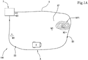
- the system 100 comprises a lawn mower 1 and a cutting area A delimiting the area in which the lawn mower performs the cutting.
- the movement of the lawn mower 1 takes place in proximity to the cutting area A, without excluding the possibility of it being outside the latter under particular conditions.
- the system further comprises a perimeter cable 2, delimiting the cutting area A, in which a perimeter electrical signal ES is propagated.
- the cutting area A comprises at least one main area AP.
- the lawn mower 1 comprises movement means 20 for moving the lawn mower 1 in the cutting area A and one or more blades for cutting the grass in the cutting area A.
- MSi for signalling
- the signalling means MSi can be in a number of one or a plurality.
- the means MSi for signalling a path change ⁇ Pi is configured to signal to the lawn mower a path change ⁇ Pi 1 relative to a predefined path PPRED provided for by the predefined operation of the lawn mower 1.
- the predefined path PPRED can be the trajectory defined in the granted European patent no. 2 502 482 under the name of the same applicant, i.e. an arced path, or the one described in European patent application no. 12154174.2 under the name of the same applicant, i.e. movement along lines parallel to the perimeter cable 2, or others.
- the signalling means MSi defines for the lawn mower 1, via the path change ⁇ Pi, at least one portion of an optimal path POPT for reaching a target point O relative to said predefined path PPRED.
- the optimal path for reaching the target point O thus comprises predefined path sections PPRED and path change sections ⁇ Pi.
- the means MSi for signalling a path change ⁇ Pi is configured to be movable within said cutting area A, in order to define a new optimal path POPT as a function of a modification of the target point O.
- the target point O comprises a recharging base 3 for the lawn mower 1 positioned in the cutting area A.
- the recharging base 3 can be outside or inside the cutting area A or positioned on the perimeter cable 2.
- the technical effect obtained with the capability of the signalling means MSi to be moved is an extreme flexibility in configuring the signals in the cutting area, which enables new obstacles to be identified with extreme ease so as to ensure that the operation of the lawn mower during cutting is in no way obstructed.
- Examples of obstacles can be an abrupt slope, a hole, the beginning of a bottleneck, surface roots, etc; the obstacles OST 1 and OST2 are schematically shown in figures 1b and 1C .
- the signalling means MSi is powered by an electromotive force fem induced by a magnetic field B generated on the basis of the perimeter electrical signal ES.
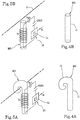
- a current varying over time which flows in the perimeter cable 2, determines a corresponding magnetic field B, which determines an induced electromotive force fem in the signalling means MSi, as shown in figures 5A and 5B .
- the pattern of the signal in the perimeter cable is, for example, as shown in the granted European patent no. 2 545 758 of the same applicant, in particular sinusoidal.
- the signalling means MSi is made of ferromagnetic material.
- the signalling means comprises a winding around a ferrite core.
- the signalling means MSi comprises a capacitor COND configured to be charged through the induced electromotive force fem.
- the signalling means MSi further comprises an electronic circuit 10, which will be described more in detail below.
- the means MSi for signalling a path change ⁇ Pi comprises a stem 11 and said signalling means is detached from the perimeter cable 2.
- the signalling means MSi is positioned in the cutting area, but not in contact with the perimeter cable 2.
- the signalling means MSi is positioned in contact with the perimeter cable 2.
- the signalling means MSi comprises the stem 11 and a hook-shaped head 12, preferably at one end of the stem 11, configured to surround the perimeter cable 2 in such a way as to define a physical contact between the signalling means MSi and the perimeter cable 2.
- the signalling means MSi comprises a meter for measuring the intensity B1 of the magnetic field B which powers it.
- the electronic circuit 10 is powered by an energy U stored by the capacitor COND as a result of the electromotive force induced by the magnetic field B.
- the electronic circuit 10 is configured to generate the encoded signals Si.
- the electronic circuit 10 comprises a generator G1 of the encoded signal Si.
- the technical effect obtained is the transmission, to the lawn mower, of information for travelling an optimized path which is minimized in terms of the energy required to transfer such information.
- the generator G1 is configured to generate the operational code Ci as a function of predefined minimum threshold values B11, B12 of the measured intensity B1.
- the generator G1 is configured to generate an operational code Ci corresponding to a simple path change function if the value of the magnetic field B11 ⁇ B ⁇ B12.
- threshold values are tied to distances from the perimeter cable serving to ensure reception of the field B; as an initial approximation, a maximum allowed distance of around 10 metres corresponds to the minimum value B11, whereas a maximum allowed distance of around 2.5 metres corresponds to the minimum value B12>B11.
- the signal Si emitted by the signalling means MSi will be "simpler" because the field B generated by the perimeter cable and sensed by the signalling means MSi is smaller (B11 ⁇ B ⁇ B12); the signal will be, for example, simply “turn right by 90°”, “turn left by 90°” etc..
- the technical effect obtained is an assurance of integrity of the signal Si transmitted to the lawn mower, since it is generated with sufficient energy to ensure the reception thereof by the lawn mower.
- the path change functions f ⁇ Pi comprise one or more among:
- the lawn mower 1 when the lawn mower 1 meets a signalling means MSi, the latter transmits to it the signal Si comprising the code Ci for instructing the lawn mower as to the path change necessary to avoid a possible obstacle/danger located on the predefined path.
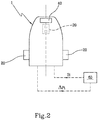
- the lawn mower 1 comprises, in addition to the previously described cutting and movement means, a sensor means 40 configured to sense the encoded signal Si.
- the sensor means 40 is situated in the front part of the lawn mower, i.e. in the same part where the recharging means exploited by the lawn mower upon its return to the recharging base is preferably also located.
- the lawn mower 1 further comprises a processing unit 60 associated with the sensor means 40.
- the processing unit 60 is configured to actuate the movement means 20 as a function of the sensed encoded signal Si, so that the movement means 20 are moved in order to cause the lawn mower 1 to make a path change ⁇ Pi.
- processing unit 60 will be presented as divided into distinct functional modules (memory modules or operating modules) for the sole purpose of describing the functions of the unit itself in a clear and complete manner.
- the processing unit can consist in a single electronic device (or circuit board), duly programmed to perform the functions described, and the various modules can correspond to hardware and/or routine software entities belonging to the programmed device
- Such functions may be performed by a plurality of electronic devices over which the aforesaid functional modules can be distributed
- the processing unit can moreover rely on one or more processors to execute the instructions contained in the memory modules.
- the functioning assured by the present invention is advantageous since the lawn mower autonomously knows how many there are and how far they are from the base because it meets the signalling means, positioned accordingly. This enables the lawn mower to avoid returning to the base in order to have a reference of the secondary area.
- the present invention further comprises a cutting optimization method implemented by the cutting optimization system described, wherein the lawn mower performs the steps of:
Landscapes
- Physics & Mathematics (AREA)
- Engineering & Computer Science (AREA)
- Life Sciences & Earth Sciences (AREA)
- Environmental Sciences (AREA)
- Electromagnetism (AREA)
- Aviation & Aerospace Engineering (AREA)
- Radar, Positioning & Navigation (AREA)
- Remote Sensing (AREA)
- General Physics & Mathematics (AREA)
- Automation & Control Theory (AREA)
- Harvester Elements (AREA)
Claims (17)
- System (100) zum Schneiden von Gras, umfassend:einen Rasenmäher (1), versehen mit:- Bewegungsmitteln (20) zum Bewegen des Rasenmähers (1) in einem Schneidbereich (A);- einem oder mehreren Messern (30) zum Schneiden von Gras in diesem Schneidbereich (A);ein umlaufendes Kabel (2), das den Schneidbereich (A) abgrenzt, in dem ein umlaufendes elektrisches Signal (ES) verbreitet wird;mindestens ein Mittel (MSi; i= 1...n) zum Signalisieren einer Wegänderung (ΔPi; i= 1...n), verbunden mit dem umlaufenden Kabel (2),- wobei das Mittel (MSi; i=1 ...n) zum Signalisieren einer Wegänderung (ΔPi; i= 1...n) ausgelegt ist, um dem Rasenmäher (1) eine Wegänderung (ΔPi) relativ zu einem vorgegebenen Weg (PPRED) zu melden, der vom vorgegebenen Betrieb des Rasenmähers (1) bereitgestellt wird,- wobei die Wegänderung (ΔPi) dem Rasenmäher mittels eines verschlüsselten Signals (Si; i=1...n) gemeldet wird, das vom Signalisierungsmittel (MSi; i= 1...n) generiert wird,- wobei das Signalisierungsmittel (MSi; i= 1...n) durch eine elektromotorische Kraft (fem) angetrieben wird, die durch ein Magnetfeld (B) induziert wird, das auf Basis des umlaufenden elektrischen Signals (ES) generiert wird,wobei der Rasenmäher (1) zudem umfasst:- Sensormittel (40), die ausgelegt sind, um das verschlüsselte Signal (Si) abzutasten;- eine Verarbeitungseinheit (60), die mit den Sensormitteln (40) verbunden und ausgelegt ist, um die Bewegungsmittel (20) als eine Funktion des abgetasteten verschlüsselten Signals (Si) zu betätigen, sodass die Bewegungsmittel (20) bewegt werden, um den Rasenmäher (1) zu veranlassen, die Wegänderung (ΔPi) durchzuführen,wobei das mindestens eine Signalisierungsmittel (MSi; i1...n) für den Rasenmäher (1) über die genannte Wegänderung (ΔPi) mindestens einen Abschnitt eines optimalen Wegs (POPT) definiert, um einen Zielpunkt (0) relativ zum vorgegebenen Weg (PPRED), der vom vorgegebenen Betrieb des Rasenmähers (1) bereitgestellt ist, zu erreichen,dadurch gekennzeichnet, dass
dieses Mittel (MSi; i=1...n) zum Signalisieren einer Wegänderung (ΔPi; i=1...n) ausgelegt ist, um innerhalb des Schneidbereichs (A) bewegbar zu sein und einen neuen optimalen Weg (POPT) als eine Funktion einer Änderung des Zielpunkts (0) zu definieren. - System nach Anspruch 1, wobei das Mittel (MSi; i=1...n) zum Signalisieren einer Wegänderung (ΔPi; i=1...n) einen elektronischen Kreislauf (10) umfasst, der ausgelegt ist, um das verschlüsselte Signal (Si; i=1...n) auszusenden.
- System nach einem der vorhergehenden Ansprüche, wobei das elektronische verschlüsselte Signal (Si) einen Betriebscode (Ci; 1...n) umfasst, der repräsentativ für eine spezielle Wegänderungsfunktion (fΔPi; i= 1...n) ist, die repräsentativ für eine Änderung des vorgegebenen Wegs des Rasenmähers (1) ist.
- System nach Anspruch 3, wobei die Verarbeitungseinheit (60) ein Speichermodul (63) umfasst, umfassend eine Übereinstimmung zwischen einem vorgegebenen Betriebscode (CPREDi; i=1...n) und der Wegänderungsfunktion (fΔPi; i= 1...n).
- System nach Anspruch 3 und 4, wobei die Verarbeitungseinheit (60) ein Vergleichsmodul (62) umfasst, das ausgelegt ist, um den Betriebscode (Ci; 1...n) mit dem vorgegebenen Betriebscode (CPREDi; i=1...n) zu vergleichen und eine entsprechende Wegänderungsfunktion (fΔPi; i= 1...n) zu definieren, sodass die Bewegungsmittel (20) bewegt werden, um den Rasenmäher (1) dazu zu veranlassen, die Wegänderung (ΔPi) durchzuführen.
- System nach einem der Ansprüche 3 bis 5, wobei die Wegänderungsfunktionen (fΔPi; i= 1...n) einen oder mehrere der folgenden Vorgänge umfassen:Durchführen eines entsprechenden Einfahrtsmanövers, wenn eine Ladestation (fΔPO) vorhanden ist;Wenden nach links oder rechts um einen vorgegebenen Winkel, um die schnellste Rückfahrtsstrecke zu erreichen, wenn ein gefährliches Hindernis (OST1, OST2) vorhanden ist (fΔP1); Beginnen des Schneidens in einem Nebenbereich (ASi; 1= 1..m) (fΔP2);nacheinander Drosseln der Geschwindigkeit, Wenden nach links oder rechts um einen vorgegebenen Winkel und Beschleunigen (fΔP3);nacheinander Anheben der Messer, Drosseln der Geschwindigkeit, Senken der Messer und Beschleunigen (fΔP4);oder Derartiges.
- System nach einem der vorhergehenden Ansprüche, wobei das Signalmittel (MSi; i= 1...n) ein Messgerät zum Messen der Stärke (B1) des Magnetfelds (B) umfasst, das das Signalmittel speist.
- System nach Anspruch 7, wobei der elektronische Kreislauf (10) einen Generator (G1) des verschlüsselten Signals (Si) umfasst, der ausgelegt ist, um den Betriebscode (Ci; i=1...n) als eine Funktion der gemessenen Stärke (B1) zu generieren.
- System nach Anspruch 8, wobei der Generator (G1) ausgelegt ist, um den Betriebscode (Ci; i=1...n) als eine Funktion vorgegebener Mindestschwellenwerte (B11, B12) der gemessenen Stärke (B1) zu generieren.
- System nach Anspruch 9, wobei der Generator (G1) ausgelegt ist, um zu generieren:einen Betriebscode (Ci), der einer detaillierten Wegänderungsfunktion (fΔPi; i= 1...n) entspricht, wenn der Wert des Magnetfelds (B) B>=B12 beträgt;einen Betriebscode (Ci), der einer einfachen Wegänderungsfunktion (fΔPi; i= 1...n) entspricht, wenn der Wert des Magnetfelds (B) B11<B<B12 beträgt.
- System nach einem der vorhergehenden Ansprüche, dadurch gekennzeichnet, dass mindestens ein Signalisierungsmittel (MSi; i= 1...n) aus ferromagnetischem Material besteht.
- System nach Anspruch 11, wobei das mindestens eine Signalisierungsmittel (MSi; i= 1...n) umfasst:einen Kondensator (COND), der ausgelegt ist, um durch die elektromotorische Kraft (fem) geladen zu werden,den elektronischen Kreislauf (10), gespeist durch eine entsprechende Energie (U), die vom Kondensator (COND) gespeichert wird, und ausgelegt, um die verschlüsselten Signale (Si) zu generieren.
- System nach einem der vorhergehenden Ansprüche, wobei das mindestens eine Mittel (MSi; i= 1...n) zum Signalisieren einer Wegänderung (ΔPi; i= 1...n) umfasst:einen Schaft (11);das mindestens eine Signalisierungsmittel, das vom umlaufenden Kabel (2) gelöst ist.
- System nach einem der Ansprüche 1 bis 12, wobei das mindestens eine Mittel (MSi; i= 1...n) zum Signalisieren einer Wegänderung (ΔPi; i= 1...n) mit dem umlaufenden Kabel (2) in Kontakt ist.
- System nach Anspruch 14, wobei das mindestens eine Mittel (MSi; i=1 ...n) zum Signalisieren einer Wegänderung (ΔPi; i=1 ...n) umfasst: einen Schaft (11); einen hakenförmigen Kopf (12), vorzugsweise an einem Ende des Schafts (11), ausgelegt, um das umlaufende Kabel (2) zu umgeben, sodass ein materieller Kontakt zwischen dem Signalisierungsmittel (MSi; i= 1...n) und dem umlaufenden Kabel (2) definiert wird.
- System nach einem der vorhergehenden Ansprüche, wobei der Schneidbereich (A) mindestens einen Hauptbereich (AP) und mindestens einen Nebenbereich (ASi; i=1..m) umfasst, die möglichst aneinandergrenzen und durch mindestens das umlaufende Kabel (2) abgegrenzt sind.
- Schneidverbesserungsverfahren, implementiert durch das System für ein verbessertes Schneiden nach den vorhergehenden Ansprüchen, umfassend die folgenden Schritte, die durch den Rasenmäher (1) in einem Schneidbereich (A) implementiert werden:Bewegen entlang des umlaufenden Kabels (2), das den Schneidbereich (A) abgrenzt, um den Zielpunkt (0) zu erreichen;Treffen auf das mindestens eine Signalisierungsmittel (MSi; i=1...n);Empfangen eines verschlüsselten Signals (Si) vom Signalisierungsmittel (MSi; i=1...n);Folgen einer Wegänderung (ΔPi; i=1..n) relativ zu einem vorgegebenen Weg (PPRED) auf Basis des empfangenen Signals (Si; i=1..n), wobei das mindestens eine Signalisierungsmittel (MSi; i=1...n) für den Rasenmäher (1)über die Wegänderung (ΔPi) mindestens einen Abschnitt eines optimalen Wegs (POPT) definiert, um einen Zielpunkt (0) relativ zum vorgegebenen Weg (PPRED) zu erreichen, der durch den vorgegebenen Betrieb des Rasenmähers (1) bereitgestellt ist, wobei das Signalisierungsmittel (MSi; i=1...n) ausgelegt ist, um innerhalb eines Schneidbereichs (A) bewegt zu werden und einen neuen optimalen Weg (POPT) als eine Funktion einer Änderung des Zielpunkts (0) zu definieren.
Applications Claiming Priority (1)
| Application Number | Priority Date | Filing Date | Title |
|---|---|---|---|
| ITMI20141622 | 2014-09-19 |
Publications (2)
| Publication Number | Publication Date |
|---|---|
| EP2997808A1 EP2997808A1 (de) | 2016-03-23 |
| EP2997808B1 true EP2997808B1 (de) | 2017-04-26 |
Family
ID=51904052
Family Applications (1)
| Application Number | Title | Priority Date | Filing Date |
|---|---|---|---|
| EP15177371.0A Active EP2997808B1 (de) | 2014-09-19 | 2015-07-17 | System für ein verbessertes schneiden von grass |
Country Status (1)
| Country | Link |
|---|---|
| EP (1) | EP2997808B1 (de) |
Cited By (1)
| Publication number | Priority date | Publication date | Assignee | Title |
|---|---|---|---|---|
| WO2019096264A1 (zh) * | 2017-11-16 | 2019-05-23 | 南京德朔实业有限公司 | 智能割草系统 |
Families Citing this family (4)
| Publication number | Priority date | Publication date | Assignee | Title |
|---|---|---|---|---|
| SE540576C2 (en) * | 2017-04-25 | 2018-10-02 | Husqvarna Ab | Compensating for stray capacitances for a robotic lawnmower |
| SE542736C2 (en) * | 2017-04-25 | 2020-06-30 | Husqvarna Ab | Adaptive signal reception |
| IT201900007467A1 (it) * | 2019-05-29 | 2020-11-29 | Fabrizio Bernini | Sistema per la manutenzione di un manto erboso |
| CN113848873A (zh) * | 2020-06-28 | 2021-12-28 | 苏州宝时得电动工具有限公司 | 自移动设备及其工作方法 |
Family Cites Families (7)
| Publication number | Priority date | Publication date | Assignee | Title |
|---|---|---|---|---|
| SE0201740D0 (sv) * | 2002-06-07 | 2002-06-07 | Electrolux Ab | Electroniskt diregeringssystem |
| US8433468B2 (en) * | 2010-07-28 | 2013-04-30 | Deere & Company | Robotic mower home finding system |
| DE202010008800U1 (de) | 2010-10-13 | 2012-01-19 | Robocut Gmbh | Führungssystem für steuerbare Fahrzeuge |
| EP2502482B1 (de) | 2011-03-23 | 2013-05-22 | Fabrizio Bernini | Mähvorrichtung |
| EP2545758B1 (de) | 2011-07-14 | 2013-10-30 | Fabrizio Bernini | Vorrichtung zum Abschneiden von Gras |
| EP2679083B1 (de) * | 2012-06-27 | 2015-08-05 | Fabrizio Bernini | Mähvorrichtung |
| EP2959348B1 (de) * | 2013-02-20 | 2018-09-19 | Husqvarna AB | Robotisches arbeitswerkzeugsystem und -verfahren mit einer ladestation |
-
2015
- 2015-07-17 EP EP15177371.0A patent/EP2997808B1/de active Active
Non-Patent Citations (1)
| Title |
|---|
| None * |
Cited By (2)
| Publication number | Priority date | Publication date | Assignee | Title |
|---|---|---|---|---|
| WO2019096264A1 (zh) * | 2017-11-16 | 2019-05-23 | 南京德朔实业有限公司 | 智能割草系统 |
| US11076529B2 (en) | 2017-11-16 | 2021-08-03 | Nanjing Chervon Industry Co., Ltd. | Intelligent mowing system |
Also Published As
| Publication number | Publication date |
|---|---|
| EP2997808A1 (de) | 2016-03-23 |
Similar Documents
| Publication | Publication Date | Title |
|---|---|---|
| EP2997808B1 (de) | System für ein verbessertes schneiden von grass | |
| EP3599813B1 (de) | Robotermäher und verfahren zur steuerung eines robotermähers | |
| EP2625946B1 (de) | Vorrichtung zum Schneiden von Gras | |
| US11415998B2 (en) | System and method for docking a robotic mower | |
| CN108142070B (zh) | 自动割草系统及其控制方法 | |
| CN115279170B (zh) | 一种自动工作系统 | |
| EP3324261B1 (de) | Automatischer rasenmäherroboter und zugehöriges steuerungsverfahren | |
| US8306659B2 (en) | Autonomous robot | |
| US8838291B2 (en) | Communication and safety device for boundary aided systems | |
| EP2829937B1 (de) | Roboter-Arbeitsgerät für einen begrenzten Arbeitsbereich | |
| EP2558918B1 (de) | Robotisches gartenwerkzeug mit drahtverfolgung in einer bestimmten distanz anhand von mehreren signalen | |
| EP2939513B1 (de) | Rasenmäherroboter und Steuerungsverfahren dafür | |
| US20210204473A1 (en) | Autonomous lawnmower and steering method thereof | |
| EP2502482B1 (de) | Mähvorrichtung | |
| CN112486157B (zh) | 自动工作系统及其转向方法、自移动设备 | |
| EP2679083B1 (de) | Mähvorrichtung | |
| CN106444736B (zh) | 自动返回系统及控制方法 | |
| CN109765899A (zh) | 自移动机器人系统 | |
| KR20130061962A (ko) | 잔디 깍기의 경계 인식 시스템 | |
| CN115328107A (zh) | 智能割草系统及智能割草设备 | |
| CN117898106B (zh) | 智能割草机 | |
| EP2641460B1 (de) | Vorrichtung zum Schneiden von Gras | |
| SE2151613A1 (en) | Improved navigation for a robotic work tool system | |
| SE546034C2 (en) | Improved navigation for a robotic work tool system | |
| CN113534800A (zh) | 一种循迹控制方法、自动行走设备及可读存储介质 |
Legal Events
| Date | Code | Title | Description |
|---|---|---|---|
| PUAI | Public reference made under article 153(3) epc to a published international application that has entered the european phase |
Free format text: ORIGINAL CODE: 0009012 |
|
| AK | Designated contracting states |
Kind code of ref document: A1 Designated state(s): AL AT BE BG CH CY CZ DE DK EE ES FI FR GB GR HR HU IE IS IT LI LT LU LV MC MK MT NL NO PL PT RO RS SE SI SK SM TR |
|
| AX | Request for extension of the european patent |
Extension state: BA ME |
|
| 17P | Request for examination filed |
Effective date: 20160915 |
|
| RBV | Designated contracting states (corrected) |
Designated state(s): AL AT BE BG CH CY CZ DE DK EE ES FI FR GB GR HR HU IE IS IT LI LT LU LV MC MK MT NL NO PL PT RO RS SE SI SK SM TR |
|
| GRAP | Despatch of communication of intention to grant a patent |
Free format text: ORIGINAL CODE: EPIDOSNIGR1 |
|
| INTG | Intention to grant announced |
Effective date: 20170215 |
|
| GRAS | Grant fee paid |
Free format text: ORIGINAL CODE: EPIDOSNIGR3 |
|
| GRAA | (expected) grant |
Free format text: ORIGINAL CODE: 0009210 |
|
| AK | Designated contracting states |
Kind code of ref document: B1 Designated state(s): AL AT BE BG CH CY CZ DE DK EE ES FI FR GB GR HR HU IE IS IT LI LT LU LV MC MK MT NL NO PL PT RO RS SE SI SK SM TR |
|
| REG | Reference to a national code |
Ref country code: GB Ref legal event code: FG4D |
|
| REG | Reference to a national code |
Ref country code: CH Ref legal event code: EP |
|
| REG | Reference to a national code |
Ref country code: AT Ref legal event code: REF Ref document number: 887070 Country of ref document: AT Kind code of ref document: T Effective date: 20170515 |
|
| REG | Reference to a national code |
Ref country code: IE Ref legal event code: FG4D |
|
| REG | Reference to a national code |
Ref country code: DE Ref legal event code: R096 Ref document number: 602015002395 Country of ref document: DE |
|
| REG | Reference to a national code |
Ref country code: NL Ref legal event code: MP Effective date: 20170426 |
|
| REG | Reference to a national code |
Ref country code: LT Ref legal event code: MG4D |
|
| REG | Reference to a national code |
Ref country code: AT Ref legal event code: MK05 Ref document number: 887070 Country of ref document: AT Kind code of ref document: T Effective date: 20170426 |
|
| PG25 | Lapsed in a contracting state [announced via postgrant information from national office to epo] |
Ref country code: NL Free format text: LAPSE BECAUSE OF FAILURE TO SUBMIT A TRANSLATION OF THE DESCRIPTION OR TO PAY THE FEE WITHIN THE PRESCRIBED TIME-LIMIT Effective date: 20170426 |
|
| PG25 | Lapsed in a contracting state [announced via postgrant information from national office to epo] |
Ref country code: AT Free format text: LAPSE BECAUSE OF FAILURE TO SUBMIT A TRANSLATION OF THE DESCRIPTION OR TO PAY THE FEE WITHIN THE PRESCRIBED TIME-LIMIT Effective date: 20170426 Ref country code: ES Free format text: LAPSE BECAUSE OF FAILURE TO SUBMIT A TRANSLATION OF THE DESCRIPTION OR TO PAY THE FEE WITHIN THE PRESCRIBED TIME-LIMIT Effective date: 20170426 Ref country code: HR Free format text: LAPSE BECAUSE OF FAILURE TO SUBMIT A TRANSLATION OF THE DESCRIPTION OR TO PAY THE FEE WITHIN THE PRESCRIBED TIME-LIMIT Effective date: 20170426 Ref country code: LT Free format text: LAPSE BECAUSE OF FAILURE TO SUBMIT A TRANSLATION OF THE DESCRIPTION OR TO PAY THE FEE WITHIN THE PRESCRIBED TIME-LIMIT Effective date: 20170426 Ref country code: NO Free format text: LAPSE BECAUSE OF FAILURE TO SUBMIT A TRANSLATION OF THE DESCRIPTION OR TO PAY THE FEE WITHIN THE PRESCRIBED TIME-LIMIT Effective date: 20170726 Ref country code: FI Free format text: LAPSE BECAUSE OF FAILURE TO SUBMIT A TRANSLATION OF THE DESCRIPTION OR TO PAY THE FEE WITHIN THE PRESCRIBED TIME-LIMIT Effective date: 20170426 Ref country code: GR Free format text: LAPSE BECAUSE OF FAILURE TO SUBMIT A TRANSLATION OF THE DESCRIPTION OR TO PAY THE FEE WITHIN THE PRESCRIBED TIME-LIMIT Effective date: 20170727 |
|
| PG25 | Lapsed in a contracting state [announced via postgrant information from national office to epo] |
Ref country code: IS Free format text: LAPSE BECAUSE OF FAILURE TO SUBMIT A TRANSLATION OF THE DESCRIPTION OR TO PAY THE FEE WITHIN THE PRESCRIBED TIME-LIMIT Effective date: 20170826 Ref country code: RS Free format text: LAPSE BECAUSE OF FAILURE TO SUBMIT A TRANSLATION OF THE DESCRIPTION OR TO PAY THE FEE WITHIN THE PRESCRIBED TIME-LIMIT Effective date: 20170426 Ref country code: SE Free format text: LAPSE BECAUSE OF FAILURE TO SUBMIT A TRANSLATION OF THE DESCRIPTION OR TO PAY THE FEE WITHIN THE PRESCRIBED TIME-LIMIT Effective date: 20170426 Ref country code: LV Free format text: LAPSE BECAUSE OF FAILURE TO SUBMIT A TRANSLATION OF THE DESCRIPTION OR TO PAY THE FEE WITHIN THE PRESCRIBED TIME-LIMIT Effective date: 20170426 Ref country code: PL Free format text: LAPSE BECAUSE OF FAILURE TO SUBMIT A TRANSLATION OF THE DESCRIPTION OR TO PAY THE FEE WITHIN THE PRESCRIBED TIME-LIMIT Effective date: 20170426 Ref country code: BG Free format text: LAPSE BECAUSE OF FAILURE TO SUBMIT A TRANSLATION OF THE DESCRIPTION OR TO PAY THE FEE WITHIN THE PRESCRIBED TIME-LIMIT Effective date: 20170726 |
|
| REG | Reference to a national code |
Ref country code: DE Ref legal event code: R097 Ref document number: 602015002395 Country of ref document: DE |
|
| PG25 | Lapsed in a contracting state [announced via postgrant information from national office to epo] |
Ref country code: RO Free format text: LAPSE BECAUSE OF FAILURE TO SUBMIT A TRANSLATION OF THE DESCRIPTION OR TO PAY THE FEE WITHIN THE PRESCRIBED TIME-LIMIT Effective date: 20170426 Ref country code: DK Free format text: LAPSE BECAUSE OF FAILURE TO SUBMIT A TRANSLATION OF THE DESCRIPTION OR TO PAY THE FEE WITHIN THE PRESCRIBED TIME-LIMIT Effective date: 20170426 Ref country code: CZ Free format text: LAPSE BECAUSE OF FAILURE TO SUBMIT A TRANSLATION OF THE DESCRIPTION OR TO PAY THE FEE WITHIN THE PRESCRIBED TIME-LIMIT Effective date: 20170426 Ref country code: SK Free format text: LAPSE BECAUSE OF FAILURE TO SUBMIT A TRANSLATION OF THE DESCRIPTION OR TO PAY THE FEE WITHIN THE PRESCRIBED TIME-LIMIT Effective date: 20170426 Ref country code: EE Free format text: LAPSE BECAUSE OF FAILURE TO SUBMIT A TRANSLATION OF THE DESCRIPTION OR TO PAY THE FEE WITHIN THE PRESCRIBED TIME-LIMIT Effective date: 20170426 |
|
| PG25 | Lapsed in a contracting state [announced via postgrant information from national office to epo] |
Ref country code: SM Free format text: LAPSE BECAUSE OF FAILURE TO SUBMIT A TRANSLATION OF THE DESCRIPTION OR TO PAY THE FEE WITHIN THE PRESCRIBED TIME-LIMIT Effective date: 20170426 |
|
| PLBE | No opposition filed within time limit |
Free format text: ORIGINAL CODE: 0009261 |
|
| STAA | Information on the status of an ep patent application or granted ep patent |
Free format text: STATUS: NO OPPOSITION FILED WITHIN TIME LIMIT |
|
| 26N | No opposition filed |
Effective date: 20180129 |
|
| REG | Reference to a national code |
Ref country code: IE Ref legal event code: MM4A |
|
| REG | Reference to a national code |
Ref country code: FR Ref legal event code: ST Effective date: 20180330 |
|
| PG25 | Lapsed in a contracting state [announced via postgrant information from national office to epo] |
Ref country code: IE Free format text: LAPSE BECAUSE OF NON-PAYMENT OF DUE FEES Effective date: 20170717 |
|
| REG | Reference to a national code |
Ref country code: BE Ref legal event code: MM Effective date: 20170731 |
|
| PG25 | Lapsed in a contracting state [announced via postgrant information from national office to epo] |
Ref country code: SI Free format text: LAPSE BECAUSE OF FAILURE TO SUBMIT A TRANSLATION OF THE DESCRIPTION OR TO PAY THE FEE WITHIN THE PRESCRIBED TIME-LIMIT Effective date: 20170426 Ref country code: FR Free format text: LAPSE BECAUSE OF NON-PAYMENT OF DUE FEES Effective date: 20170731 |
|
| PG25 | Lapsed in a contracting state [announced via postgrant information from national office to epo] |
Ref country code: LU Free format text: LAPSE BECAUSE OF NON-PAYMENT OF DUE FEES Effective date: 20170717 |
|
| PG25 | Lapsed in a contracting state [announced via postgrant information from national office to epo] |
Ref country code: BE Free format text: LAPSE BECAUSE OF NON-PAYMENT OF DUE FEES Effective date: 20170731 |
|
| PG25 | Lapsed in a contracting state [announced via postgrant information from national office to epo] |
Ref country code: MT Free format text: LAPSE BECAUSE OF NON-PAYMENT OF DUE FEES Effective date: 20170717 |
|
| REG | Reference to a national code |
Ref country code: CH Ref legal event code: PL |
|
| PG25 | Lapsed in a contracting state [announced via postgrant information from national office to epo] |
Ref country code: CH Free format text: LAPSE BECAUSE OF NON-PAYMENT OF DUE FEES Effective date: 20180731 Ref country code: LI Free format text: LAPSE BECAUSE OF NON-PAYMENT OF DUE FEES Effective date: 20180731 |
|
| PG25 | Lapsed in a contracting state [announced via postgrant information from national office to epo] |
Ref country code: HU Free format text: LAPSE BECAUSE OF FAILURE TO SUBMIT A TRANSLATION OF THE DESCRIPTION OR TO PAY THE FEE WITHIN THE PRESCRIBED TIME-LIMIT; INVALID AB INITIO Effective date: 20150717 Ref country code: MC Free format text: LAPSE BECAUSE OF FAILURE TO SUBMIT A TRANSLATION OF THE DESCRIPTION OR TO PAY THE FEE WITHIN THE PRESCRIBED TIME-LIMIT Effective date: 20170426 |
|
| PG25 | Lapsed in a contracting state [announced via postgrant information from national office to epo] |
Ref country code: CY Free format text: LAPSE BECAUSE OF FAILURE TO SUBMIT A TRANSLATION OF THE DESCRIPTION OR TO PAY THE FEE WITHIN THE PRESCRIBED TIME-LIMIT Effective date: 20170426 |
|
| PG25 | Lapsed in a contracting state [announced via postgrant information from national office to epo] |
Ref country code: MK Free format text: LAPSE BECAUSE OF FAILURE TO SUBMIT A TRANSLATION OF THE DESCRIPTION OR TO PAY THE FEE WITHIN THE PRESCRIBED TIME-LIMIT Effective date: 20170426 |
|
| PGFP | Annual fee paid to national office [announced via postgrant information from national office to epo] |
Ref country code: DE Payment date: 20190930 Year of fee payment: 5 |
|
| GBPC | Gb: european patent ceased through non-payment of renewal fee |
Effective date: 20190717 |
|
| PG25 | Lapsed in a contracting state [announced via postgrant information from national office to epo] |
Ref country code: TR Free format text: LAPSE BECAUSE OF FAILURE TO SUBMIT A TRANSLATION OF THE DESCRIPTION OR TO PAY THE FEE WITHIN THE PRESCRIBED TIME-LIMIT Effective date: 20170426 |
|
| PG25 | Lapsed in a contracting state [announced via postgrant information from national office to epo] |
Ref country code: GB Free format text: LAPSE BECAUSE OF NON-PAYMENT OF DUE FEES Effective date: 20190717 |
|
| PG25 | Lapsed in a contracting state [announced via postgrant information from national office to epo] |
Ref country code: PT Free format text: LAPSE BECAUSE OF FAILURE TO SUBMIT A TRANSLATION OF THE DESCRIPTION OR TO PAY THE FEE WITHIN THE PRESCRIBED TIME-LIMIT Effective date: 20170426 |
|
| PG25 | Lapsed in a contracting state [announced via postgrant information from national office to epo] |
Ref country code: AL Free format text: LAPSE BECAUSE OF FAILURE TO SUBMIT A TRANSLATION OF THE DESCRIPTION OR TO PAY THE FEE WITHIN THE PRESCRIBED TIME-LIMIT Effective date: 20170426 |
|
| REG | Reference to a national code |
Ref country code: DE Ref legal event code: R119 Ref document number: 602015002395 Country of ref document: DE |
|
| PG25 | Lapsed in a contracting state [announced via postgrant information from national office to epo] |
Ref country code: DE Free format text: LAPSE BECAUSE OF NON-PAYMENT OF DUE FEES Effective date: 20210202 |
|
| PGFP | Annual fee paid to national office [announced via postgrant information from national office to epo] |
Ref country code: IT Payment date: 20240723 Year of fee payment: 10 |