EP2998077A2 - Robotersystem, robotervorrichtung und verfahren zum aufnehmen eines werkstücks - Google Patents
Robotersystem, robotervorrichtung und verfahren zum aufnehmen eines werkstücks Download PDFInfo
- Publication number
- EP2998077A2 EP2998077A2 EP15183826.5A EP15183826A EP2998077A2 EP 2998077 A2 EP2998077 A2 EP 2998077A2 EP 15183826 A EP15183826 A EP 15183826A EP 2998077 A2 EP2998077 A2 EP 2998077A2
- Authority
- EP
- European Patent Office
- Prior art keywords
- workpiece
- conveyor
- robot
- workpieces
- missing
- Prior art date
- Legal status (The legal status is an assumption and is not a legal conclusion. Google has not performed a legal analysis and makes no representation as to the accuracy of the status listed.)
- Granted
Links
Images




Classifications
-
- B—PERFORMING OPERATIONS; TRANSPORTING
- B65—CONVEYING; PACKING; STORING; HANDLING THIN OR FILAMENTARY MATERIAL
- B65G—TRANSPORT OR STORAGE DEVICES, e.g. CONVEYORS FOR LOADING OR TIPPING, SHOP CONVEYOR SYSTEMS OR PNEUMATIC TUBE CONVEYORS
- B65G47/00—Article or material-handling devices associated with conveyors; Methods employing such devices
- B65G47/74—Feeding, transfer, or discharging devices of particular kinds or types
- B65G47/90—Devices for picking-up and depositing articles or materials
- B65G47/905—Control arrangements
-
- B—PERFORMING OPERATIONS; TRANSPORTING
- B25—HAND TOOLS; PORTABLE POWER-DRIVEN TOOLS; MANIPULATORS
- B25J—MANIPULATORS; CHAMBERS PROVIDED WITH MANIPULATION DEVICES
- B25J9/00—Program-controlled manipulators
- B25J9/16—Program controls
-
- B—PERFORMING OPERATIONS; TRANSPORTING
- B25—HAND TOOLS; PORTABLE POWER-DRIVEN TOOLS; MANIPULATORS
- B25J—MANIPULATORS; CHAMBERS PROVIDED WITH MANIPULATION DEVICES
- B25J9/00—Program-controlled manipulators
- B25J9/0093—Program-controlled manipulators co-operating with conveyor means
-
- B—PERFORMING OPERATIONS; TRANSPORTING
- B25—HAND TOOLS; PORTABLE POWER-DRIVEN TOOLS; MANIPULATORS
- B25J—MANIPULATORS; CHAMBERS PROVIDED WITH MANIPULATION DEVICES
- B25J9/00—Program-controlled manipulators
- B25J9/16—Program controls
- B25J9/1679—Program controls characterised by the tasks executed
-
- B—PERFORMING OPERATIONS; TRANSPORTING
- B25—HAND TOOLS; PORTABLE POWER-DRIVEN TOOLS; MANIPULATORS
- B25J—MANIPULATORS; CHAMBERS PROVIDED WITH MANIPULATION DEVICES
- B25J9/00—Program-controlled manipulators
- B25J9/16—Program controls
- B25J9/1694—Program controls characterised by use of sensors other than normal servo-feedback from position, speed or acceleration sensors, perception control, multi-sensor controlled systems, sensor fusion
- B25J9/1697—Vision controlled systems
-
- B—PERFORMING OPERATIONS; TRANSPORTING
- B65—CONVEYING; PACKING; STORING; HANDLING THIN OR FILAMENTARY MATERIAL
- B65G—TRANSPORT OR STORAGE DEVICES, e.g. CONVEYORS FOR LOADING OR TIPPING, SHOP CONVEYOR SYSTEMS OR PNEUMATIC TUBE CONVEYORS
- B65G43/00—Control devices, e.g. for safety, warning or fault-correcting
- B65G43/08—Control devices operated by article or material being fed, conveyed or discharged
-
- B—PERFORMING OPERATIONS; TRANSPORTING
- B65—CONVEYING; PACKING; STORING; HANDLING THIN OR FILAMENTARY MATERIAL
- B65G—TRANSPORT OR STORAGE DEVICES, e.g. CONVEYORS FOR LOADING OR TIPPING, SHOP CONVEYOR SYSTEMS OR PNEUMATIC TUBE CONVEYORS
- B65G47/00—Article or material-handling devices associated with conveyors; Methods employing such devices
- B65G47/52—Devices for transferring articles or materials between conveyors i.e. discharging or feeding devices
-
- G—PHYSICS
- G05—CONTROLLING; REGULATING
- G05B—CONTROL OR REGULATING SYSTEMS IN GENERAL; FUNCTIONAL ELEMENTS OF SUCH SYSTEMS; MONITORING OR TESTING ARRANGEMENTS FOR SUCH SYSTEMS OR ELEMENTS
- G05B19/00—Program-control systems
- G05B19/02—Program-control systems electric
- G05B19/418—Total factory control, i.e. centrally controlling a plurality of machines, e.g. direct or distributed numerical control [DNC], flexible manufacturing systems [FMS], integrated manufacturing systems [IMS] or computer integrated manufacturing [CIM]
- G05B19/41815—Total factory control, i.e. centrally controlling a plurality of machines, e.g. direct or distributed numerical control [DNC], flexible manufacturing systems [FMS], integrated manufacturing systems [IMS] or computer integrated manufacturing [CIM] characterised by the cooperation between machine tools, manipulators and conveyor or other workpiece supply system, workcell
-
- G—PHYSICS
- G05—CONTROLLING; REGULATING
- G05B—CONTROL OR REGULATING SYSTEMS IN GENERAL; FUNCTIONAL ELEMENTS OF SUCH SYSTEMS; MONITORING OR TESTING ARRANGEMENTS FOR SUCH SYSTEMS OR ELEMENTS
- G05B19/00—Program-control systems
- G05B19/02—Program-control systems electric
- G05B19/418—Total factory control, i.e. centrally controlling a plurality of machines, e.g. direct or distributed numerical control [DNC], flexible manufacturing systems [FMS], integrated manufacturing systems [IMS] or computer integrated manufacturing [CIM]
- G05B19/41815—Total factory control, i.e. centrally controlling a plurality of machines, e.g. direct or distributed numerical control [DNC], flexible manufacturing systems [FMS], integrated manufacturing systems [IMS] or computer integrated manufacturing [CIM] characterised by the cooperation between machine tools, manipulators and conveyor or other workpiece supply system, workcell
- G05B19/4182—Total factory control, i.e. centrally controlling a plurality of machines, e.g. direct or distributed numerical control [DNC], flexible manufacturing systems [FMS], integrated manufacturing systems [IMS] or computer integrated manufacturing [CIM] characterised by the cooperation between machine tools, manipulators and conveyor or other workpiece supply system, workcell manipulators and conveyor only
-
- G—PHYSICS
- G05—CONTROLLING; REGULATING
- G05B—CONTROL OR REGULATING SYSTEMS IN GENERAL; FUNCTIONAL ELEMENTS OF SUCH SYSTEMS; MONITORING OR TESTING ARRANGEMENTS FOR SUCH SYSTEMS OR ELEMENTS
- G05B2219/00—Program-control systems
- G05B2219/30—Nc systems
- G05B2219/39—Robotics, robotics to robotics hand
- G05B2219/39102—Manipulator cooperating with conveyor
-
- Y—GENERAL TAGGING OF NEW TECHNOLOGICAL DEVELOPMENTS; GENERAL TAGGING OF CROSS-SECTIONAL TECHNOLOGIES SPANNING OVER SEVERAL SECTIONS OF THE IPC; TECHNICAL SUBJECTS COVERED BY FORMER USPC CROSS-REFERENCE ART COLLECTIONS [XRACs] AND DIGESTS
- Y02—TECHNOLOGIES OR APPLICATIONS FOR MITIGATION OR ADAPTATION AGAINST CLIMATE CHANGE
- Y02P—CLIMATE CHANGE MITIGATION TECHNOLOGIES IN THE PRODUCTION OR PROCESSING OF GOODS
- Y02P90/00—Enabling technologies with a potential contribution to greenhouse gas [GHG] emissions mitigation
- Y02P90/02—Total factory control, e.g. smart factories, flexible manufacturing systems [FMS] or integrated manufacturing systems [IMS]
-
- Y—GENERAL TAGGING OF NEW TECHNOLOGICAL DEVELOPMENTS; GENERAL TAGGING OF CROSS-SECTIONAL TECHNOLOGIES SPANNING OVER SEVERAL SECTIONS OF THE IPC; TECHNICAL SUBJECTS COVERED BY FORMER USPC CROSS-REFERENCE ART COLLECTIONS [XRACs] AND DIGESTS
- Y10—TECHNICAL SUBJECTS COVERED BY FORMER USPC
- Y10S—TECHNICAL SUBJECTS COVERED BY FORMER USPC CROSS-REFERENCE ART COLLECTIONS [XRACs] AND DIGESTS
- Y10S901/00—Robots
- Y10S901/02—Arm motion controller
Definitions
- the present invention relates to a robot system, a robot apparatus, and a method for picking a workpiece.
- Japanese Unexamined Patent Application Publication No. 2002-316716 discloses an object processor for use in a robot system in which conveyors or similar devices convey workpieces and robots hold the workpieces to transfer the workpieces to another place.
- the object processor includes first and second conveyors and first and second robots.
- the first and second conveyors convey objects in the same direction.
- the two robots transfer the objects from the first conveyor to the second conveyor.
- the first conveyor first conveys a random mixture of different kinds of workpieces. From among the different kinds of workpieces, the first robot holds a first kind of workpieces, one at a time in the order that the first kind of workpieces are conveyed; picks the first kind of workpieces from the first conveyor; and transfers the first kind of workpieces to the second conveyor.
- the second robot holds a second kind of workpieces, from among the different kinds of workpieces, that are intended to be combined with the first kind of workpieces in the order that the second kind of workpieces are conveyed; picks the second kind of workpieces from the first conveyor; transfers the second kind of workpieces to the second conveyor; and combines the second kind of workpieces with the first kind of workpieces.
- Japanese Unexamined Patent Application Publication No. 2002-316716 leaves room for improvement in effective transfer of the workpieces.
- the workpieces to be transferred are picked from the first conveyor in the order that the workpieces are conveyed.
- the first kind of workpieces continues on the first conveyor and there is no second kind of workpieces for the second robot to transfer to the second conveyor, there is a possibility of a flow of only the first kind of workpieces on the second conveyor. That is, there is a possibility of the first kind of workpieces lacking in combination with the second kind of workpieces.
- Japanese Unexamined Patent Application Publication No. 2002-316716 attends to this lack of combination by decelerating or stopping the second conveyor to wait for a combination to occur.
- the wait adds time to the already time-consuming transfer of the workpieces using the plurality of robots, to the detriment of efficiency.
- the present disclosure has been made in view of the above-described circumstances. It is an object of the present disclosure to provide a robot system, a robot apparatus, and a method for picking a workpiece that ensure more efficient transfer of workpieces.
- a robot system includes a first conveyor, a second conveyor, a robot, and a controller.
- the first conveyor is configured to convey a plurality of kinds of workpieces.
- the second conveyor is configured to convey workpiece groups each including a combination of the plurality of kinds of workpieces.
- the controller is configured to control the robot, and includes a situation acquirer, a determiner, and an instructor.
- the situation acquirer is configured to acquire a situation in a predetermined monitor area on the first conveyor and the second conveyor.
- the predetermined monitor area is set based on a movable range of the robot.
- the determiner is configured to determine whether at least one workpiece among the plurality of kinds of workpieces on the first conveyor in the predetermined monitor area is a missing workpiece of at least one workpiece group among the workpiece groups in the predetermined monitor area.
- the instructor is configured to instruct the robot to hold the at least one workpiece determined as the missing workpiece by the determiner and to transfer the at least one workpiece from the first conveyor to the second conveyor.
- the one embodiment ensures more efficient transfer of workpiece.
- picking the action of holding a workpiece conveyed on a conveyor and taking the workpiece from the conveyor.
- FIG. 1A is a schematic plan view of a robot system 1 according to the first embodiment, illustrating an arrangement configuration of the robot system 1.
- FIG. 1B is a schematic side view of a robot 30, illustrating a transfer movement of the robot 30.
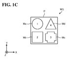
- FIG. 1C is a schematic plan view of exemplary workpieces W and an exemplary workpiece group WG.
- FIG. 1A illustrates a three-dimensional orthogonal coordinate system including a Z axis with its vertically upward direction being assumed the positive direction.
- This orthogonal coordinate system may also be illustrated in some other drawings referred to in the following description.
- the robot system 1 includes a first conveyor 10 (corresponding to the first conveyor), a second conveyor 20 (corresponding to the second conveyor), the robot 30, a detector 40, and a controller 50.
- the first conveyor 10 is a conveyance device that conveys, from the upstream side toward the downstream side, a plurality of kinds of workpieces W mixed together at random.
- the second conveyor 20 is a conveyance device that conveys workpiece groups WG from the upstream side toward the downstream side. Each of the workpiece groups WG is a combination of the plurality of kinds of workpieces W.
- the first conveyor 10 and the second conveyor 20 are belt conveyors. This configuration, however, should not be construed in a limiting sense.
- the first conveyor 10 and the second conveyor 20 may be any other conveyance devices insofar as the conveyance devices are capable of conveying the workpieces W and the workpiece groups WG in a predetermined conveyance direction.
- the conveyance direction is the negative direction of the X axis.
- the first conveyor 10 and the second conveyor 20 are arranged to pass through the movable range of the robot 30.
- a monitor area GR is set based on the movable range of the robot 30 on the conveyance paths of the first conveyor 10 and the second conveyor 20.
- the robot 30 is an articulated robot secured on an installation object such as a ceiling, a wall, and a floor.
- the robot 30 is a parallel link robot with its base secured on a ceiling.
- the robot 30 picks a plurality of kinds of workpieces W, one at a time, conveyed on the first conveyor 10 (see the arrow 101 in FIG. 1B ), and transfers the workpieces W to the second conveyor 20 successively (see the arrow 102 in FIG. 1B ). Then, the robot 30 successively places the workpieces W on, for example, pallets P conveyed on the second conveyor 20 (see the arrow 103 in FIG. 1B ). Thus, the robot 30 combines the plurality of kinds of workpieces W and generates workpiece groups WG.
- the robot 30 includes an arm 31. At the distal end of the arm 31, a holder 32 is attached so as to hold a workpiece W.
- the holder 32 holds the workpiece W by sucking the workpiece W using a suction device such as a vacuum pump.
- the holder 32 moves the workpiece W to above the pallet P, and releases the suction force of the suction device.
- the robot 30 transfers the workpiece W from the first conveyor 10 to the second conveyor 20.
- the robot 30 is allowed to transfer the workpieces W in the monitor area GR.
- the robot 30 includes the single holder 32. This configuration, however, should not be construed in a limiting sense.
- the robot 30 may include two or more holders 32.
- the holder 32 may hold the workpiece W by other than suction.
- the holder 32 may clamp an end portion of the workpiece W.
- the robot 30 is a parallel link robot. This configuration, however, should not be construed in a limiting sense. Insofar as the robot 30 is capable of holding and transferring the workpiece W, the robot 30 may be a vertical articulated robot, a horizontal articulated robot, an orthogonal robot, or any other robot.
- the detector 40 is disposed at a further upstream position than the robot 30, and detects situations that the first conveyor 10 and the second conveyor 20 are in. As illustrated in FIG. 1A , the detector 40 includes, for example, a camera 41, photoelectric sensors 42, and encoders 43 (each corresponding to the measurer).
- the camera 41 picks up an image of predetermined imaging areas on the conveyance paths of the first conveyor 10 and the second conveyor 20 so as to detect conveyance situations of the workpieces W and the workpiece groups WG.
- Two photoelectric sensors 42 are dedicated to each of the first conveyor 10 and the second conveyor 20. The photoelectric sensors 42 emit and receive light to sense changes in the amount of received light, so as to detect conveyance situations of the workpieces W and the workpiece groups WG.
- One encoder 43 is dedicated to each of the first conveyor 10 and the second conveyor 20, and detects rotation situations of the first conveyor 10 and the second conveyor 20. Results of the detections performed by the camera 41, the photoelectric sensors 42, and the encoders 43 are output to the controller 50 through a communication network (not illustrated) such as Local Area Network (LAN).
- a communication network such as Local Area Network (LAN).
- the controller 50 is coupled in a communicable manner to various elements such as the first conveyor 10, the second conveyor 20, the robot 30, and the detector 40. It is noted that any form of connection, wired or wireless, may be employed.
- the controller 50 includes various control units, processors, and storages so as to control operations of the various elements coupled to the controller 50.
- the controller 50 For example, based on a job program acquired through an input device (such as a programming pendant), not illustrated, or through a higher device, the controller 50 generates a movement signal to cause the robot 30 to operate. Then, the controller 50 outputs the movement signal to the robot 30 to control the movement of the robot 30.
- an input device such as a programming pendant
- the controller 50 Based on a job program acquired through an input device (such as a programming pendant), not illustrated, or through a higher device, the controller 50 generates a movement signal to cause the robot 30 to operate. Then, the controller 50 outputs the movement signal to the robot 30 to control the movement of the robot 30.
- the movement signal is generated in the form of, for example, a pulse signal to each servomotor in each joint of the robot 30.
- a specific configuration of the controller 50 will be described later with reference to FIG. 4 .
- the detector 40 detects situations that the first conveyor 10 and the second conveyor 20. Based on the situations detected by the detector 40, the controller 50 acquires a situation in the monitor area GR.
- the controller 50 instructs the robot 30 to pick a workpiece W using the holder 32 and transfer the workpiece W from the first conveyor 10 to the second conveyor 20.
- the robot 30 performs the transfer movement.
- the robot system 1 selects a manner of picking that the robot system 1 determines as effective considering the situation in the monitor area GR, so as to eliminate or minimize a missed transfer to the second conveyor 20.
- the robot system 1 performs a more highly efficient transfer movement. This configuration will be described in more detail below with reference to FIG. 2 and later drawings.
- a workpiece group WG is generated by combining four kinds of workpieces Wa, Wb, Wc, and Wd on a pallet P.
- the workpieces Wa, Wb, Wc, and Wd are occasionally denoted with reference numerals.
- the reference numerals indicate the "transfer order”.
- the workpieces Wa, Wb, Wc, and Wd will be collectively referred to as "workpieces W”.
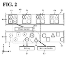
- FIG. 2 is a diagram illustrating the comparative method for picking a workpiece.
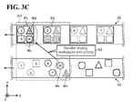
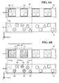
- FIGs. 3A to 3C are first to third diagrams illustrating the method according to the first embodiment for picking a workpiece.
- the elements used are identical to the elements used in the method according to the first embodiment, and like reference numerals designate corresponding or identical elements throughout FIGs. 2 to 3C for convenience of description.
- the workpieces W indicated by phantom lines are imaginary workpieces W
- the workpieces W indicated by solid lines are real workpieces W. That is, the workpieces W indicated by phantom lines on the first conveyor 10 are workpieces W that have already been transferred to the second conveyor 20, while the workpieces W indicated by solid lines on the first conveyor 10 are workpieces W yet to be transferred to the second conveyor 20.
- step S'2 While the robot 30 is waiting, the workpieces W numbered "6" and “7” in the transfer order are unable to be transferred, even though the "6" and “7” workpieces W are within the movable range WR (step S'2). Thus, there is a possibility of the pallet P1 lacking in combination with the "6" and "7” workpieces W (step S'3).
- the method according to the first embodiment for picking a workpiece includes acquiring a situation in the monitor area GR; and based on the acquired situation, making a determination as to whether any of the workpieces W on the first conveyor 10 in the monitor area GR are missing workpieces of any of the workpiece groups WG in the monitor area GR.
- the first embodiment takes into consideration situations in which the workpiece groups WG are generated on the second conveyor 20, which are not taken into consideration in the comparative method.
- the method according to the first embodiment for picking a workpiece when there are missing workpieces W on the first conveyor 10, at least one of the missing workpieces W is picked and transferred from the first conveyor 10 to the second conveyor 20. That is, in the method according to the first embodiment for picking a workpiece, there are exceptions to the usual order of conveyance that the workpieces W are transferred in order that the workpieces W are conveyed on the first conveyor 10.
- an exemplary step of the method according to the first embodiment for picking a workpiece is to, prior to every one of the workpieces W is picked, acquire a situation in the monitor area GR based on the results of the detections performed by the detector 40 (step S1).
- step S2 a determination is made as to whether any of the workpieces W on the first conveyor 10 in the monitor area GR are a missing workpiece of any of the workpiece groups WG in the monitor area GR.
- the method according to the first embodiment for picking a workpiece determines that a workpiece Wc, which is numbered "6" in the transfer order, and a workpiece Wd, which is numbered "7" in the transfer order, on the first conveyor 10 are missing workpieces in a pallet P1 and a pallet P2 on the second conveyor 20.
- the missing workpieces W on the first conveyor 10 and the second conveyor 20 are shaded by slanting lines.
- the "6" workpiece Wc and the "7" workpiece Wc in the transfer order on the first conveyor 10, which have been determined as missing workpieces W, are respectively advanced to "4" and "5" in the transfer order. It is noted that since the workpiece Wc is at a further downstream position than the workpiece Wd on the first conveyor 10, the workpiece Wc is prioritized over the workpiece Wd.
- the workpieces Wc and Wd are prioritized in the transfer to the second conveyor 20 (step S3).
- the workpieces Wc and Wd are missing workpieces W both in the pallet P1 and the pallet P2, and that in the first embodiment, priority is given to the pallet P1, which is at a further downstream position than the pallet P2, to accept the workpieces Wc and Wd.
- the workpieces Wc and Wd may be transferred to the pallet P2.
- the method according to the first embodiment for picking a workpiece eliminates or minimizes lack of combination of the workpieces W, that is, ensures reliable transfer of the workpieces W.
- the method according to the first embodiment also eliminates the need for decelerating or stopping the first conveyor 10 and the second conveyor 20, and thus improves conveyance efficiency. That is, the workpieces W are transferred more efficiently by the method according to the first embodiment.
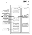
- FIG. 4 is a block diagram illustrating the robot system 1 according to the first embodiment. It is noted that FIG. 4 only illustrates those components necessary for description of the robot system 1, omitting those components of general nature.
- FIG. 4 will mainly focus on the internal configuration of the controller 50, and may occasionally simplify or omit the components that have been already described by referring to the drawings such as FIG. 1A .
- the controller 50 includes a control unit 51 and a storage 52.
- the control unit 51 further includes a conveyor controller 51a, a situation acquirer 51b, a missing workpiece determiner 51c (corresponding to the determiner), and an instructor 51d.
- the storage 52 is a storage device such as a hard disk drive and a non-volatile memory, and stores monitor area setting information 52a and combination information 52b.
- controller 50 not all the elements of the controller 50 illustrated in FIG. 4 need to be arranged within the single controller 50.
- at least one of the monitor area setting information 52a and the combination information 52b stored in the storage 52 is stored in an inner memory of the robot 30.
- at least one of the monitor area setting information 52a and the combination information 52b is stored in an upper-level device upper than the controller 50 and acquired as necessary from the upper-level device by the controller 50.
- control unit 51 is a Central Processing Unit (CPU) that is in charge of overall control of the controller 50.
- the conveyor controller 51a controls the first conveyor 10 and the second conveyor 20 to convey workpieces W and workpiece groups WG (occasionally, pallets P without workpieces W in the pallets P) to the monitor area GR of the robot 30.
- the first conveyor 10 and the second conveyor 20 will be collectively referred to as conveyors 10 and 20 in FIG. 4 .
- the situation acquirer 51b Based on the monitor area setting information 52a, the situation acquirer 51b sets an imaginary monitor area GR on the first conveyor 10 and the second conveyor 20. The situation acquirer 51b acquires a situation in the monitor area GR as the situation acquirer 51b finds it necessary considering the results of the detections performed by the detector 40.
- the monitor area setting information 52a is information required for setting the monitor area GR, and includes information such as the positions and dimensions of the movable range WR of the robot 30, the widths of the first conveyor 10 and the second conveyor 20, and the distance of the camera 41 from an imaging area.
- the situation acquirer 51b acquires situations of the workpieces W and the workpiece groups WG in the monitor area GR based on an image received from the camera 41, based on sensing data received from the photoelectric sensors 42, and based on rotation situations of the conveyors 10 and 20 received from the encoders 43.
- the situation acquirer 51b notifies the missing workpiece determiner 51c of the acquired situations.
- the missing workpiece determiner 51c determines whether any of the workpieces W on the first conveyor 10 in the monitor area GR are missing workpieces of any of the workpiece groups WG in the monitor area GR.
- the missing workpiece determiner 51c also refers to the combination information 52b.
- the combination information 52b includes combinations of a plurality of kinds of workpieces W that constitute the workpiece groups WG.
- the missing workpiece determiner 51c notifies the instructor 51d of the determination.
- the instructor 51d instructs the robot 30 to pick at least one of the workpieces W determined as missing workpieces, and to transfer the one workpiece W from the first conveyor 10 to the second conveyor 20.
- the instructor 51d instructs the robot 30 to hold and transfer the workpiece W by the method according to the first embodiment for picking a workpiece (see FIGs. 3B and 3C ).
- FIG. 5 is a flowchart of the procedure for the processing performed by the robot system 1 according to the first embodiment.
- the situation acquirer 51b acquires a situation in a predetermined monitor area GR on the first conveyor 10 and the second conveyor 20 (step S101). For example, the situation acquirer 51b acquires a situation in the monitor area GR prior to every operation of picking each workpiece W from the first conveyor 10.
- the missing workpiece determiner 51c determines whether any of the workpieces W in the monitor area GR on the first conveyor 10 are missing workpieces of any of the workpiece groups WG in the monitor area GR (step S102).
- the instructor 51d instructs the robot 30 to transfer at least one of the missing workpieces W from the first conveyor 10 to the second conveyor 20 (step S104).
- the instructor 51d instructs the robot 30 to transfer the workpieces W on the first conveyor 10 in the order that the workpieces W are conveyed on the first conveyor 10 (step S105).
- step S106 a determination is made as to whether the work is complete (step S106). When the work is complete ("Yes” at step S106), the processing ends. When the work is not complete ("No” at step S106), the controller 50 repeats the processing that starts from step S101.
- the robot system includes the first conveyor (corresponding to the first conveyor), the second conveyor (corresponding to the second conveyor), the robot, and the controller.
- the first conveyor conveys a plurality of kinds of workpieces.
- the second conveyor conveys workpiece groups each including a combination of the plurality of kinds of workpieces.
- the robot makes a predetermined movement.
- the controller controls the movement of the robot.
- the controller includes the situation acquirer, the missing workpiece determiner (corresponding to the determiner), and the instructor.
- the situation acquirer acquires a situation in the predetermined monitor area on the first conveyor and the second conveyor.
- the predetermined monitor area is set based on the movable range of the robot.
- the missing workpiece determiner determines whether any of the workpieces on the first conveyor in the monitor area are missing workpieces of any of the workpiece groups in the monitor area.
- the instructor instructs the robot to hold at least one of the workpieces determined as missing workpieces W by the determiner and to transfer the one workpiece from the first conveyor to the second conveyor.
- the robot system according to the first embodiment ensures more efficient transfer of the workpieces.
- any of the workpieces on the first conveyor in the monitor area are missing workpieces of at least one of the workpiece groups on the second conveyor, any of the missing workpieces are picked and transferred to the second conveyor.
- This configuration should not be construed in a limiting sense.
- Another possible embodiment is to prioritize a missing workpiece of a workpiece group in a most downstream area of the second conveyor. This configuration will be described below with reference to a second embodiment illustrated in FIGs. 6A to 6D .
- FIGs. 6A to 6D are respectively first to fourth diagrams illustrating a method according to the second embodiment for picking a workpiece.
- like reference numerals designate corresponding or identical elements throughout the first and second embodiments.
- the robot system according to the second embodiment is denoted with reference numeral "1'", not illustrated.
- the method according to the second embodiment for picking a workpiece is different from the first embodiment in that a missing workpiece W of a workpiece group WG in a most downstream area of the second conveyor 20 is prioritized.
- the method according to the second embodiment for picking a workpiece gives higher priority to workpieces W in a downstream area of the monitor area GR, and gives lower priority to workpieces W in an upstream area of the monitor area GR.
- a monitor area GR1 is set in the most downstream area of the second conveyor 20 in the monitor area GR. The monitor area GR1 is given highest priority.
- the determination is made separately for the monitor area GR1 and for the rest of the monitor area GR .
- the determination made for the monitor area GR1 is that a workpiece Wb, which is numbered "3" in the transfer order, a workpiece Wc, which is numbered “6” in the transfer order, and a workpiece Wd, which is numbered "7" in the transfer order, are missing workpieces in a pallet P1 in the monitor area GR1.
- the missing workpieces W are shaded by fine dots.
- the determination made for the rest of the monitor area GR is that workpieces Wa, which are "2", "4", and "5" in the transfer order, are missing workpieces in a pallet P2.
- the missing workpieces W are shaded by slanting lines.
- the workpiece Wb, the workpiece Wc, and the workpiece Wd which are respectively numbered “3", “6”, and “7” in the transfer order and which have been prioritized as missing workpieces W in the monitor area GR1, are respectively advanced to "2", "3", and "4" in the transfer order.
- the workpieces Wa which are numbered “2", “4", and “5" in the transfer order and which have been determined as missing workpieces W in the rest of the monitor area GR, are respectively increased to "5", "6", and "7” in the transfer order.
- the workpiece Wa circled by a dashed line in FIG. 6C has originally been transferrable with highest priority and is now lowered in priority. This configuration may not necessarily be applicable when the conveyance situation of the first conveyor 10 leads to such a determination that there is a possibility of the workpiece Wa lacking in combination on the second conveyer 20.
- the prioritized missing workpieces W are transferred to the second conveyor 20 in the transfer order thus changed (step S11).
- the method according to the second embodiment for picking a workpiece eliminates or minimizes lack of combination of the workpieces W, that is, ensures reliable transfer of the workpieces W. That is, the workpieces W are transferred more efficiently by the method according to the second embodiment.
- the method according to the second embodiment for picking a workpiece prioritizes a missing workpiece W of a workpiece group WG in the most downstream area of the second conveyor 20.
- the instructor 51d instructs the robot 30 to prioritize one workpiece W that is among the workpieces W determined as missing workpieces W by the missing workpiece determiner 51c and that is in the most downstream area of the second conveyor 20 in the monitor area GR.
- the robot 30 holds and transfers the prioritized one workpiece W. This configuration ensures more efficient transfer of the workpieces W.
- the first and second embodiments are implemented using the following robot apparatus.
- a robot apparatus 100 includes the robot 30 and the controller 50.
- the controller 50 controls the movement of the robot 30, and includes the situation acquirer 51b, the missing workpiece determiner 51c, and the instructor 51d.
- the situation acquirer 51b acquires a situation in a predetermined monitor area GR on the first and second conveyers 10 and 20.
- the predetermined monitor area GR is set based on the movable range of the robot 30.
- the missing workpiece determiner 51c determines whether any of the workpieces W on the first conveyor 10 in the monitor area GR are missing workpieces of any of the workpiece groups WG in the monitor area GR.
- the instructor 51d instructs the robot 30 to hold at least one of the workpieces W determined as the missing workpieces W by the missing workpiece determiner 51c, and to transfer the at least one workpiece W from the first conveyor 10 to the second conveyor 20.
- the transfer order in which the robot picks the workpieces is changed to eliminate or minimize lack of combination of the workpieces, in an attempt to transfer the workpieces more efficiently.
- This configuration should not be construed in a limiting sense.
- Another possible embodiment is to add control to change the conveyance speeds of the conveyors.
- the instructor 51d calculates appropriate control values for the conveyors 10 and 20 to eliminate or minimize lack of combination and missed picking, and instructs the conveyor controller 51a with the control values (see FIG. 4 ). It will be readily appreciated that the above-described embodiments are implementable without the control to change the conveyance speeds of the conveyors.
Landscapes
- Engineering & Computer Science (AREA)
- Mechanical Engineering (AREA)
- Robotics (AREA)
- General Engineering & Computer Science (AREA)
- Manufacturing & Machinery (AREA)
- Quality & Reliability (AREA)
- Physics & Mathematics (AREA)
- General Physics & Mathematics (AREA)
- Automation & Control Theory (AREA)
- Manipulator (AREA)
- Specific Conveyance Elements (AREA)
Priority Applications (1)
| Application Number | Priority Date | Filing Date | Title |
|---|---|---|---|
| SI201531618T SI2998077T1 (sl) | 2014-09-18 | 2015-09-04 | Robotski sistem, robotska naprava in postopek izbiranja obdelovanca |
Applications Claiming Priority (1)
| Application Number | Priority Date | Filing Date | Title |
|---|---|---|---|
| JP2014190444A JP6387760B2 (ja) | 2014-09-18 | 2014-09-18 | ロボットシステム、ロボット装置およびワークピッキング方法 |
Publications (3)
| Publication Number | Publication Date |
|---|---|
| EP2998077A2 true EP2998077A2 (de) | 2016-03-23 |
| EP2998077A3 EP2998077A3 (de) | 2016-07-27 |
| EP2998077B1 EP2998077B1 (de) | 2021-03-10 |
Family
ID=54140226
Family Applications (1)
| Application Number | Title | Priority Date | Filing Date |
|---|---|---|---|
| EP15183826.5A Active EP2998077B1 (de) | 2014-09-18 | 2015-09-04 | Robotersystem, robotervorrichtung und verfahren zum aufnehmen eines werkstücks |
Country Status (5)
| Country | Link |
|---|---|
| US (1) | US9346630B2 (de) |
| EP (1) | EP2998077B1 (de) |
| JP (1) | JP6387760B2 (de) |
| CN (1) | CN105437248B (de) |
| SI (1) | SI2998077T1 (de) |
Cited By (10)
| Publication number | Priority date | Publication date | Assignee | Title |
|---|---|---|---|---|
| WO2018125007A1 (en) * | 2017-01-02 | 2018-07-05 | Robotek Otomasyon Teknolojileri Sanayi Ticaret Limited Sirketi | The robotic production line and methods of flexible and chaotic production |
| CN109384039A (zh) * | 2017-08-03 | 2019-02-26 | 发那科株式会社 | 物品搬运装置 |
| US10346940B2 (en) | 2016-12-21 | 2019-07-09 | Fanuc Corporation | Robot system and production system |
| EP3534230A3 (de) * | 2018-03-02 | 2020-02-26 | Hitachi, Ltd. | Roboterarbeitssystem und verfahren zur steuerung des roboterarbeitssystems |
| DE102019125126B4 (de) * | 2018-09-27 | 2020-12-17 | Canon Kabushiki Kaisha | Informationsverarbeitungsvorrichtung, Informationsverarbeitungsverfahren und System |
| DE102018002423B4 (de) | 2017-03-31 | 2022-02-03 | Fanuc Corporation | Robotersteuerung, Vorrichtung für maschinelles Lernen und Verfahren für maschinelles Lernen |
| SE544741C2 (en) * | 2018-05-11 | 2022-11-01 | Genie Ind Bv | Waste Sorting Gantry Robot and associated method |
| US11679944B2 (en) | 2018-08-31 | 2023-06-20 | Fanuc Corporation | Article picking system |
| WO2025181661A1 (en) * | 2024-03-01 | 2025-09-04 | G.D S.P.A. | System and method for moving an article |
| DE102020005736B4 (de) | 2019-09-27 | 2026-01-22 | Fanuc Corporation | Maschinensystem zum Ausführen einer Werkstückauslassungserkennung |
Families Citing this family (14)
| Publication number | Priority date | Publication date | Assignee | Title |
|---|---|---|---|---|
| CN105775726B (zh) * | 2016-04-13 | 2017-12-22 | 英华达(南京)科技有限公司 | 拾取和放置装置及其应用方法 |
| JP6370842B2 (ja) | 2016-06-29 | 2018-08-08 | ファナック株式会社 | 仮置き部を備えた物品搬送装置 |
| JP6599827B2 (ja) * | 2016-08-29 | 2019-10-30 | ファナック株式会社 | ワーク取出システム |
| CN107097230A (zh) * | 2017-06-19 | 2017-08-29 | 苏州诚晟信息技术有限公司 | 一种节能环保型上料机器人 |
| CN107265114A (zh) * | 2017-06-19 | 2017-10-20 | 太仓弘杉环保科技有限公司 | 一种高效节能型上料机器人的工作方法 |
| JP6956348B2 (ja) * | 2018-03-02 | 2021-11-02 | 株式会社安川電機 | 食品箱詰めシステム、食品箱詰め装置及び食品箱詰め方法 |
| DE102018003269A1 (de) * | 2018-04-23 | 2019-10-24 | Franka Emika Gmbh | Verfahren zum Einfügen eines Gegenstands in eine Gegenstandsaufnahme mittels eines Robotermanipulators |
| DE102018003270A1 (de) * | 2018-04-23 | 2019-10-24 | Franka Emika Gmbh | Verfahren zum Einfügen von Gegenständen in eine gemeinsame Aufnahmevorrichtung |
| DE102018003271A1 (de) * | 2018-04-23 | 2019-10-24 | Franka Emika Gmbh | Verfahren zum Einfügen von Gegenständen in eine gemeinsame Gegenstandsaufnahme |
| US12486061B2 (en) | 2018-09-26 | 2025-12-02 | Dexterity, Inc. | Robotic kitting system |
| US11731792B2 (en) | 2018-09-26 | 2023-08-22 | Dexterity, Inc. | Kitting machine |
| DE102019118917B4 (de) * | 2019-07-12 | 2023-11-30 | Hans Weber Maschinenfabrik Gmbh | Verfahren zur Steuerung des Betriebs einer Umsetzeinrichtung, Umsetzeinrichtung zum automatisierbaren oder automatisierten Umsetzen eines Werkstücks und Fertigungseinrichtung, umfassend eine entsprechende Umsetzeinrichtung |
| US12059803B2 (en) | 2020-06-22 | 2024-08-13 | Material Handling Systems, Inc. | Conveyor system with multiple robot singulators and buffering conveyor |
| CN120735054B (zh) * | 2025-09-03 | 2025-12-02 | 中国科学院水生生物研究所 | 用于生物样本转移的机械臂控制方法及装置 |
Citations (1)
| Publication number | Priority date | Publication date | Assignee | Title |
|---|---|---|---|---|
| JP2002316716A (ja) | 2001-04-24 | 2002-10-31 | Shibuya Kogyo Co Ltd | 物品処理装置 |
Family Cites Families (13)
| Publication number | Priority date | Publication date | Assignee | Title |
|---|---|---|---|---|
| JPH0891579A (ja) * | 1994-09-27 | 1996-04-09 | Nippon Steel Corp | パレタイズシステム |
| FR2754239A1 (fr) * | 1996-10-08 | 1998-04-10 | Euresko | Dispositif alimentaire pour chaine de conditionnement d'assortiment d'articles et chaine mettant en oeuvre un tel dispositif |
| DE29701564U1 (de) * | 1997-01-30 | 1997-03-27 | Gerhard Schubert GmbH, 74564 Crailsheim | Pickerstraße mit entgegengesetztem Traytransport |
| DE10060348A1 (de) * | 2000-12-04 | 2002-06-06 | Peter Nagler | Verfahren zum automatisierten Sortieren von Objekten und Zusammenstellen von Sortimenten |
| JP3602817B2 (ja) * | 2001-10-24 | 2004-12-15 | ファナック株式会社 | 食品盛り付けロボット及び食品盛り付け装置 |
| JP2008296330A (ja) * | 2007-05-31 | 2008-12-11 | Fanuc Ltd | ロボットシミュレーション装置 |
| JP5198161B2 (ja) * | 2008-06-17 | 2013-05-15 | 東芝機械株式会社 | ハンドリング装置およびワークハンドリング方法 |
| DE102008046325A1 (de) * | 2008-08-29 | 2010-03-11 | SSI Schäfer PEEM GmbH | Verfahren und Vorrichtung zum mannlosen, vollautomatisierten Kommissionieren von Artikeln in Auftragsladehilfsmittel |
| JP5819618B2 (ja) * | 2011-03-08 | 2015-11-24 | 佐藤 一雄 | ワーク移載システム |
| JP5316580B2 (ja) * | 2011-05-17 | 2013-10-16 | 株式会社安川電機 | ロボットシステム |
| SG192295A1 (en) * | 2012-01-10 | 2013-08-30 | K One Ind Pte Ltd | Flexible assembly line for tray packaging |
| EP2876065A1 (de) * | 2012-07-20 | 2015-05-27 | Kabushiki Kaisha Yaskawa Denki | Robotersystem und artikelübertragungsverfahren |
| WO2014013609A1 (ja) * | 2012-07-20 | 2014-01-23 | 株式会社安川電機 | ロボットシステムおよび物品移送方法 |
-
2014
- 2014-09-18 JP JP2014190444A patent/JP6387760B2/ja active Active
-
2015
- 2015-09-04 SI SI201531618T patent/SI2998077T1/sl unknown
- 2015-09-04 EP EP15183826.5A patent/EP2998077B1/de active Active
- 2015-09-14 CN CN201510582760.2A patent/CN105437248B/zh active Active
- 2015-09-17 US US14/857,754 patent/US9346630B2/en active Active
Patent Citations (1)
| Publication number | Priority date | Publication date | Assignee | Title |
|---|---|---|---|---|
| JP2002316716A (ja) | 2001-04-24 | 2002-10-31 | Shibuya Kogyo Co Ltd | 物品処理装置 |
Cited By (15)
| Publication number | Priority date | Publication date | Assignee | Title |
|---|---|---|---|---|
| US10346940B2 (en) | 2016-12-21 | 2019-07-09 | Fanuc Corporation | Robot system and production system |
| DE102017222566B4 (de) * | 2016-12-21 | 2019-11-07 | Fanuc Corporation | Robotersystem und Produktionssystem |
| WO2018125007A1 (en) * | 2017-01-02 | 2018-07-05 | Robotek Otomasyon Teknolojileri Sanayi Ticaret Limited Sirketi | The robotic production line and methods of flexible and chaotic production |
| US11550303B2 (en) | 2017-01-02 | 2023-01-10 | Robotek Otomasyon Teknolojileri Sanayi Ticaret Limited Sirketi | Robotic production line and methods of flexible and chaotic production |
| DE102018002423B4 (de) | 2017-03-31 | 2022-02-03 | Fanuc Corporation | Robotersteuerung, Vorrichtung für maschinelles Lernen und Verfahren für maschinelles Lernen |
| DE102018212531B4 (de) * | 2017-08-03 | 2020-09-10 | Fanuc Corporation | Artikeltransfervorrichtung |
| US10596707B2 (en) | 2017-08-03 | 2020-03-24 | Fanuc Corporation | Article transfer device |
| CN109384039A (zh) * | 2017-08-03 | 2019-02-26 | 发那科株式会社 | 物品搬运装置 |
| EP3534230A3 (de) * | 2018-03-02 | 2020-02-26 | Hitachi, Ltd. | Roboterarbeitssystem und verfahren zur steuerung des roboterarbeitssystems |
| SE544741C2 (en) * | 2018-05-11 | 2022-11-01 | Genie Ind Bv | Waste Sorting Gantry Robot and associated method |
| US11679944B2 (en) | 2018-08-31 | 2023-06-20 | Fanuc Corporation | Article picking system |
| DE102019125126B4 (de) * | 2018-09-27 | 2020-12-17 | Canon Kabushiki Kaisha | Informationsverarbeitungsvorrichtung, Informationsverarbeitungsverfahren und System |
| US11541545B2 (en) | 2018-09-27 | 2023-01-03 | Canon Kabushiki Kaisha | Information processing apparatus, information processing method, and system |
| DE102020005736B4 (de) | 2019-09-27 | 2026-01-22 | Fanuc Corporation | Maschinensystem zum Ausführen einer Werkstückauslassungserkennung |
| WO2025181661A1 (en) * | 2024-03-01 | 2025-09-04 | G.D S.P.A. | System and method for moving an article |
Also Published As
| Publication number | Publication date |
|---|---|
| EP2998077B1 (de) | 2021-03-10 |
| JP2016060004A (ja) | 2016-04-25 |
| JP6387760B2 (ja) | 2018-09-12 |
| CN105437248B (zh) | 2017-11-28 |
| US20160083198A1 (en) | 2016-03-24 |
| US9346630B2 (en) | 2016-05-24 |
| EP2998077A3 (de) | 2016-07-27 |
| SI2998077T1 (sl) | 2021-08-31 |
| CN105437248A (zh) | 2016-03-30 |
Similar Documents
| Publication | Publication Date | Title |
|---|---|---|
| EP2998077B1 (de) | Robotersystem, robotervorrichtung und verfahren zum aufnehmen eines werkstücks | |
| US20160083199A1 (en) | Robot system and method for picking workpiece | |
| US8825212B2 (en) | Robot system | |
| US8880217B2 (en) | Picking system | |
| CN108372503B (zh) | 使用至少一个传感器的物品运送装置 | |
| CN104395211B (zh) | 机器人系统及物品移送方法 | |
| CN103659822B (zh) | 机器人设备 | |
| US20190047141A1 (en) | Robot system | |
| US20140079524A1 (en) | Robot system and workpiece transfer method | |
| CN104428224A (zh) | 机器人系统及物品移送方法 | |
| JP6011278B2 (ja) | 物品処理システム | |
| CN106540887A (zh) | 建筑垃圾智能机器人分拣系统及方法 | |
| JP2018034213A (ja) | ワーク取出システム | |
| JP2009297881A (ja) | ハンドリング装置、制御装置及び制御方法 | |
| CN105584823B (zh) | 输送系统及其输送方法 | |
| JP2017056528A (ja) | 移送システムおよび移送方法 | |
| JP6608894B2 (ja) | ロボットシステム | |
| CN105397813A (zh) | 机器人及其控制方法 | |
| CN105459115B (zh) | 一种工业机器人 | |
| JP2017109820A (ja) | 物品処理装置 | |
| JP5733522B2 (ja) | 物品処理装置 | |
| CN111573254A (zh) | 快递自动分拣机自动供包方法、装置和设备 |
Legal Events
| Date | Code | Title | Description |
|---|---|---|---|
| PUAI | Public reference made under article 153(3) epc to a published international application that has entered the european phase |
Free format text: ORIGINAL CODE: 0009012 |
|
| AK | Designated contracting states |
Kind code of ref document: A2 Designated state(s): AL AT BE BG CH CY CZ DE DK EE ES FI FR GB GR HR HU IE IS IT LI LT LU LV MC MK MT NL NO PL PT RO RS SE SI SK SM TR |
|
| AX | Request for extension of the european patent |
Extension state: BA ME |
|
| PUAL | Search report despatched |
Free format text: ORIGINAL CODE: 0009013 |
|
| AK | Designated contracting states |
Kind code of ref document: A3 Designated state(s): AL AT BE BG CH CY CZ DE DK EE ES FI FR GB GR HR HU IE IS IT LI LT LU LV MC MK MT NL NO PL PT RO RS SE SI SK SM TR |
|
| AX | Request for extension of the european patent |
Extension state: BA ME |
|
| RIC1 | Information provided on ipc code assigned before grant |
Ipc: G05B 19/418 20060101ALI20160620BHEP Ipc: B25J 9/16 20060101AFI20160620BHEP |
|
| STAA | Information on the status of an ep patent application or granted ep patent |
Free format text: STATUS: REQUEST FOR EXAMINATION WAS MADE |
|
| 17P | Request for examination filed |
Effective date: 20161123 |
|
| RBV | Designated contracting states (corrected) |
Designated state(s): AL AT BE BG CH CY CZ DE DK EE ES FI FR GB GR HR HU IE IS IT LI LT LU LV MC MK MT NL NO PL PT RO RS SE SI SK SM TR |
|
| STAA | Information on the status of an ep patent application or granted ep patent |
Free format text: STATUS: EXAMINATION IS IN PROGRESS |
|
| 17Q | First examination report despatched |
Effective date: 20171127 |
|
| GRAP | Despatch of communication of intention to grant a patent |
Free format text: ORIGINAL CODE: EPIDOSNIGR1 |
|
| STAA | Information on the status of an ep patent application or granted ep patent |
Free format text: STATUS: GRANT OF PATENT IS INTENDED |
|
| INTG | Intention to grant announced |
Effective date: 20201021 |
|
| GRAS | Grant fee paid |
Free format text: ORIGINAL CODE: EPIDOSNIGR3 |
|
| GRAA | (expected) grant |
Free format text: ORIGINAL CODE: 0009210 |
|
| STAA | Information on the status of an ep patent application or granted ep patent |
Free format text: STATUS: THE PATENT HAS BEEN GRANTED |
|
| AK | Designated contracting states |
Kind code of ref document: B1 Designated state(s): AL AT BE BG CH CY CZ DE DK EE ES FI FR GB GR HR HU IE IS IT LI LT LU LV MC MK MT NL NO PL PT RO RS SE SI SK SM TR |
|
| REG | Reference to a national code |
Ref country code: GB Ref legal event code: FG4D |
|
| REG | Reference to a national code |
Ref country code: AT Ref legal event code: REF Ref document number: 1369304 Country of ref document: AT Kind code of ref document: T Effective date: 20210315 Ref country code: CH Ref legal event code: EP |
|
| REG | Reference to a national code |
Ref country code: IE Ref legal event code: FG4D |
|
| REG | Reference to a national code |
Ref country code: DE Ref legal event code: R096 Ref document number: 602015066582 Country of ref document: DE |
|
| REG | Reference to a national code |
Ref country code: LT Ref legal event code: MG9D |
|
| PG25 | Lapsed in a contracting state [announced via postgrant information from national office to epo] |
Ref country code: LT Free format text: LAPSE BECAUSE OF FAILURE TO SUBMIT A TRANSLATION OF THE DESCRIPTION OR TO PAY THE FEE WITHIN THE PRESCRIBED TIME-LIMIT Effective date: 20210310 Ref country code: FI Free format text: LAPSE BECAUSE OF FAILURE TO SUBMIT A TRANSLATION OF THE DESCRIPTION OR TO PAY THE FEE WITHIN THE PRESCRIBED TIME-LIMIT Effective date: 20210310 Ref country code: GR Free format text: LAPSE BECAUSE OF FAILURE TO SUBMIT A TRANSLATION OF THE DESCRIPTION OR TO PAY THE FEE WITHIN THE PRESCRIBED TIME-LIMIT Effective date: 20210611 Ref country code: HR Free format text: LAPSE BECAUSE OF FAILURE TO SUBMIT A TRANSLATION OF THE DESCRIPTION OR TO PAY THE FEE WITHIN THE PRESCRIBED TIME-LIMIT Effective date: 20210310 Ref country code: BG Free format text: LAPSE BECAUSE OF FAILURE TO SUBMIT A TRANSLATION OF THE DESCRIPTION OR TO PAY THE FEE WITHIN THE PRESCRIBED TIME-LIMIT Effective date: 20210610 Ref country code: NO Free format text: LAPSE BECAUSE OF FAILURE TO SUBMIT A TRANSLATION OF THE DESCRIPTION OR TO PAY THE FEE WITHIN THE PRESCRIBED TIME-LIMIT Effective date: 20210610 |
|
| REG | Reference to a national code |
Ref country code: AT Ref legal event code: MK05 Ref document number: 1369304 Country of ref document: AT Kind code of ref document: T Effective date: 20210310 |
|
| REG | Reference to a national code |
Ref country code: NL Ref legal event code: MP Effective date: 20210310 |
|
| PG25 | Lapsed in a contracting state [announced via postgrant information from national office to epo] |
Ref country code: SE Free format text: LAPSE BECAUSE OF FAILURE TO SUBMIT A TRANSLATION OF THE DESCRIPTION OR TO PAY THE FEE WITHIN THE PRESCRIBED TIME-LIMIT Effective date: 20210310 Ref country code: RS Free format text: LAPSE BECAUSE OF FAILURE TO SUBMIT A TRANSLATION OF THE DESCRIPTION OR TO PAY THE FEE WITHIN THE PRESCRIBED TIME-LIMIT Effective date: 20210310 Ref country code: LV Free format text: LAPSE BECAUSE OF FAILURE TO SUBMIT A TRANSLATION OF THE DESCRIPTION OR TO PAY THE FEE WITHIN THE PRESCRIBED TIME-LIMIT Effective date: 20210310 |
|
| PG25 | Lapsed in a contracting state [announced via postgrant information from national office to epo] |
Ref country code: NL Free format text: LAPSE BECAUSE OF FAILURE TO SUBMIT A TRANSLATION OF THE DESCRIPTION OR TO PAY THE FEE WITHIN THE PRESCRIBED TIME-LIMIT Effective date: 20210310 |
|
| PG25 | Lapsed in a contracting state [announced via postgrant information from national office to epo] |
Ref country code: EE Free format text: LAPSE BECAUSE OF FAILURE TO SUBMIT A TRANSLATION OF THE DESCRIPTION OR TO PAY THE FEE WITHIN THE PRESCRIBED TIME-LIMIT Effective date: 20210310 Ref country code: CZ Free format text: LAPSE BECAUSE OF FAILURE TO SUBMIT A TRANSLATION OF THE DESCRIPTION OR TO PAY THE FEE WITHIN THE PRESCRIBED TIME-LIMIT Effective date: 20210310 Ref country code: AT Free format text: LAPSE BECAUSE OF FAILURE TO SUBMIT A TRANSLATION OF THE DESCRIPTION OR TO PAY THE FEE WITHIN THE PRESCRIBED TIME-LIMIT Effective date: 20210310 Ref country code: SM Free format text: LAPSE BECAUSE OF FAILURE TO SUBMIT A TRANSLATION OF THE DESCRIPTION OR TO PAY THE FEE WITHIN THE PRESCRIBED TIME-LIMIT Effective date: 20210310 |
|
| PG25 | Lapsed in a contracting state [announced via postgrant information from national office to epo] |
Ref country code: PT Free format text: LAPSE BECAUSE OF FAILURE TO SUBMIT A TRANSLATION OF THE DESCRIPTION OR TO PAY THE FEE WITHIN THE PRESCRIBED TIME-LIMIT Effective date: 20210712 Ref country code: PL Free format text: LAPSE BECAUSE OF FAILURE TO SUBMIT A TRANSLATION OF THE DESCRIPTION OR TO PAY THE FEE WITHIN THE PRESCRIBED TIME-LIMIT Effective date: 20210310 Ref country code: ES Free format text: LAPSE BECAUSE OF FAILURE TO SUBMIT A TRANSLATION OF THE DESCRIPTION OR TO PAY THE FEE WITHIN THE PRESCRIBED TIME-LIMIT Effective date: 20210310 Ref country code: SK Free format text: LAPSE BECAUSE OF FAILURE TO SUBMIT A TRANSLATION OF THE DESCRIPTION OR TO PAY THE FEE WITHIN THE PRESCRIBED TIME-LIMIT Effective date: 20210310 Ref country code: RO Free format text: LAPSE BECAUSE OF FAILURE TO SUBMIT A TRANSLATION OF THE DESCRIPTION OR TO PAY THE FEE WITHIN THE PRESCRIBED TIME-LIMIT Effective date: 20210310 Ref country code: IS Free format text: LAPSE BECAUSE OF FAILURE TO SUBMIT A TRANSLATION OF THE DESCRIPTION OR TO PAY THE FEE WITHIN THE PRESCRIBED TIME-LIMIT Effective date: 20210710 |
|
| REG | Reference to a national code |
Ref country code: DE Ref legal event code: R097 Ref document number: 602015066582 Country of ref document: DE |
|
| PLBE | No opposition filed within time limit |
Free format text: ORIGINAL CODE: 0009261 |
|
| STAA | Information on the status of an ep patent application or granted ep patent |
Free format text: STATUS: NO OPPOSITION FILED WITHIN TIME LIMIT |
|
| PG25 | Lapsed in a contracting state [announced via postgrant information from national office to epo] |
Ref country code: DK Free format text: LAPSE BECAUSE OF FAILURE TO SUBMIT A TRANSLATION OF THE DESCRIPTION OR TO PAY THE FEE WITHIN THE PRESCRIBED TIME-LIMIT Effective date: 20210310 Ref country code: AL Free format text: LAPSE BECAUSE OF FAILURE TO SUBMIT A TRANSLATION OF THE DESCRIPTION OR TO PAY THE FEE WITHIN THE PRESCRIBED TIME-LIMIT Effective date: 20210310 |
|
| 26N | No opposition filed |
Effective date: 20211213 |
|
| PG25 | Lapsed in a contracting state [announced via postgrant information from national office to epo] |
Ref country code: IT Free format text: LAPSE BECAUSE OF FAILURE TO SUBMIT A TRANSLATION OF THE DESCRIPTION OR TO PAY THE FEE WITHIN THE PRESCRIBED TIME-LIMIT Effective date: 20210310 |
|
| REG | Reference to a national code |
Ref country code: CH Ref legal event code: PL |
|
| REG | Reference to a national code |
Ref country code: BE Ref legal event code: MM Effective date: 20210930 |
|
| GBPC | Gb: european patent ceased through non-payment of renewal fee |
Effective date: 20210904 |
|
| PG25 | Lapsed in a contracting state [announced via postgrant information from national office to epo] |
Ref country code: IS Free format text: LAPSE BECAUSE OF FAILURE TO SUBMIT A TRANSLATION OF THE DESCRIPTION OR TO PAY THE FEE WITHIN THE PRESCRIBED TIME-LIMIT Effective date: 20210710 Ref country code: MC Free format text: LAPSE BECAUSE OF FAILURE TO SUBMIT A TRANSLATION OF THE DESCRIPTION OR TO PAY THE FEE WITHIN THE PRESCRIBED TIME-LIMIT Effective date: 20210310 |
|
| PG25 | Lapsed in a contracting state [announced via postgrant information from national office to epo] |
Ref country code: LU Free format text: LAPSE BECAUSE OF NON-PAYMENT OF DUE FEES Effective date: 20210904 Ref country code: IE Free format text: LAPSE BECAUSE OF NON-PAYMENT OF DUE FEES Effective date: 20210904 Ref country code: GB Free format text: LAPSE BECAUSE OF NON-PAYMENT OF DUE FEES Effective date: 20210904 Ref country code: FR Free format text: LAPSE BECAUSE OF NON-PAYMENT OF DUE FEES Effective date: 20210930 Ref country code: BE Free format text: LAPSE BECAUSE OF NON-PAYMENT OF DUE FEES Effective date: 20210930 |
|
| PG25 | Lapsed in a contracting state [announced via postgrant information from national office to epo] |
Ref country code: LI Free format text: LAPSE BECAUSE OF NON-PAYMENT OF DUE FEES Effective date: 20210930 Ref country code: CH Free format text: LAPSE BECAUSE OF NON-PAYMENT OF DUE FEES Effective date: 20210930 |
|
| PG25 | Lapsed in a contracting state [announced via postgrant information from national office to epo] |
Ref country code: HU Free format text: LAPSE BECAUSE OF FAILURE TO SUBMIT A TRANSLATION OF THE DESCRIPTION OR TO PAY THE FEE WITHIN THE PRESCRIBED TIME-LIMIT; INVALID AB INITIO Effective date: 20150904 |
|
| PG25 | Lapsed in a contracting state [announced via postgrant information from national office to epo] |
Ref country code: CY Free format text: LAPSE BECAUSE OF FAILURE TO SUBMIT A TRANSLATION OF THE DESCRIPTION OR TO PAY THE FEE WITHIN THE PRESCRIBED TIME-LIMIT Effective date: 20210310 |
|
| PG25 | Lapsed in a contracting state [announced via postgrant information from national office to epo] |
Ref country code: MK Free format text: LAPSE BECAUSE OF FAILURE TO SUBMIT A TRANSLATION OF THE DESCRIPTION OR TO PAY THE FEE WITHIN THE PRESCRIBED TIME-LIMIT Effective date: 20210310 |
|
| PG25 | Lapsed in a contracting state [announced via postgrant information from national office to epo] |
Ref country code: MT Free format text: LAPSE BECAUSE OF FAILURE TO SUBMIT A TRANSLATION OF THE DESCRIPTION OR TO PAY THE FEE WITHIN THE PRESCRIBED TIME-LIMIT Effective date: 20210310 |
|
| PGFP | Annual fee paid to national office [announced via postgrant information from national office to epo] |
Ref country code: DE Payment date: 20250730 Year of fee payment: 11 |
|
| PGFP | Annual fee paid to national office [announced via postgrant information from national office to epo] |
Ref country code: SI Payment date: 20250813 Year of fee payment: 11 |
|
| PG25 | Lapsed in a contracting state [announced via postgrant information from national office to epo] |
Ref country code: TR Free format text: LAPSE BECAUSE OF FAILURE TO SUBMIT A TRANSLATION OF THE DESCRIPTION OR TO PAY THE FEE WITHIN THE PRESCRIBED TIME-LIMIT Effective date: 20210310 |