EP2998094A2 - Buse a canal chaud - Google Patents
Buse a canal chaud Download PDFInfo
- Publication number
- EP2998094A2 EP2998094A2 EP15181436.5A EP15181436A EP2998094A2 EP 2998094 A2 EP2998094 A2 EP 2998094A2 EP 15181436 A EP15181436 A EP 15181436A EP 2998094 A2 EP2998094 A2 EP 2998094A2
- Authority
- EP
- European Patent Office
- Prior art keywords
- needle
- hot runner
- nozzle
- channel
- nozzle body
- Prior art date
- Legal status (The legal status is an assumption and is not a legal conclusion. Google has not performed a legal analysis and makes no representation as to the accuracy of the status listed.)
- Withdrawn
Links
- 239000000155 melt Substances 0.000 claims abstract description 80
- 239000000463 material Substances 0.000 claims abstract description 64
- 238000002347 injection Methods 0.000 claims abstract description 58
- 239000007924 injection Substances 0.000 claims abstract description 58
- 239000004033 plastic Substances 0.000 claims abstract description 57
- 229920003023 plastic Polymers 0.000 claims abstract description 57
- 238000001746 injection moulding Methods 0.000 claims abstract description 16
- 238000010137 moulding (plastic) Methods 0.000 claims abstract description 10
- 238000010438 heat treatment Methods 0.000 claims description 36
- 238000007789 sealing Methods 0.000 claims description 29
- 238000000465 moulding Methods 0.000 claims description 7
- 238000000926 separation method Methods 0.000 description 5
- 239000000126 substance Substances 0.000 description 4
- 230000015572 biosynthetic process Effects 0.000 description 3
- 238000012546 transfer Methods 0.000 description 3
- 210000001015 abdomen Anatomy 0.000 description 2
- 230000015556 catabolic process Effects 0.000 description 2
- 238000006731 degradation reaction Methods 0.000 description 2
- 238000004519 manufacturing process Methods 0.000 description 2
- 238000012545 processing Methods 0.000 description 2
- 238000006243 chemical reaction Methods 0.000 description 1
- 238000013461 design Methods 0.000 description 1
- 238000009792 diffusion process Methods 0.000 description 1
- 230000000694 effects Effects 0.000 description 1
- 239000012530 fluid Substances 0.000 description 1
- 239000004615 ingredient Substances 0.000 description 1
- 238000009434 installation Methods 0.000 description 1
- 238000002844 melting Methods 0.000 description 1
- 230000008018 melting Effects 0.000 description 1
- 239000002184 metal Substances 0.000 description 1
- 238000000034 method Methods 0.000 description 1
- 238000012986 modification Methods 0.000 description 1
- 230000004048 modification Effects 0.000 description 1
- 230000003287 optical effect Effects 0.000 description 1
- 230000035515 penetration Effects 0.000 description 1
- 239000005060 rubber Substances 0.000 description 1
- 239000007921 spray Substances 0.000 description 1
- 230000007704 transition Effects 0.000 description 1
- 230000003313 weakening effect Effects 0.000 description 1
Images


Classifications
-
- B—PERFORMING OPERATIONS; TRANSPORTING
- B29—WORKING OF PLASTICS; WORKING OF SUBSTANCES IN A PLASTIC STATE IN GENERAL
- B29C—SHAPING OR JOINING OF PLASTICS; SHAPING OF MATERIAL IN A PLASTIC STATE, NOT OTHERWISE PROVIDED FOR; AFTER-TREATMENT OF THE SHAPED PRODUCTS, e.g. REPAIRING
- B29C45/00—Injection moulding, i.e. forcing the required volume of moulding material through a nozzle into a closed mould; Apparatus therefor
- B29C45/17—Component parts, details or accessories; Auxiliary operations
- B29C45/26—Moulds
- B29C45/27—Sprue channels ; Runner channels or runner nozzles
- B29C45/28—Closure devices therefor
- B29C45/2806—Closure devices therefor consisting of needle valve systems
-
- B—PERFORMING OPERATIONS; TRANSPORTING
- B29—WORKING OF PLASTICS; WORKING OF SUBSTANCES IN A PLASTIC STATE IN GENERAL
- B29C—SHAPING OR JOINING OF PLASTICS; SHAPING OF MATERIAL IN A PLASTIC STATE, NOT OTHERWISE PROVIDED FOR; AFTER-TREATMENT OF THE SHAPED PRODUCTS, e.g. REPAIRING
- B29C45/00—Injection moulding, i.e. forcing the required volume of moulding material through a nozzle into a closed mould; Apparatus therefor
- B29C45/17—Component parts, details or accessories; Auxiliary operations
- B29C45/26—Moulds
- B29C45/27—Sprue channels ; Runner channels or runner nozzles
- B29C2045/2777—Means for controlling heat flow or temperature distribution in the nozzle
-
- B—PERFORMING OPERATIONS; TRANSPORTING
- B29—WORKING OF PLASTICS; WORKING OF SUBSTANCES IN A PLASTIC STATE IN GENERAL
- B29C—SHAPING OR JOINING OF PLASTICS; SHAPING OF MATERIAL IN A PLASTIC STATE, NOT OTHERWISE PROVIDED FOR; AFTER-TREATMENT OF THE SHAPED PRODUCTS, e.g. REPAIRING
- B29C45/00—Injection moulding, i.e. forcing the required volume of moulding material through a nozzle into a closed mould; Apparatus therefor
- B29C45/17—Component parts, details or accessories; Auxiliary operations
- B29C45/26—Moulds
- B29C45/27—Sprue channels ; Runner channels or runner nozzles
- B29C45/2737—Heating or cooling means therefor
Definitions
- the invention relates to a hot runner nozzle for injection molding of plastic moldings, wherein the hot runner nozzle is insertable into a mold of a H hinderkanalspritzgussvorraum, wherein the hot runner nozzle has a nozzle body, wherein in the nozzle body, a melt channel for plastic material is formed, wherein the melt channel up to a nozzle opening at an injection end of the Hot runner nozzle extends, the hot runner nozzle having a needle, wherein the needle is mounted longitudinally displaceable in the needle body in a nozzle guide body, wherein the nozzle opening through the needle in an open position of the needle can be opened and closed in a closed position of the needle, wherein in the open position, the plastic material can be passed into a mold cavity of the mold.
- Such hot runner nozzles are well known and are regularly used for injection molding of plastic moldings where a clean separation of plastic molding and an injection port of a mold cavity is desired.
- the needle forms together with an injection port a so-called needle valve, such that upon injection of a plastic material into a mold cavity, a gate diameter formed through the injection port can be closed by the needle.
- a spray residue of the plastic material is first pressed into the relevant plastic part.
- the needle is then arranged exactly flush with a surface of the plastic molded part, so that only a round mark is formed on the surface of the plastic molded part.
- thermal shutters a burr of excess plastic material regularly develops in the region of the injection opening due to stringing of the plastic material, which necessitates further processing of the relevant plastic parts.
- the melt channel with the plastic material is generally formed in a nozzle body of the hot runner nozzle in such a way that the needle runs completely or in large part through the melt passage.
- the plastic melt is thus located together with the needle, coaxially surrounding this, in a common bore in the nozzle body.
- the plastic material is usually supplied to the side of an upper end of the nozzle body this and then passed into the relevant hole or sections of the melt channel, in which the needle extends. When supplying the plastic material, this then flows around the needle, since it flows transversely to the needle in the common portion of the melt channel. Part of the plastic material recombines after separation by the needle behind the needle.
- a heating device and the melt channel can be arranged concentrically.
- the melt channel and the heating device are arranged next to one another so that the flat nozzles for injection molds can be used with mold cavities arranged particularly close to each other.
- a more or less pronounced lateral deflection of the hot runner nozzle can occur in the thermal expansion behavior of the hot runner nozzles due to the non-concentric but lateral arrangement of the heating device to the melt passage.
- an undesirable temperature increase in the region of the melt channel may occur, such that in a central region of the melt channel, a temperature profile increases sharply, which is undesirable in principle.
- the present invention is therefore based on the object to propose a hot runner nozzle for injection molding of plastic moldings, which has an improved sealing of a needle.
- the hot runner nozzle according to the invention for injection molding of plastic moldings can be used in a mold of a hot runner injection molding device, wherein the hot runner nozzle has a nozzle body, wherein in the nozzle body a melt channel for plastic material is formed, wherein the melt channel extends to a nozzle opening at an injection end of the hot runner nozzle, wherein the hot runner nozzle a needle, wherein the needle is longitudinally displaceably mounted in a needle guide channel in the nozzle body, the nozzle opening through the needle in an open position of the needle is openable and closed in a closed position of the needle, wherein in the open position, the plastic material passed into a mold cavity of the mold may be, wherein the melt channel extends to the injection end of the needle spaced in the nozzle body, such that the needle and the melt channel in the nozzle body side by side they are formed, wherein the nozzle body has at least one material recess, which is formed between the melt channel and the needle guide channel, and divides the nozzle body into
- the running in the nozzle body melt channel is thus formed separately from the nozzle body also extending in the needle guide channel, wherein the material recess adjacent the melt channel and the needle guide channel is formed so that these between the melt channel and the needle guide channel lies.
- the material recess thus divides the nozzle body into the spaced-apart housing regions, so that the melt channel is formed in a first housing region of the nozzle body and the needle guide channel is formed in a second housing region of the nozzle body. Due to the material recess, there is a thermal separation of the melt channel and the needle guide channel, which opens the possibility to temper the melt channel independently of the needle guide channel and vice versa.
- the needle guide channel may thus preferably have a lower temperature than the melt channel in which the molten plastic material flows.
- the needle guide channel or the second housing area with the needle guide channel can have a comparatively low temperature, a risk of diffusion of undesired substances via a seal or a sealing device on the needle guide channel is considerably reduced. A lifetime of the sealing device is substantially extended and the hot runner nozzle thereby longer usable.
- the hot runner nozzle may have a heating device.
- the heating device can be arranged in the nozzle body or on the nozzle body.
- the heating device may be a heating cartridge which is rod-shaped and is inserted in a nozzle bore parallel to the melt channel in the nozzle body.
- the heating device can be arranged on or in the nozzle body, wherein the heating device can be adapted to a position of the melt channel, such that based on a cross section of the nozzle body, a uniform temperature of the melt channel can be achieved.
- the melt channel can not be arranged coaxially to the heating device, which can be arranged regularly on an outer circumference of the nozzle body.
- the heater can at the melt on the channel farthest spaced side of the nozzle body to be designed relative to its cross section with a higher thermal output than on a side closest to the melt channel side of the nozzle body. Thus, an uneven heating of the melt channel can be avoided.
- the heating device and the melt channel can be arranged laterally next to one another in the nozzle body of the hot runner nozzle, wherein the heating device can be accommodated in a heating channel in the nozzle body, and wherein the nozzle body can have at least one further material recess, which can be formed between the melt channel and the heating channel , and can divide the nozzle body into spaced housing portions.
- a heat transfer from the heater to the melt channel can be influenced by the material of the nozzle body in such a way that is increased by the further material recess of the heat transfer resistance in the region of the further material recess.
- thermo profiles can be set in the longitudinal direction of the melt channel, which counteract excessive deformation of the hot runner nozzle by avoiding temperature peaks.
- temperature profiles can also be used to locally influence or adjust the viscosity of the plasticized plastic material in the melt channel. This can be counteracted, for example, by preventing heat sinks at problematic cross-sectional transitions in the region of the melt channel or adjacent areas of a blockage or an undesirable pressure build-up.
- the material recess may be formed as a longitudinal slot extending in the longitudinal direction of the nozzle body.
- the longitudinal slot may separate a heating region of the nozzle body receiving the heater between a nozzle body foot at the injection end for connection to an injection mold and a nozzle body head at a head end for receiving a nozzle tip.
- the material recess is formed as at least one transversely extending to the nozzle body longitudinal transverse slot, a heating element receiving the heating area of the nozzle body between a nozzle body for connection to an injection mold and a nozzle body head for receiving a nozzle tip in at least two axially from each other subdivided separate heating subregions.
- the melt channel can extend in the nozzle body at a distance from the needle until the end of injection, so that in the opening position of the needle a flow around the needle with plastic material can be avoided. This makes it possible that upon retraction of the needle from the nozzle opening in the open position of the Melting channel is substantially completely released, so that when a coincidence of plastic material and needle this is not flowed around with plastic material and form so-called fluid shadow. Further, a complete withdrawal of the needle from the hot runner nozzle or the nozzle body is not practical, since this would require a substantial modification of an actuator for opening and closing the hot runner nozzle or for moving the needle.
- a significantly increased needle stroke would therefore lead to an enlargement of a hot runner injection molding apparatus into which the hot runner nozzle is inserted, which would considerably increase the manufacturing costs of the hot runner injection molding apparatus.
- the hot runner nozzle it is therefore possible to avoid flow shadows without a significant increase in the needle stroke and possibly necessary conversions to a hot runner injection molding device.
- Under a stored in the hot runner nozzle needle is understood to mean a needle which extends at least a large part of a length of the hot runner nozzle through this or through the nozzle body.
- the needle is in direct contact with the nozzle body and is guided within it.
- Having the needle spaced from the melt channel means that plastic material in that particular region of the melt channel can not contact the needle so that the plastic material can flow around the needle.
- the plastic material can not completely surround the needle at any point relative to its cross-section.
- the needle guide channel may have a sealing device which seals the needle against the melt channel.
- the sealing device may also be designed as a bearing or a needle guide in the manner of a bore in the nozzle body or from a guide bush in the nozzle body.
- the sealing device may be formed by a fit between the needle and the needle guide channel. Since the needle and the needle guide channel relative to the melt channel have a relatively low temperature level, a particularly close fit can be selected, whereby a seal is much easier.
- the fit may be formed in sections or completely over the entire length of the needle guide channel. Such a fit is easy to manufacture and requires no further components for sealing.
- the sealing device may alternatively be formed by a sealing element.
- the sealing element may for example be a sealing bush made of metal, plastic or rubber.
- a sealing bush can also have the function of a guide element of the needle.
- the sealing bushing can prevent tilting of the needle in the nozzle body.
- the sealing element may also be a simple O-ring. In a further embodiment, it may be provided to form the sealing element in combination with a fit between the needle and the needle guide channel as a sealing device.
- the melt passage within the nozzle body may be formed of a supply passage portion and an injection passage portion, and then the injection passage portion may be formed at the injection end.
- the feed channel section may preferably run through the nozzle body beginning at the end of the hot runner nozzle opposite to the injection end or an end face of the nozzle body, as far as the injection channel section.
- the nozzle body can then be sealingly connected to its front side, regardless of the design of the mold, to a hot runner manifold, so that the plastic material can be introduced from the hot runner manifold directly into the Zunaturalkanalabites.
- the melt channel runs in sections spaced parallel from the needle in the Zu211kanalabites.
- the melt passage or the Zu2010kanalabites can be particularly easily formed by a parallel bore relative to a bore of the needle guide channel in the nozzle body.
- the holes in question may then be spaced so far apart that the needle does not come into contact with plastic material in the Zu2010kanalabites. This is particularly advantageous because then no longer a possible length expansion would have to be considered depending on a melt temperature of the plastic material.
- a flow around the needle with plastic material can be prevented in particular that in the closed position of the needle, the needle through the injection channel section extends to the nozzle opening and that in the open position, the needle releases the nozzle opening and pulled out of the injection channel section.
- the plastic material can then flow unhindered from the feed channel section into the injection channel section without the needle at least partially dividing the stream of plastic material.
- the feed channel section can be designed to be many times longer than the injection channel section.
- the needle guide channel can be designed to be many times longer than the injection channel section.
- a sealing device between the needle channel and needle at a great distance from the injection channel section to arrange so that in the region of the sealing device then a temperature level is particularly low, which may favor a formation of a sufficient sealing effect particularly.
- a possible maximum stroke of the needle may correspond to at least a length of the injection channel portion. This then ensures that the needle can be completely removed from the injection channel section. At the same time, it is possible to operate the hot runner nozzle with a smaller needle stroke and thus to produce plastic moldings which have flow shadows, if avoidance of floating shadow is not required.
- the nozzle body can form a round nozzle or a flat nozzle.
- a flat nozzle may then have a rectangular cross-section within which the needle extends.
- only one injection end is then formed on the nozzle body, d. H. the hot runner nozzle is formed only for injection molding a single mold cavity, wherein basically also a plurality of nozzle openings can be formed on a hot runner nozzle.
- the melt channel in the nozzle body in the middle, d. H. to be arranged between the needle guide channel and a heater, so that the needle guide channel is spaced as far as possible from the heater.
- the nozzle body may be integrally formed, whereby the hot runner nozzle is particularly compact formable, since no fastening means for the connection of individual parts of the nozzle body must be arranged in this.
- the hot runner nozzle may include a tip device that may be disposed on the nozzle body and that forms the nozzle orifice.
- the tip device can be arranged at the injection end of the nozzle body or the hot runner nozzle as an insert inserted into the hot runner nozzle or in the manner of a cap at the injection end, for example screwed or screwed on the nozzle body.
- the tip device can then also the hot runner nozzle or seal the nozzle body relative to a mold so that only in a region of the tip device plastic material can flow in a space between the hot runner nozzle and the mold.
- the hot runner injection molding device comprises a molding tool and at least one hot runner nozzle which can be inserted into the molding tool according to one of claims 1 to 18.
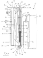
- the Fig. 1 and 2 show an embodiment of a hot runner nozzle 10, which is inserted into a mold 11 shown here only hinted.
- the molding tool 11 includes, inter alia, a mold plate 12, in which a mold cavity 13 shown here in sections is formed.
- the hot runner nozzle 10 has a substantially rectangular nozzle body 14, at the injection end 15 of which a tip device 16 is arranged.
- the tip device 16 comprises a bushing 17 which is inserted into the nozzle body 14, and a guide ring 18 which centers the hot runner nozzle 10 in a mounting opening 19 of the molding tool 11.
- Transverse ends 20 of the nozzle body 14 are semicircular.
- a mounting plate 22 is attached.
- the mounting plate 22 covers a heating channel 23, in a heating cartridge 24 is used with connecting lines 25. Adjacent to the heating channel 23, a melt channel 26 is formed in the one-piece nozzle body 14. The melt channel 26 extends from an end face 27 at the head end 21 of the nozzle body 14 to a nozzle opening 28 at the injection end 15. Parallel to a longitudinal axis 29 of the hot runner nozzle 10, a needle 30 is mounted longitudinally displaceable in the nozzle body 14 in a needle guide channel 31. The needle 30 is used to open and close the nozzle opening 28 and can be moved from an open position 32 shown here into a closed position, not shown, for closing the nozzle opening 28.
- Plastic material which is not shown here flows in the opening position 32 of the needle 30 through the melt channel 26 into the mold cavity 13, wherein the plasticized plastic material then also into a gap 33 formed between the nozzle body 14 and the mounting opening 19 in front of an injection opening 34 of the mold cavity thirteenth , entry.
- the gap 33 is sealed in particular by the guide ring 18.
- the melt channel 26 is formed from a feed channel section 35 and from an injection channel section 36.
- the feed channel section 35 is formed in the nozzle body 14 so that the plastic material in the feed channel section 35 can not contact the needle 30.
- a bore 37 of the Zutechnologykanalabitess 35 from a bore 38 of the needle guide channel 31 and thus spaced from the needle 30.
- the injection channel section 36 extends coaxially relative to the needle 30 here.
- the needle 30 When injecting plastic material into the mold cavity 13, the needle 30 is displaced by a stroke H from the injection channel section 36, as in FIG Fig. 1 shown pulled out, such that the plastic material can flow freely through the injection channel section 36 and the needle 30 is not flowed around by the plastic material.
- a sealing bush 39 is inserted, which forms a sealing device 40 in the needle guide channel 31.
- a sealing device 40 in the bore 38 of the needle guide channel 31.
- the nozzle body 14 is formed by a material recess 41, which is formed by a longitudinal slot 42, in a housing region 43 with the needle guide channel 31 and in a housing region 44 with the melt channel 26 or the feed channel section 35.
- the longitudinal slot 42 extends into the vicinity of the injection channel section 36, so that the housing regions 43 and 44 are connected to one another at the injection end 15.
- a further material recess 45 divides the nozzle body 14 into a housing region 46 with the heating channel 23 and into the housing region 44.
- the material recess 45 forms a longitudinal slot 47 extending between the housing regions 44 and 46.
- the housing portions 44 and 46 are connected to each other at the head end 21 and the injection end 15 of the nozzle body 14.
- a transverse slot 48 divides the housing region 46 into an upper heating channel section 49 and a lower heating channel section 50. Because the heating cartridge 24 is spaced comparatively far from the needle 30 and the longitudinal slot 42 separates the needle guide channel 31 from the melt channel 26, there is heat transfer into the Housing portion 43 and the needle guide channel 31 only on the housing portions 43 and 44 connecting the injection end 15 possible.
- a temperature level in the housing portion 43 is substantially lower than in the housing portion 46. The formation of a secure seal of the needle 30 relative to the needle guide channel 31 is thus substantially facilitated.
- the Fig. 3 shows a further embodiment of a hot runner nozzle 51 in a longitudinal sectional view, wherein, in contrast to the hot runner nozzle of the Fig. 1 and 2
- a needle guide channel 52 is formed with a bore 53 and a bore 54.
- the bore 54 forms together with a needle 55 a clearance 56 from.
- the clearance fit 56 is a sealing device 57, which prevents penetration of plastic material into the bores 53 and 54.
Landscapes
- Engineering & Computer Science (AREA)
- Manufacturing & Machinery (AREA)
- Mechanical Engineering (AREA)
- Moulds For Moulding Plastics Or The Like (AREA)
Applications Claiming Priority (1)
| Application Number | Priority Date | Filing Date | Title |
|---|---|---|---|
| DE102014012541 | 2014-08-28 |
Publications (2)
| Publication Number | Publication Date |
|---|---|
| EP2998094A2 true EP2998094A2 (fr) | 2016-03-23 |
| EP2998094A3 EP2998094A3 (fr) | 2016-05-25 |
Family
ID=54065177
Family Applications (1)
| Application Number | Title | Priority Date | Filing Date |
|---|---|---|---|
| EP15181436.5A Withdrawn EP2998094A3 (fr) | 2014-08-28 | 2015-08-18 | Buse a canal chaud |
Country Status (1)
| Country | Link |
|---|---|
| EP (1) | EP2998094A3 (fr) |
Cited By (1)
| Publication number | Priority date | Publication date | Assignee | Title |
|---|---|---|---|---|
| EP4450250A1 (fr) * | 2023-04-19 | 2024-10-23 | Inglass S.p.A. | Corps d'injecteur pour moulage par injection et ensemble de montage associé |
Family Cites Families (7)
| Publication number | Priority date | Publication date | Assignee | Title |
|---|---|---|---|---|
| NL9201886A (nl) * | 1992-10-29 | 1994-05-16 | Eurotool Bv | Mondstuksamenstel met daardoorheen lopend regelorgaan voor een spuitgietinrichting, alsmede een mondstuk en een inzetstuk daarvoor, evenals een werkwijze voor het instellen van de speling rond dat regelorgaan. |
| US5288225A (en) * | 1992-12-14 | 1994-02-22 | Husky Injection Molding Systems Ltd. | Pressure balanced valve stem |
| US7207796B2 (en) * | 2004-07-01 | 2007-04-24 | Husky Injection Moldiing Systems Ltd. | Hot runner coinjection nozzle with thermally separated melt channels |
| DE202006012676U1 (de) * | 2006-03-29 | 2007-08-09 | EWIKON Heißkanalsysteme GmbH & Co. KG | Nadelverschlussdüse |
| DE102007050332B4 (de) * | 2007-10-18 | 2010-12-02 | Kraussmaffei Technologies Gmbh | Formwerkzeug mit integriertem Injektor |
| DE102007063300B4 (de) * | 2007-12-27 | 2016-04-14 | Heitec-Heisskanaltechnik Gmbh | Heißkanaldüse für eine Spritzgießvorrichtung |
| CH706910A2 (de) * | 2012-09-04 | 2014-03-14 | Schoettli Ag | Heisskanaldüse zum Einspritzen von thermoplastischem Kunststoff in ein Formwerkzeug. |
-
2015
- 2015-08-18 EP EP15181436.5A patent/EP2998094A3/fr not_active Withdrawn
Non-Patent Citations (1)
| Title |
|---|
| None |
Cited By (2)
| Publication number | Priority date | Publication date | Assignee | Title |
|---|---|---|---|---|
| EP4450250A1 (fr) * | 2023-04-19 | 2024-10-23 | Inglass S.p.A. | Corps d'injecteur pour moulage par injection et ensemble de montage associé |
| US12570030B2 (en) | 2023-04-19 | 2026-03-10 | Inglass S.P.A. | Injector body for injection molding |
Also Published As
| Publication number | Publication date |
|---|---|
| EP2998094A3 (fr) | 2016-05-25 |
Similar Documents
| Publication | Publication Date | Title |
|---|---|---|
| AT516225B1 (de) | Verfahren und Spritzgussdüse zum Herstellen von Spritzgussteilen aus Kunststoff | |
| EP0962296A2 (fr) | Buse à fermeture à aiguille | |
| EP2004382B1 (fr) | Outil de moulage par injection à canaux chauds avec buse de fermeture à aiguille | |
| DE102007052597A1 (de) | Angußadapter sowie Angußsystem für einen Angußadapter | |
| EP2633971B1 (fr) | Buse de moulage par injection avec des aiguilles d'obturation guidées par manchon de guidage et dispositif de moulage ainsi équipé | |
| EP1603729B1 (fr) | Buse de vanne pointeau | |
| EP3609672B1 (fr) | Connecteur enfichable en matière plastique et procédé de fabrication associé | |
| EP2998094A2 (fr) | Buse a canal chaud | |
| WO2004071742A1 (fr) | Procede de production d'articles moules par injection et buse a obturation a aiguille pour moule a injection | |
| EP3524402B1 (fr) | Buse de fermeture à aiguille actionnée pourvue de canal d'aiguille séparé et de canal de fusion | |
| EP3184279B1 (fr) | Buse de moulage par injection comprenant un insert | |
| DE102009060797B4 (de) | Düse für eine Spritzgießmaschine, Spritzgießmaschine mit einer derartigen Düse und Verfahren zur Regelung der Düse | |
| EP2243613A1 (fr) | Dispositif de buses et procédé d'injection de pièces de formage en matière synthétique | |
| DE102015000128B4 (de) | Vorrichtung zum Spritzgießen von Formteilen mit einem Schneckenkolben und einer Rückstromsperre auf Spritzgießmaschinen | |
| DE102006035816B4 (de) | Drossel für Spritzgießmaschine zum Spritzgießen von Kautschuk- bzw. Elastomermaterialien | |
| AT520389B1 (de) | Verfahren zum Herstellen von Spritzgussteilen aus Kunststoff | |
| EP2952326A1 (fr) | Système de buse d'obturateur à aiguille | |
| EP3822059B1 (fr) | Système d'injection de matière plastique dans un moule d'injection allongé d'une machine d'injection de matière plastique | |
| DE112014005406T5 (de) | Heißkanalspritzgießvorrichtung und Verfahren zum seitlichen Anspritzen mit unabhängigen Ventilnadeln | |
| AT519152A1 (de) | Einspritzeinheit | |
| EP2952324A1 (fr) | Moule à injection pour produit à injecter | |
| DE10301241B3 (de) | Kaltkanal-Einspritzdüse | |
| AT503970A2 (de) | Verfahren zum spritzgiessen eines formteils aus kunststoff und spritzgiessvorrichtung | |
| DE102004042615A1 (de) | Rückströmsperre für Spritzgießmaschinen | |
| DE202008002757U1 (de) | Nadelverschlussdüse zum Einbringen von flüssigem Kunststoff in eine Spritzgussform |
Legal Events
| Date | Code | Title | Description |
|---|---|---|---|
| PUAI | Public reference made under article 153(3) epc to a published international application that has entered the european phase |
Free format text: ORIGINAL CODE: 0009012 |
|
| AK | Designated contracting states |
Kind code of ref document: A2 Designated state(s): AL AT BE BG CH CY CZ DE DK EE ES FI FR GB GR HR HU IE IS IT LI LT LU LV MC MK MT NL NO PL PT RO RS SE SI SK SM TR |
|
| AX | Request for extension of the european patent |
Extension state: BA ME |
|
| PUAL | Search report despatched |
Free format text: ORIGINAL CODE: 0009013 |
|
| AK | Designated contracting states |
Kind code of ref document: A3 Designated state(s): AL AT BE BG CH CY CZ DE DK EE ES FI FR GB GR HR HU IE IS IT LI LT LU LV MC MK MT NL NO PL PT RO RS SE SI SK SM TR |
|
| AX | Request for extension of the european patent |
Extension state: BA ME |
|
| RIC1 | Information provided on ipc code assigned before grant |
Ipc: B29C 45/28 20060101ALI20160419BHEP Ipc: B29C 45/27 20060101AFI20160419BHEP |
|
| STAA | Information on the status of an ep patent application or granted ep patent |
Free format text: STATUS: THE APPLICATION HAS BEEN PUBLISHED |
|
| STAA | Information on the status of an ep patent application or granted ep patent |
Free format text: STATUS: THE APPLICATION IS DEEMED TO BE WITHDRAWN |
|
| 18D | Application deemed to be withdrawn |
Effective date: 20161126 |