EP2998112A1 - Film de protection, élément réfléchissant et procédé de fabrication du film de protection - Google Patents
Film de protection, élément réfléchissant et procédé de fabrication du film de protection Download PDFInfo
- Publication number
- EP2998112A1 EP2998112A1 EP14797913.2A EP14797913A EP2998112A1 EP 2998112 A1 EP2998112 A1 EP 2998112A1 EP 14797913 A EP14797913 A EP 14797913A EP 2998112 A1 EP2998112 A1 EP 2998112A1
- Authority
- EP
- European Patent Office
- Prior art keywords
- film
- layer
- glass
- low
- sample
- Prior art date
- Legal status (The legal status is an assumption and is not a legal conclusion. Google has not performed a legal analysis and makes no representation as to the accuracy of the status listed.)
- Granted
Links
Images

Classifications
-
- G—PHYSICS
- G02—OPTICS
- G02B—OPTICAL ELEMENTS, SYSTEMS OR APPARATUS
- G02B19/00—Condensers, e.g. light collectors or similar non-imaging optics
- G02B19/0033—Condensers, e.g. light collectors or similar non-imaging optics characterised by the use
- G02B19/0038—Condensers, e.g. light collectors or similar non-imaging optics characterised by the use for use with ambient light
- G02B19/0042—Condensers, e.g. light collectors or similar non-imaging optics characterised by the use for use with ambient light for use with direct solar radiation
-
- C—CHEMISTRY; METALLURGY
- C03—GLASS; MINERAL OR SLAG WOOL
- C03C—CHEMICAL COMPOSITION OF GLASSES, GLAZES OR VITREOUS ENAMELS; SURFACE TREATMENT OF GLASS; SURFACE TREATMENT OF FIBRES OR FILAMENTS MADE FROM GLASS, MINERALS OR SLAGS; JOINING GLASS TO GLASS OR OTHER MATERIALS
- C03C17/00—Surface treatment of glass, not in the form of fibres or filaments, by coating
- C03C17/34—Surface treatment of glass, not in the form of fibres or filaments, by coating with at least two coatings having different compositions
- C03C17/36—Surface treatment of glass, not in the form of fibres or filaments, by coating with at least two coatings having different compositions at least one coating being a metal
- C03C17/3602—Surface treatment of glass, not in the form of fibres or filaments, by coating with at least two coatings having different compositions at least one coating being a metal the metal being present as a layer
- C03C17/3618—Coatings of type glass/inorganic compound/other inorganic layers, at least one layer being metallic
-
- C—CHEMISTRY; METALLURGY
- C03—GLASS; MINERAL OR SLAG WOOL
- C03C—CHEMICAL COMPOSITION OF GLASSES, GLAZES OR VITREOUS ENAMELS; SURFACE TREATMENT OF GLASS; SURFACE TREATMENT OF FIBRES OR FILAMENTS MADE FROM GLASS, MINERALS OR SLAGS; JOINING GLASS TO GLASS OR OTHER MATERIALS
- C03C17/00—Surface treatment of glass, not in the form of fibres or filaments, by coating
- C03C17/34—Surface treatment of glass, not in the form of fibres or filaments, by coating with at least two coatings having different compositions
- C03C17/36—Surface treatment of glass, not in the form of fibres or filaments, by coating with at least two coatings having different compositions at least one coating being a metal
- C03C17/3602—Surface treatment of glass, not in the form of fibres or filaments, by coating with at least two coatings having different compositions at least one coating being a metal the metal being present as a layer
- C03C17/3626—Surface treatment of glass, not in the form of fibres or filaments, by coating with at least two coatings having different compositions at least one coating being a metal the metal being present as a layer one layer at least containing a nitride, oxynitride, boronitride or carbonitride
-
- C—CHEMISTRY; METALLURGY
- C03—GLASS; MINERAL OR SLAG WOOL
- C03C—CHEMICAL COMPOSITION OF GLASSES, GLAZES OR VITREOUS ENAMELS; SURFACE TREATMENT OF GLASS; SURFACE TREATMENT OF FIBRES OR FILAMENTS MADE FROM GLASS, MINERALS OR SLAGS; JOINING GLASS TO GLASS OR OTHER MATERIALS
- C03C17/00—Surface treatment of glass, not in the form of fibres or filaments, by coating
- C03C17/34—Surface treatment of glass, not in the form of fibres or filaments, by coating with at least two coatings having different compositions
- C03C17/36—Surface treatment of glass, not in the form of fibres or filaments, by coating with at least two coatings having different compositions at least one coating being a metal
- C03C17/3602—Surface treatment of glass, not in the form of fibres or filaments, by coating with at least two coatings having different compositions at least one coating being a metal the metal being present as a layer
- C03C17/3639—Multilayers containing at least two functional metal layers
-
- C—CHEMISTRY; METALLURGY
- C03—GLASS; MINERAL OR SLAG WOOL
- C03C—CHEMICAL COMPOSITION OF GLASSES, GLAZES OR VITREOUS ENAMELS; SURFACE TREATMENT OF GLASS; SURFACE TREATMENT OF FIBRES OR FILAMENTS MADE FROM GLASS, MINERALS OR SLAGS; JOINING GLASS TO GLASS OR OTHER MATERIALS
- C03C17/00—Surface treatment of glass, not in the form of fibres or filaments, by coating
- C03C17/34—Surface treatment of glass, not in the form of fibres or filaments, by coating with at least two coatings having different compositions
- C03C17/36—Surface treatment of glass, not in the form of fibres or filaments, by coating with at least two coatings having different compositions at least one coating being a metal
- C03C17/3602—Surface treatment of glass, not in the form of fibres or filaments, by coating with at least two coatings having different compositions at least one coating being a metal the metal being present as a layer
- C03C17/3644—Surface treatment of glass, not in the form of fibres or filaments, by coating with at least two coatings having different compositions at least one coating being a metal the metal being present as a layer the metal being silver
-
- C—CHEMISTRY; METALLURGY
- C03—GLASS; MINERAL OR SLAG WOOL
- C03C—CHEMICAL COMPOSITION OF GLASSES, GLAZES OR VITREOUS ENAMELS; SURFACE TREATMENT OF GLASS; SURFACE TREATMENT OF FIBRES OR FILAMENTS MADE FROM GLASS, MINERALS OR SLAGS; JOINING GLASS TO GLASS OR OTHER MATERIALS
- C03C17/00—Surface treatment of glass, not in the form of fibres or filaments, by coating
- C03C17/34—Surface treatment of glass, not in the form of fibres or filaments, by coating with at least two coatings having different compositions
- C03C17/36—Surface treatment of glass, not in the form of fibres or filaments, by coating with at least two coatings having different compositions at least one coating being a metal
- C03C17/3602—Surface treatment of glass, not in the form of fibres or filaments, by coating with at least two coatings having different compositions at least one coating being a metal the metal being present as a layer
- C03C17/3647—Surface treatment of glass, not in the form of fibres or filaments, by coating with at least two coatings having different compositions at least one coating being a metal the metal being present as a layer in combination with other metals, silver being more than 50%
-
- C—CHEMISTRY; METALLURGY
- C03—GLASS; MINERAL OR SLAG WOOL
- C03C—CHEMICAL COMPOSITION OF GLASSES, GLAZES OR VITREOUS ENAMELS; SURFACE TREATMENT OF GLASS; SURFACE TREATMENT OF FIBRES OR FILAMENTS MADE FROM GLASS, MINERALS OR SLAGS; JOINING GLASS TO GLASS OR OTHER MATERIALS
- C03C17/00—Surface treatment of glass, not in the form of fibres or filaments, by coating
- C03C17/34—Surface treatment of glass, not in the form of fibres or filaments, by coating with at least two coatings having different compositions
- C03C17/36—Surface treatment of glass, not in the form of fibres or filaments, by coating with at least two coatings having different compositions at least one coating being a metal
- C03C17/3602—Surface treatment of glass, not in the form of fibres or filaments, by coating with at least two coatings having different compositions at least one coating being a metal the metal being present as a layer
- C03C17/3652—Surface treatment of glass, not in the form of fibres or filaments, by coating with at least two coatings having different compositions at least one coating being a metal the metal being present as a layer the coating stack containing at least one sacrificial layer to protect the metal from oxidation
-
- C—CHEMISTRY; METALLURGY
- C03—GLASS; MINERAL OR SLAG WOOL
- C03C—CHEMICAL COMPOSITION OF GLASSES, GLAZES OR VITREOUS ENAMELS; SURFACE TREATMENT OF GLASS; SURFACE TREATMENT OF FIBRES OR FILAMENTS MADE FROM GLASS, MINERALS OR SLAGS; JOINING GLASS TO GLASS OR OTHER MATERIALS
- C03C17/00—Surface treatment of glass, not in the form of fibres or filaments, by coating
- C03C17/34—Surface treatment of glass, not in the form of fibres or filaments, by coating with at least two coatings having different compositions
- C03C17/36—Surface treatment of glass, not in the form of fibres or filaments, by coating with at least two coatings having different compositions at least one coating being a metal
- C03C17/3602—Surface treatment of glass, not in the form of fibres or filaments, by coating with at least two coatings having different compositions at least one coating being a metal the metal being present as a layer
- C03C17/3657—Surface treatment of glass, not in the form of fibres or filaments, by coating with at least two coatings having different compositions at least one coating being a metal the metal being present as a layer the multilayer coating having optical properties
- C03C17/366—Low-emissivity or solar control coatings
-
- C—CHEMISTRY; METALLURGY
- C03—GLASS; MINERAL OR SLAG WOOL
- C03C—CHEMICAL COMPOSITION OF GLASSES, GLAZES OR VITREOUS ENAMELS; SURFACE TREATMENT OF GLASS; SURFACE TREATMENT OF FIBRES OR FILAMENTS MADE FROM GLASS, MINERALS OR SLAGS; JOINING GLASS TO GLASS OR OTHER MATERIALS
- C03C17/00—Surface treatment of glass, not in the form of fibres or filaments, by coating
- C03C17/34—Surface treatment of glass, not in the form of fibres or filaments, by coating with at least two coatings having different compositions
- C03C17/36—Surface treatment of glass, not in the form of fibres or filaments, by coating with at least two coatings having different compositions at least one coating being a metal
- C03C17/3602—Surface treatment of glass, not in the form of fibres or filaments, by coating with at least two coatings having different compositions at least one coating being a metal the metal being present as a layer
- C03C17/3657—Surface treatment of glass, not in the form of fibres or filaments, by coating with at least two coatings having different compositions at least one coating being a metal the metal being present as a layer the multilayer coating having optical properties
- C03C17/3663—Surface treatment of glass, not in the form of fibres or filaments, by coating with at least two coatings having different compositions at least one coating being a metal the metal being present as a layer the multilayer coating having optical properties specially adapted for use as mirrors
-
- C—CHEMISTRY; METALLURGY
- C23—COATING METALLIC MATERIAL; COATING MATERIAL WITH METALLIC MATERIAL; CHEMICAL SURFACE TREATMENT; DIFFUSION TREATMENT OF METALLIC MATERIAL; COATING BY VACUUM EVAPORATION, BY SPUTTERING, BY ION IMPLANTATION OR BY CHEMICAL VAPOUR DEPOSITION, IN GENERAL; INHIBITING CORROSION OF METALLIC MATERIAL OR INCRUSTATION IN GENERAL
- C23C—COATING METALLIC MATERIAL; COATING MATERIAL WITH METALLIC MATERIAL; SURFACE TREATMENT OF METALLIC MATERIAL BY DIFFUSION INTO THE SURFACE, BY CHEMICAL CONVERSION OR SUBSTITUTION; COATING BY VACUUM EVAPORATION, BY SPUTTERING, BY ION IMPLANTATION OR BY CHEMICAL VAPOUR DEPOSITION, IN GENERAL
- C23C14/00—Coating by vacuum evaporation, by sputtering or by ion implantation of the coating forming material
- C23C14/06—Coating by vacuum evaporation, by sputtering or by ion implantation of the coating forming material characterised by the coating material
- C23C14/0641—Nitrides
-
- C—CHEMISTRY; METALLURGY
- C23—COATING METALLIC MATERIAL; COATING MATERIAL WITH METALLIC MATERIAL; CHEMICAL SURFACE TREATMENT; DIFFUSION TREATMENT OF METALLIC MATERIAL; COATING BY VACUUM EVAPORATION, BY SPUTTERING, BY ION IMPLANTATION OR BY CHEMICAL VAPOUR DEPOSITION, IN GENERAL; INHIBITING CORROSION OF METALLIC MATERIAL OR INCRUSTATION IN GENERAL
- C23C—COATING METALLIC MATERIAL; COATING MATERIAL WITH METALLIC MATERIAL; SURFACE TREATMENT OF METALLIC MATERIAL BY DIFFUSION INTO THE SURFACE, BY CHEMICAL CONVERSION OR SUBSTITUTION; COATING BY VACUUM EVAPORATION, BY SPUTTERING, BY ION IMPLANTATION OR BY CHEMICAL VAPOUR DEPOSITION, IN GENERAL
- C23C14/00—Coating by vacuum evaporation, by sputtering or by ion implantation of the coating forming material
- C23C14/06—Coating by vacuum evaporation, by sputtering or by ion implantation of the coating forming material characterised by the coating material
- C23C14/10—Glass or silica
-
- C—CHEMISTRY; METALLURGY
- C23—COATING METALLIC MATERIAL; COATING MATERIAL WITH METALLIC MATERIAL; CHEMICAL SURFACE TREATMENT; DIFFUSION TREATMENT OF METALLIC MATERIAL; COATING BY VACUUM EVAPORATION, BY SPUTTERING, BY ION IMPLANTATION OR BY CHEMICAL VAPOUR DEPOSITION, IN GENERAL; INHIBITING CORROSION OF METALLIC MATERIAL OR INCRUSTATION IN GENERAL
- C23C—COATING METALLIC MATERIAL; COATING MATERIAL WITH METALLIC MATERIAL; SURFACE TREATMENT OF METALLIC MATERIAL BY DIFFUSION INTO THE SURFACE, BY CHEMICAL CONVERSION OR SUBSTITUTION; COATING BY VACUUM EVAPORATION, BY SPUTTERING, BY ION IMPLANTATION OR BY CHEMICAL VAPOUR DEPOSITION, IN GENERAL
- C23C14/00—Coating by vacuum evaporation, by sputtering or by ion implantation of the coating forming material
- C23C14/06—Coating by vacuum evaporation, by sputtering or by ion implantation of the coating forming material characterised by the coating material
- C23C14/14—Metallic material, boron or silicon
- C23C14/16—Metallic material, boron or silicon on metallic substrates or on substrates of boron or silicon
- C23C14/165—Metallic material, boron or silicon on metallic substrates or on substrates of boron or silicon by cathodic sputtering
-
- C—CHEMISTRY; METALLURGY
- C23—COATING METALLIC MATERIAL; COATING MATERIAL WITH METALLIC MATERIAL; CHEMICAL SURFACE TREATMENT; DIFFUSION TREATMENT OF METALLIC MATERIAL; COATING BY VACUUM EVAPORATION, BY SPUTTERING, BY ION IMPLANTATION OR BY CHEMICAL VAPOUR DEPOSITION, IN GENERAL; INHIBITING CORROSION OF METALLIC MATERIAL OR INCRUSTATION IN GENERAL
- C23C—COATING METALLIC MATERIAL; COATING MATERIAL WITH METALLIC MATERIAL; SURFACE TREATMENT OF METALLIC MATERIAL BY DIFFUSION INTO THE SURFACE, BY CHEMICAL CONVERSION OR SUBSTITUTION; COATING BY VACUUM EVAPORATION, BY SPUTTERING, BY ION IMPLANTATION OR BY CHEMICAL VAPOUR DEPOSITION, IN GENERAL
- C23C14/00—Coating by vacuum evaporation, by sputtering or by ion implantation of the coating forming material
- C23C14/06—Coating by vacuum evaporation, by sputtering or by ion implantation of the coating forming material characterised by the coating material
- C23C14/14—Metallic material, boron or silicon
- C23C14/18—Metallic material, boron or silicon on other inorganic substrates
-
- C—CHEMISTRY; METALLURGY
- C23—COATING METALLIC MATERIAL; COATING MATERIAL WITH METALLIC MATERIAL; CHEMICAL SURFACE TREATMENT; DIFFUSION TREATMENT OF METALLIC MATERIAL; COATING BY VACUUM EVAPORATION, BY SPUTTERING, BY ION IMPLANTATION OR BY CHEMICAL VAPOUR DEPOSITION, IN GENERAL; INHIBITING CORROSION OF METALLIC MATERIAL OR INCRUSTATION IN GENERAL
- C23C—COATING METALLIC MATERIAL; COATING MATERIAL WITH METALLIC MATERIAL; SURFACE TREATMENT OF METALLIC MATERIAL BY DIFFUSION INTO THE SURFACE, BY CHEMICAL CONVERSION OR SUBSTITUTION; COATING BY VACUUM EVAPORATION, BY SPUTTERING, BY ION IMPLANTATION OR BY CHEMICAL VAPOUR DEPOSITION, IN GENERAL
- C23C14/00—Coating by vacuum evaporation, by sputtering or by ion implantation of the coating forming material
- C23C14/22—Coating by vacuum evaporation, by sputtering or by ion implantation of the coating forming material characterised by the process of coating
- C23C14/34—Sputtering
-
- C—CHEMISTRY; METALLURGY
- C23—COATING METALLIC MATERIAL; COATING MATERIAL WITH METALLIC MATERIAL; CHEMICAL SURFACE TREATMENT; DIFFUSION TREATMENT OF METALLIC MATERIAL; COATING BY VACUUM EVAPORATION, BY SPUTTERING, BY ION IMPLANTATION OR BY CHEMICAL VAPOUR DEPOSITION, IN GENERAL; INHIBITING CORROSION OF METALLIC MATERIAL OR INCRUSTATION IN GENERAL
- C23C—COATING METALLIC MATERIAL; COATING MATERIAL WITH METALLIC MATERIAL; SURFACE TREATMENT OF METALLIC MATERIAL BY DIFFUSION INTO THE SURFACE, BY CHEMICAL CONVERSION OR SUBSTITUTION; COATING BY VACUUM EVAPORATION, BY SPUTTERING, BY ION IMPLANTATION OR BY CHEMICAL VAPOUR DEPOSITION, IN GENERAL
- C23C16/00—Chemical coating by decomposition of gaseous compounds, without leaving reaction products of surface material in the coating, i.e. chemical vapour deposition [CVD] processes
- C23C16/22—Chemical coating by decomposition of gaseous compounds, without leaving reaction products of surface material in the coating, i.e. chemical vapour deposition [CVD] processes characterised by the deposition of inorganic material, other than metallic material
- C23C16/30—Deposition of compounds, mixtures or solid solutions, e.g. borides, carbides, nitrides
- C23C16/40—Oxides
- C23C16/401—Oxides containing silicon
- C23C16/402—Silicon dioxide
-
- C—CHEMISTRY; METALLURGY
- C23—COATING METALLIC MATERIAL; COATING MATERIAL WITH METALLIC MATERIAL; CHEMICAL SURFACE TREATMENT; DIFFUSION TREATMENT OF METALLIC MATERIAL; COATING BY VACUUM EVAPORATION, BY SPUTTERING, BY ION IMPLANTATION OR BY CHEMICAL VAPOUR DEPOSITION, IN GENERAL; INHIBITING CORROSION OF METALLIC MATERIAL OR INCRUSTATION IN GENERAL
- C23C—COATING METALLIC MATERIAL; COATING MATERIAL WITH METALLIC MATERIAL; SURFACE TREATMENT OF METALLIC MATERIAL BY DIFFUSION INTO THE SURFACE, BY CHEMICAL CONVERSION OR SUBSTITUTION; COATING BY VACUUM EVAPORATION, BY SPUTTERING, BY ION IMPLANTATION OR BY CHEMICAL VAPOUR DEPOSITION, IN GENERAL
- C23C16/00—Chemical coating by decomposition of gaseous compounds, without leaving reaction products of surface material in the coating, i.e. chemical vapour deposition [CVD] processes
- C23C16/44—Chemical coating by decomposition of gaseous compounds, without leaving reaction products of surface material in the coating, i.e. chemical vapour deposition [CVD] processes characterised by the method of coating
- C23C16/50—Chemical coating by decomposition of gaseous compounds, without leaving reaction products of surface material in the coating, i.e. chemical vapour deposition [CVD] processes characterised by the method of coating using electric discharges
-
- G02B1/105—
-
- G—PHYSICS
- G02—OPTICS
- G02B—OPTICAL ELEMENTS, SYSTEMS OR APPARATUS
- G02B1/00—Optical elements characterised by the material of which they are made; Optical coatings for optical elements
- G02B1/10—Optical coatings produced by application to, or surface treatment of, optical elements
- G02B1/14—Protective coatings, e.g. hard coatings
-
- G—PHYSICS
- G02—OPTICS
- G02B—OPTICAL ELEMENTS, SYSTEMS OR APPARATUS
- G02B5/00—Optical elements other than lenses
- G02B5/08—Mirrors
- G02B5/0808—Mirrors having a single reflecting layer
-
- C—CHEMISTRY; METALLURGY
- C03—GLASS; MINERAL OR SLAG WOOL
- C03C—CHEMICAL COMPOSITION OF GLASSES, GLAZES OR VITREOUS ENAMELS; SURFACE TREATMENT OF GLASS; SURFACE TREATMENT OF FIBRES OR FILAMENTS MADE FROM GLASS, MINERALS OR SLAGS; JOINING GLASS TO GLASS OR OTHER MATERIALS
- C03C2218/00—Methods for coating glass
- C03C2218/10—Deposition methods
- C03C2218/15—Deposition methods from the vapour phase
- C03C2218/152—Deposition methods from the vapour phase by cvd
- C03C2218/153—Deposition methods from the vapour phase by cvd by plasma-enhanced cvd
Definitions
- the present invention relates to a protective film, a reflective member, and a method for producing the protective film.
- a mirror used for a solar power generation system or a reflective member such as low-E glass often includes a glass substrate having a metal reflective film arranged thereon.
- a metal reflective film used for a reflective member typically has a problem of heat resistance. Therefore, a protective film is often formed on the metal reflective film for preventing the metal reflective film from being degraded by oxidization.
- Patent Document 1 a material using a metal reflective film having a silica film sputtered as its top coating.
- the silica film is used for improving scratch resistance of the material, the silica film does not have a high density because the silica film is formed by sputtering. Thus, its effect as a film for preventing oxidization of the metal film is considered to be low.
- Patent Document 2 proposes that the heat resisting property is important for a film that protects a layer from heat and that a silica film alone has an insufficient heat resisting property.
- Patent Document 2 proposes to use a mixed film having a silica film doped with aluminum oxide.
- Patent Document 2 does not teach or suggest using only a silica film as a protective film having a sufficient heat resisting property.
- Patent Documents 3 and 4 propose to form a gas barrier layer by forming multiple layers of silica on a plastic substrate by using a plasma CVD method.
- a product using the gas barrier layer is not expected to be used in a high temperature environment because no material other than plastic is taught to be used as the substrate.
- a protective film is typically formed on a metal reflective film of a reflective member for preventing degradation due to oxidization of the metal reflective film.
- the protective film that is currently used does not sufficiently prevent oxidization of the metal reflective film.
- a secondary mirror used for a solar power system is exposed to a high temperature of 400 °C for a long period because the secondary mirror is placed in the vicinity of a heat storage member that stores solar thermal energy.
- a protective film is conventionally placed on the metal reflective film of a secondary mirror for a solar power system.
- a protective film is also conventionally placed on a metal reflective film used for a low-E (Emissivity) glass.
- the metal reflective film is easily oxidized in a case where a thermal process (greater than or equal to approximately 600 °C) is performed on the low-E glass for the purpose of, for example, a glass strengthening process or a glass bending process. As a result, the reflection characteristic of the metal reflective film is degraded.
- an object according to an embodiment of the present invention is to provide a protective film capable of effectively preventing oxidization of a metal reflective film placed on a glass substrate. Further, another object according to an embodiment of the present invention is to provide a reflective member including such protective film. Yet another object according to an embodiment of the present invention is to provide a method for producing such protective film.
- an embodiment of the present invention provides a reflective member including a glass substrate, a metal reflective film, and a protective film for protecting the metal reflective film.
- the protective film includes a silica film.
- the silica film has an extinction coefficient "k" less than or equal to 1 ⁇ 10 -4 and a refractive index "n" greater than or equal to 1.466 at a wavelength of 632 nm, and a carbon content less than or equal to 3 atomic %.
- the metal reflective film may include silver or a silver alloy.
- the reflective member according to an embodiment of the present invention may further include at least a single film that is provided between the glass substrate and the metal reflective film, and selected from a group including a metal nitride, a metal oxide, and a metal oxynitride.
- a film having a refractive index higher than the silica film may be provided on a side of the silica film opposite from the metal reflective film.
- An embodiment of the present invention provides a secondary mirror of a solar energy generating system including the above-described reflective member.
- the protective film of this embodiment can significantly prevent oxidization of a metal film in a case where the metal film is used for a long period in a high temperature of, for example, approximately 400 °C or even in a case where the metal film is used for a short period when thermally processing a glass substrate in a high temperature of, for example, approximately 700 °C. Accordingly, in a case where the protective film of this embodiment is used on, for example, a reflective member, the degrading of the reflective member can be significantly prevented, and the characteristics of a metal film can be maintained even in a high temperature.
- the inventors of the present application have found that a more satisfactory oxygen barrier property can be attained the higher the refractive indices "n" of silica films are in a case where the silica films have the same light absorption characteristics. Therefore, the oxygen barrier property of a silica film as well as the density of a silica film can be expressed by the refractive index "n" of the silica film. It is to be noted that the density of a silica film is more satisfactory, the higher the refractive index "n" of the silica film is.
- the carbon inside the silica film degrades the density of the silica film, the carbon may be a factor for increasing the value of the refractive index of a silica film because carbon has a greater refractive index than the refractive index of the silica film. Therefore, a silica film having satisfactory density should have a small amount of carbon existing inside the silica film and a high refractive index "n".
- a protective film according to an embodiment of the present invention includes a silica film, having an extinction coefficient "k" less than or equal to 1 ⁇ 10 -4 and a refractive index "n" greater than or equal to 1.466 at a wavelength of 632 nm, and a carbon content less than or equal to 3 atomic %.
- a metal film can be prevented from oxidizing in a high temperature atmosphere. Further, the light absorption of the protective film can be significantly restrained. Therefore, in a case where the protective film of this embodiment is used as a reflective member, the heat resisting property of the reflective member can be significantly improved, and the reflective member can maintain a satisfactory reflection characteristic for a long period.
- the refractive index "n" of the protective film at a wavelength of 632 nm may be, for example, greater than or equal to 1.469, and preferably, greater than or equal to 1.47.
- the extinction coefficient "k" of the protective film may be, for example, less than or equal to 1 ⁇ 10 -5 , and preferably, less than or equal to 1 ⁇ 10 -6 .
- the carbon content of the protective film may be, less than or equal to 2 atomic %, and preferably, less than or equal to 1 atomic %.
- Fig. 1 is a schematic view illustrating a cross section of a reflective member according to an embodiment of the present invention.
- a reflective member 100 As illustrated in Fig. 1 , a reflective member 100 according to an embodiment of the present invention has a metal reflective film 120 and a protective film 130 placed on an upper part of a glass substrate 110.
- the reflection characteristic of a typical reflective member is known to degrade gradually when the reflective member is used for a long period in a high temperature atmosphere (e.g., 400 °C). Further, even in a case where the reflective member is used for a short period, the reflection characteristic of the reflective member degrades in a high temperature of approximately 700 °C. Further, oxidization of the metal reflective film is considered to be a cause of the degradation of the reflection characteristic, in which oxygen in the atmosphere gradually enters the inside of the reflective member from the side of the protective film.
- the protective film 130 of the reflective member 100 is formed of a dense silica film for preventing the oxygen in the atmosphere from entering the inside of the reflective member 100.
- the satisfactory oxygen barrier property of the protective film 130 can significantly prevent the oxygen in the atmosphere from entering the inside (side of the metal reflective film 120) by way of the protective film 130. Therefore, the reflective member 100 according to an embodiment of the present invention can significantly prevent oxidization of the metal film 120 in a case where the reflective member 100 is used for a long period in a high temperature or even in a case where the reflective member 100 is used for a short period in a high temperature of approximately 700 °C. Accordingly, the reflection characteristic of the reflective member 100 is significantly prevented from degrading.
- the protective film 130 has a characteristic of including a silica film having an extinction coefficient "k" less than or equal to 1 ⁇ 10 -4 and a refractive index "n" greater than or equal to 1.466 at a wavelength of 632 nm. Further, the silica film of the protective film 130 has a carbon content less than or equal to 3 atomic %.
- the metal reflective film 120 can be significantly prevented from oxidizing in a high temperature atmosphere, and light can be significantly prevented from being absorbed by the protective film 130. Accordingly, the high temperature heat resisting property of the reflective member 100 can be significantly improved, and a satisfactory reflective property can be maintained for a long period. Further, a satisfactory reflection property can be maintained even after a thermal strengthening process is performed on the reflective member 100.
- the refractive index "n" of the protective film at a wavelength of 632 nm may be, for example, greater than or equal to 1.469, and preferably, greater than or equal to 1.47.
- the extinction coefficient "k" of the protective film may be, for example, less than or equal to 1 ⁇ 10 -5 , and preferably, less than or equal to 1 ⁇ 10 -6 .
- the carbon content of the protective film may be, less than or equal to 2 atomic %, and preferably, less than or equal to 1 atomic %.
- the configuration of the reflective member of the present invention is not limited to the above-described embodiment.
- the configuration of the reflective member 100 illustrated in Fig. 1 is a structure illustrating minimal layers, that is, a basic structure of the reflective member of the present invention.
- the metal reflective film 120 does not necessarily need to be formed of a single layer.
- the metal reflective film 120 may be formed of multiple layers of different materials and/or compositions.
- a protective film made of silica (silica film) is deposited on an upper part of the metal reflective film obtained in Step S110.
- the Steps S110 and S120 may be performed in an in-line system.
- the production process can be simplified, and a large area can be deposited.
- productivity can be increased.
- the sputtering deposition and the CVD deposition inside the same chamber in the in-line system, oxidization and degradation of the metal film can be prevented.
- a protective film having an extinction coefficient "k" less than or equal to 1 ⁇ 10 -4 and a refractive index "n" greater than or equal to 1.466 at a wavelength of 632 nm, and having a carbon content less than or equal to 3 atomic %. Further, by forming the protective film on the upper part of the metal reflective film, the protective film can exhibit an oxygen barrier effect. Thus, oxidization of the metal reflective film can be prevented when using the finally produced reflective member.
- the source gas is not limited in particular.
- the source gas used may be, for example, a mixed gas including oxygen and tetramethyldisiloxyane (TMDSO).
- TMDSO tetramethyldisiloxyane
- the volume ratio between oxygen and TMDSO may range from 100 : 3 to 100 : 15.
- the power of the plasma used may be range from 15 kW/m to 100 kW/m.
- the film thickness of the silica film is, for example, greater than or equal to 150 ⁇ .
- the upper limit of the silica film is not limited in particular.
- the embodiment of the reflective member 100 illustrated in Fig. 1 can be produced.
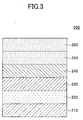
- Fig. 3 illustrates a configuration of a low-E glass.
- a low-E glass 200 illustrated in Fig. 3 includes a glass substrate 210, a first layer 220, a second layer 230, a third layer 240, a fourth layer 250, and a fifth layer 260, layered in this order.
- the first layer 220 is placed for improving the adhesiveness between the glass substrate 210 and the second layer 230 and for improving the transmittance in the visible light region of the Low-E glass 200.
- the first layer 220 may include, for example, a metal nitride, a metal oxide, and/or a metal oxynitride.
- the second layer 230 has a role of significantly reflecting solar light in a long wavelength region (more specifically, a wavelength region that is greater than or equal to 800 nm) and further reducing emissivity, the second layer 230 includes a metal reflective film.
- the third layer 240 has a role of preventing oxygen in the atmosphere from spreading into the second layer 230 when depositing the fourth layer 250.
- the third layer 240 may include, for example, a metal film, a metal nitride film, a metal oxide film, or a metal oxynitride film.
- the third layer 240 is not a requisite member and may be omitted in some cases.
- the fourth layer 250 is formed as a film for preventing oxidization of the second layer 230 and the third layer 240.
- the fourth layer 250 includes a protective film made of silica (silica film).
- the fifth layer 260 is formed as a dielectric film having a high refractive index.
- the transmittance of visible light in the entire low-E glass 200 can be improved.
- the reflectance of solar light in the long wavelength range (more specifically, a wavelength range that is greater than or equal to 800 nm) of the low-E glass 200 can be significantly increased.
- the fifth layer 260 is formed for improving scratch resistance.
- the low-E glass 200 includes a part corresponding to the "basic structure of the reflective member of the present invention" described above with reference to Fig. 1 . That is, the glass substrate 210, the second layer 230, and the fourth layer 250 of the low-E glass 200 correspond to the glass substrate 110, the metal reflective film 120, and the protective film 130 of the reflective member 100 of Fig. 1 , respectively.
- the low-E glass obtained by the repeated configuration is roughly described below.
- the glass substrate, the first layer, the second layer, the third layer, the fourth layer, and the fifth layer illustrated in Fig. 3 are layered in this order.
- a sixth layer similar to the first layer of Fig. 3 including, for example, metal nitride, metal oxide, and/or metal oxynitride is formed on the fifth layer.
- a seventh layer similar to the second layer of Fig. 3 including a metal reflective film is formed on the sixth layer.
- an eighth layer similar to the third layer of Fig. 3 including a metal film, a metal nitride film, a metal oxide film, or a metal oxynitride film is formed on the seventh layer.
- the low-E glass including the repeated configuration may further have the first to fifth layers of Fig. 3 placed on top of a tenth layer in this order, so that the low-E glass can significantly reflect solar light in a long wavelength region (more specifically, a wavelength region that is greater than or equal to 800 nm) and further reduce emissivity.
- the low-E glass 200 may be produced by forming the first layer 220 by a sputtering method, forming the second layer 230 by a sputtering method, depositing the third layer 240 by a sputtering method, depositing the fourth layer 250 by a plasma CVD method, and depositing the fifth layer 260 by a sputtering method.
- the deposition pressure when depositing the fourth layer 250 by the plasma CVD method is less than or equal to 2 Pa. Alternatively, the deposition pressure may be less than or equal to 1 Pa.
- the first layer 220 has a role of improving the adhesiveness between the glass substrate 210 and the second layer 230 and further improving the transmittance in the visible light region of the low-E glass 200.
- a low-E glass having low emissivity can be produced.
- the reflectance of solar light in the long wavelength region improves at the second layer 130 and the transmittance in the visible light region also improves at the second layer 130.
- the third layer 240 may include an oxide film.
- the oxide film may include zinc oxide.
- the zinc oxide may be doped with at least one element selected from a group including aluminum, titanium, gallium, and tin.
- the oxide film may include titanium oxide.
- the metal layer may include zinc and be doped with at least one element selected from a group including titanium, aluminum, tin, and gallium.
- the third layer 240 may include a nitride layer.
- the third layer 240 may include at least one nitride film selected from a group including a silicon nitride film, an aluminum nitride film, a chrome nitride film, a nickel nitride film, and a titanium nitride film.
- the nitride layer may include oxygen.
- the third layer 240 may have a thickness ranging from, for example, 5 ⁇ to 150 ⁇ or from 5 ⁇ to 180 ⁇ .
- the third layer 240 is not a requisite member and may be omitted.
- the fourth layer 250 that is formed in a subsequent process includes the silica film having the above-described characteristics. Therefore, even in a case where the third layer 240 is omitted, the second layer 230 can be significantly prevented from being oxidized owing to the oxygen barrier property of the fourth layer 250.
- the silica film has an extinction coefficient "k" less than or equal to 1 ⁇ 10 -4 and a refractive index "n" greater than or equal to 1.466 at a wavelength of 632 nm. Further, the silica film has a carbon content less than or equal to 3 atomic %. Thereby, the fourth layer 250 can exhibit density, that is, an oxygen barrier property, and significantly prevent oxidization of the second layer 230. Thus, the heat resisting property of the low-E glass 200 can be increased even in a high temperature.
- the fifth layer 260 includes a material having a higher refractive index than the fourth layer 250.
- the fifth layer 260 may have optical constants such as a refractive index "n" greater than or equal to 1.7 and an extinction coefficient "k" less than or equal to 0.01 at a wavelength of 550 nm..
- the zinc oxide may be doped with at least one element selected from a group including aluminum, tin, and titanium.
- the tin oxide may be doped with zinc.
- silicon nitride or a titanium nitride may be deposited.
- the fifth layer 260 includes silicon nitride or titanium nitride
- the fifth layer 260 exhibits an effect of preventing the oxygen in the atmosphere from entering the inside of the low-E glass 200. Accordingly, in this case, the oxidization of the second layer is further prevented owing to the oxygen barrier effects of both the fourth layer 250 and the fifth layer 260.
- the silicon nitride may be doped with aluminum.
- the fifth layer 260 may have a thickness ranging from 50 ⁇ to 1500 ⁇ . Further, the fifth layer 260 may be formed of a single layer or multiple layers.
- a film including metal may be oxidized by oxygen on the atmosphere side of the low-E glass.
- the oxidization of metal occurs in the second layer 230 that has a direct effect on the reflection property of the low-E glass, the reflection property of the low-E glass is significantly degraded.
- the low-E glass 200 illustrated in Fig. 3 includes the "basic structure of the reflective member of the present invention". Therefore, in such a case, the oxygen on the atmosphere side can be significantly prevented from passing through the fourth layer 250 and reaching the second layer 230 owing to the above-described effect of the protective film, that is, the oxygen barrier property of the fourth layer 250.
- the low-E glass 200 Accordingly, with the low-E glass 200, oxidization of the second layer 230 can be significantly prevented even in a case of performing a thermal process for a strengthening process. Thereby, the reflection property of the low-E glass 200 can be significantly prevented from degrading.
- Fig. 4 is a schematic diagram illustrating a configuration of a mirror apparatus.
- a mirror apparatus 300 has a glass substrate 310, a first layer 320, a second layer 330, a third layer 340, a fourth layer 350, and a fifth layer 360 that are layered in this order.
- the first layer 320 is placed for increasing the adhesiveness between the glass substrate 310 and the second layer 330.
- the first layer 320 may include, for example, a metal nitride, a metal oxide, and/or a metal oxynitride.
- the first layer 320 is not a requisite member and may be omitted.
- the second layer 330 has a role of significantly reflecting light in a wavelength region of solar light.
- the second layer 330 includes a metal reflective film.
- the third layer 340 has a role of preventing the oxygen in the atmosphere from spreading to the second layer 330 when depositing the fourth layer 350.
- the third layer 330 is not a requisite member and may be omitted.
- the fourth layer 350 having a refractive index lower than the fifth layer 360 is formed as a low refractive index film.
- the fourth layer 350 includes a protective film made of silica (silica film).
- the fifth layer 360 having a refractive index higher than the fourth layer 350 is formed as a high refractive index film. By layering the fifth layer 360 having a high refractive index on the fourth layer 350 having a low refractive index, the reflectance of the entire mirror apparatus 300 can be significantly increased.
- the thickness of the glass substrate 310 is not limited in particular. However, from the aspect of strength or the aspect of usability, the thickness of the glass substrate 310 may, for example, range from 0.5 mm to 8.0 mm.
- the first layer 320 includes at least one selected from a group including a metal nitride, a metal oxide, and a metal oxynitride.
- the first layer 220 may include zinc oxide.
- the zinc oxide may be doped with at least one element in a group including aluminum, titanium, gallium, and tin.
- the second layer 330 is a layer including a metal reflective film, and the light reaching the second layer 330 is reflected at this layer.
- the third layer 340 has a role of preventing the oxygen in the atmosphere from spreading to the second layer 330 when depositing the fourth layer 350.
- the fourth layer 350 includes a material having a refractive index lower than the fifth layer 360.
- the fourth layer 350 includes a silica film.
- the silica film has an extinction coefficient "k" less than or equal to 1 ⁇ 10 -4 and a refractive index "n" greater than or equal to 1.466 at a wavelength of 632 nm. Further, the silica film has a carbon content less than or equal to 3 atomic %. Thereby, the fourth layer 350 can exhibit density, which means an oxygen barrier property, and increase the heat resisting property of the mirror apparatus 300 even in a high temperature.
- the fifth layer 360 includes a material having a higher refractive index than the fourth layer 250.
- the fifth layer 360 has optical constants such as a refractive index "n" greater than or equal to 1.7and an extinction coefficient "k" less than or equal to 0.01 at a wavelength of 550 nm..
- the material included in the fifth layer 360 is not limited in particular as long as the above-described conditions are satisfied.
- the fifth layer 360 may include, for example, silicon nitride, aluminum nitride, silicon oxynitride, aluminum oxynitride, niobium oxide, zirconium oxide, tantalum oxide, hafnium oxide, titanium oxide, zinc oxide, and/or tin oxide. Further, the fifth layer 360 may include a complex oxynitride.
- silicon nitride is preferable.
- the fifth layer 360 exhibits an effect of preventing the oxygen in the atmosphere from entering. Therefore, in this case, the oxygen barrier effects of both the fourth layer 350 and the fifth layer 360 further prevent the oxidization of the second layer.
- an applied example of a protective film according to an embodiment of the present invention has been described above by presenting the low-E glass 200 and the mirror apparatus 300 as examples thereof. It is, however, to be noted that the applied example of the protective film according to an embodiment of the present invention is not limited to the reflective member. That is, one of ordinary skill in the art can expressly understand that the protective film according to an embodiment of the present invention may also be applied to various apparatuses and members or the like that require a heat resisting property.
- sample 3 a sample for a preliminary test 2 having a first silica film, a titanium metal film, and a second silica film on the surface of a glass substrate (hereinafter referred to as "sample 3") was fabricated.
- the flow amount of oxygen is 236 sccm and the flow amount of TMDSO was 15 sccm when depositing the first and second silica films.
- the deposition pressure during the plasma CVD process was 0.35 Pa, and the plasma power (deposition power density) was 80 kW/m.
- the refractive index "n” and the extinction coefficient "k” of the second silica film of sample 3 were measured with the above-described method. As a result of the measurement, the refractive index "n” was 1.469 and an extinction coefficient "k” was less than 1 ⁇ 10 -7 at a wavelength of 632 nm. Further the carbon content of the second silica film was less than or equal to the detection limit.
- the deposition conditions of the first and second silica films were the same as the conditions for depositing the silica film of the above-described sample B of preliminary test 1. Therefore, the silica films have a refractive index "n" of 1.4611 and an extinction coefficient "k" less than 1 ⁇ 10 -7 , and a carbon content less than or equal to the detection limit.
- a second silica film was deposited on the titanium metal film by using a sputtering method.
- the deposition conditions of the second silica film were substantially the same as the deposition conditions of the first silica film.
- sample 5" a sample for the preliminary test 2 was fabricated (hereinafter referred to as "sample 5").
- the refractive index "n” and the extinction coefficient "k” of the second silica film of sample 5 were measured by the above-described method. As a result of the measurement, the refractive index "n” was 1.4602 and an extinction coefficient "k” was less than 1 ⁇ 10 -7 at a wavelength of 632 nm. Further the carbon content of the second silica film was less than or equal to the detection limit.
- Table 2 collectively shows the fabrication conditions, the refractive indices "n”, the extinction coefficients "k”, and the carbon content of the samples 1 to 5.
- Table 2 SAMPLE DEPOSITION METHOD OF 1 ST AND 2 ND SILICA FILMS DEPOSITION PRESSURE (Pa) DEPOSITION POWER DENSITY (kW/m) REFRACTIVE INDEX OF 2 ND SILICA FILM n EXTINCTION COEFFICIENT OF 2 ND SILICA FILM k C CONTENT OF 2 ND SILICA FILM (%) ⁇ Tv (%) 1 PLASMA CVD METHOD 0.47 20 1.4772 LESS THAN 1 ⁇ 10 -7 N.D.
- the initial sample has a titanium metal film interposed between silica films. Therefore, the "initial visible light transmittance Tv o " of each of the samples is comparatively low.
- the heat resisting properties of the samples can be evaluated by evaluating the change amount ⁇ tv of the visible light transmittance Tv before and after the thermal process. More specifically, the heat resisting property is more satisfactory, the less the change amount ⁇ Tv.
- samples 1 to 3 show that the change amount ⁇ Tv of the visible light transmittance Tv is significantly restrained compared to samples 4 and 5. That is, the change amount of samples 1 to 3 is less than or equal to approximately 25% whereas the change amount of samples 4 and 5 is greater than or equal to approximately 30 %. Because the oxygen barrier property of the silica film of samples 4 and 5 is unsatisfactory, the oxygen in the atmosphere reaches the titanium film and causes the titanium to oxidize during the thermal process.
- the samples 1 to 3 show that the silica film has a refractive index "n” of 1.4772, 1.4773, and 1.469, respectively.
- the samples 4 and 5 show that the silica film has a refractive index "n” of 1.4611 and 1.4602, respectively. Therefore, the difference of the change amount ⁇ Tv of the visible light transmittance Tv is due to the refractive index "n" of the silica film.
- the oxygen barrier property of the silica film improves and the heat resisting property of the sample improves when the refractive index exceeds 1.4611. Particularly, the sample is estimated to have a satisfactory heat resisting property when the refractive index of the silica film is greater than or equal to 1.467.
- the amount of carbon in the silica film for each of the samples is less than or equal to the detection limit, and that there is a positive relationship between the refractive index "n" and density.
- a low-E glass sample (low-E glass sample 1) was fabricated as follows.
- the glass substrate is a soda-lime glass having a dimension of 100 mm in height ⁇ 100 mm in width ⁇ 3 mm in thickness.
- a first layer (target thickness 30 nm), a second layer (target thickness 8.5 nm), a third layer (target thickness 3 nm), a fourth layer (target thickness 26 nm), and a fifth layer (target thickness 24 nm) were sequentially deposited on one surface of the glass substrate. Thereby, the low-E glass sample 1 having a layer configuration illustrated in Fig. 4 was fabricated.
- the first layer includes an aluminum doped zinc oxide.
- the second layer includes a silver alloy having a gold content of 1 % by mass.
- the third layer includes an aluminum doped zinc.
- the fourth layer includes silica.
- the fifth layer includes silicon nitride.
- the first to third layers, and the fifth layer were deposited by the following sputtering method.
- a silver alloy film was deposited on the glass substrate formed with the aluminum doped zinc oxide film by using a silver alloy target containing gold of 1 % by mass and performing a DC sputtering method thereon.
- An argon gas (flow rate of 200 sccm) was used as the sputtering gas.
- a power of 0.9 kW was supplied.
- an aluminum doped zinc film was deposited on the silver alloy film by using a zinc target doped with aluminum of 5 atomic % and performing a DC sputtering method thereon.
- An argon gas (flow rate 200 sccm) was used as the sputtering gas.
- a power of 0.05 kW was supplied.
- the fourth layer made of silica was deposited by performing a plasma CVD method.
- the conditions for performing the plasma CVD method were the same conditions used when depositing the first silica film in the above-described sample 3 of the preliminary test. Therefore, the fourth layer has a refractive index of 1.469 and extinction coefficient "k" less than 1 ⁇ 10 -7 at a wavelength of 632 nm, and a carbon content less than or equal to the detection limit.
- a silicon nitride film was deposited by using a metal silicon target (boron doped polycrystalline target, silicon content of 99.999 % by mass) and performing a pulse DC reactive sputtering method thereon.
- a nitrogen gas (flow rate of 60 sccm) and an argon gas (flow rate of 14 sccm) were used as the sputtering gas.
- a power of 1 kW was supplied, and the frequency was 20 kHz.
- a low-E glass sample (low-E glass sample 2) having a similar layer configuration as the low-E glass sample 1 was fabricated. However, the third layer (aluminum doped zinc film) of the low-E glass sample 2 had a thickness of 4.5 nm.
- the other deposition conditions were the same as the low-E glass sample 1.
- a low-E glass sample (low-E glass sample 3) having a similar layer configuration as the low-E glass sample 1 was fabricated. However, the third layer
- (aluminum doped zinc film) of the low-E glass sample 2 had a thickness of 6 nm.
- the other deposition conditions were the same as the low-E glass sample 1.
- a low-E glass sample (low-E glass sample 4) having a similar layer configuration as the low-E glass sample 1 was fabricated.
- the fourth layer of the low-E glass sample 4 was deposited by a sputtering method.
- the sputtering conditions were the same as the conditions used when depositing the first silica film of the above-described sample 5 of the preliminary test. Therefore, the fourth layer has a refractive index "n" of 1.4602 and an extinction coefficient "k" less than 1 ⁇ 10 -7 at a wavelength of 632 nm, and a carbon content less than or equal to the detection limit.
- the other deposition conditions were the same as the low-E glass sample 1.
- the other deposition conditions were the same as the low-E glass sample 1.
- a low-E glass sample (low-E glass sample 6) having a similar layer configuration as the low-E glass sample 4 was fabricated. However, the third layer (aluminum doped zinc film) of the low-E glass sample 6 had a thickness of 6 nm.
- Table 3 collectively shows the fabrication conditions of the fourth layer of the low-E glass samples 1 to 6 along with their refractive indices "n", extinction coefficients "k”, and carbon content.
- Table 3> LOW-E GLASS SAMPLE THICKNESS OF 3 RD LAYER (nm) DEPOSITION METHOD OF 4 TH LAYER DEPOSITION PRESSURE (Pa) DEPOSITION POWER DENSITY (kW/m) REFRACTIVE INDEX OF 4 TH LAYER n EXTINCTION COEFFICIENT OF 4 TH LAYER k C CONTENT OF 4 TH LAYER (%) SHEET RESISTANCE AFTER THERMAL PROCESS Rs ( ⁇ / ⁇ ) TRANSMITTANCE OF VISIBLE LIGHT AFTER THERMAL PROCESS Tv (%) ⁇ Tv (%) EMISSIVITY RATE AFTER THERMAL PROCESS ⁇ (%) HAZE RATE AFTER THERMAL PROCESS (%) 1 3 PLAS
- Heat resisting property tests were performed on the low-E glass samples 1 to 6.
- the heat resisting property test was conducted by performing a thermal process on each low-E glass sample for 3 minutes in an atmosphere of 730 °C.
- the sheet resistance, the emissivity, and the haze rate of each of the low-E glass samples were measured after performing the thermal process on each of the low-E glass samples.
- a sheet resistance measuring device manufactured by Delcom Instruments Inc., 717B Conductance monitor
- the sheet resistance Rs ( ⁇ /square) of the low-E glass sample increases as the second layer (and the third layer) oxidizes. Therefore, the value of the sheet resistance Rs can be used as an index for evaluating the protective property of the fourth layer.
- an emissivity measuring device manufactured by Japan Sensor Inc., TSS-5X was used to obtain the emissivity ⁇ (%) in the wavelength region of 2 ⁇ m to 22 ⁇ m.
- the emissivity ⁇ of the low-E glass sample increases as the second layer (and the third layer) oxidizes. Therefore, the value of the emissivity ⁇ can be used as an index for evaluating the protective property of the fourth layer.
- a haze rate measuring device manufactured by Suga Test Instruments Co., Ltd, Hz-2
- a double-beam method was performed with a D65 light source.
- the term "haze rate” refers to an index that quantitatively indicates the level in which haziness occurs in the sample.
- the second layer of the low-E glass sample is degraded by heat, the second layer tends to cohere. Therefore, the haze rate can be used as an index for evaluating the protective property of the fourth layer.
- the visible light transmittance Tv of each sample is measured by using a spectrophotometer (manufactured by Hitachi Ltd., U4100) with a similar method as the above-described preliminary test 2 to obtain the change amount ⁇ Tv of the visible light transmittance Tv of the samples before and after performing the thermal process.
- the ⁇ tv of the low-E glass samples increases as the second layer (and the third layer) oxidizes. Therefore, the ⁇ tv can be used as an index for evaluating the protective property of the silica film.
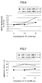
- Fig. 6 The results of measuring the sheet resistance after performing the thermal process on each of the low-E glass samples are shown in Fig. 6 .
- the horizontal axis indicates the thickness of the third layer
- the vertical axis indicates the sheet resistance Rs ( ⁇ /square).
- Fig. 7 The results of measuring the emissivity after performing the thermal process on each of the low-E glass samples are shown in Fig. 7 .
- the horizontal axis indicates the thickness of the third layer
- the vertical axis indicates the emissivity ⁇ (%).
- emissivity ⁇ (%) after performing the thermal process on the low-E glass samples 1 to 3 can be significantly restrained compared to those of the low-E glass samples 4 to 6.
- the fourth layer of the low-E glass samples 1 to 3 including the silica film exhibit a satisfactory oxygen barrier property.
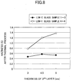
- Fig. 8 The results of measuring the haze rate after performing the thermal process on each of the low-E glass samples are shown in Fig. 8 .
- the horizontal axis indicates the thickness of the third layer, and the vertical axis indicates the haze rate (%).
- haze rate after performing the thermal process on the low-E glass samples 1 to 3 can be significantly restrained compared to those of the low-E glass samples 4 to 6.
- a low-E glass sample (low-E glass sample 7) was fabricated as follows.
- the glass substrate is a soda-lime glass having a dimension of 100 mm in height ⁇ 100 mm in width ⁇ 3 mm in thickness.
- a first layer (target thickness 30 nm), a second layer (target thickness 10 nm), a third layer (target thickness 10 nm), a fourth layer (target thickness 2 nm), and a fifth layer (target thickness 50 nm) were sequentially deposited on one surface of the glass substrate. Thereby, the low-E glass sample 7 having a layer configuration illustrated in Fig. 4 was fabricated.
- the first layer includes a tin zinc oxide film.
- the second layer includes an aluminum doped zinc oxide.
- the third layer includes silver.
- the fourth layer includes titanium.
- the fifth layer includes silica.
- the first to fourth layers were deposited by the following sputtering method.
- a tin zinc oxide film was deposited on the glass substrate by using an alloy target including zinc of 33 atomic % and tin of 67 atomic % and performing a DC reactive sputtering method thereon.
- An argon gas (flow rate of 120 sccm) and an oxygen gas (flow rate of 280 sccm) were used as the sputtering gas.
- a power of 1 kW was supplied, and the frequency was 20 kHz.
- an aluminum doped zinc oxide film was deposited on the tin zinc oxide film by using a zinc target doped with aluminum of 5 atomic % and performing a DC reactive sputtering method thereon.
- An argon gas (flow rate of 120 sccm) and an oxygen gas (flow rate of 280 sccm) were used as the sputtering gas.
- a power of 1 kW was supplied.
- a silver film was deposited on the aluminum doped zinc oxide film by using a silver target and performing a DC sputtering method thereon.
- An argon gas (flow rate of 400 sccm) was used as the sputtering gas.
- a power of 0.7 kW was supplied.
- a titanium metal film was deposited on the silver film by using a titanium metal target and performing a DC sputtering method thereon.
- An argon gas (flow rate of 400 sccm) was used as the sputtering gas.
- a power of 0.5 kW was supplied.
- the fifth layer made of silica was deposited by performing a plasma CVD method.
- a mixed gas of oxygen and tetramethyldisiloxane (TMDSO) was used as a raw material, in which the flow amount of oxygen was 250 sccm and the flow amount of TMDSO is 15 sccm. Further, the deposition pressure during the plasma CVD process was 0.23 Pa, and the deposition power density was 80 kW/m.
- the refractive index "n” and the extinction coefficient "k” of the silica film of the fifth layer were measured by the above-described method.
- the results of the measurement show that the silica film of the fifth layer has a refractive index "n” of 1.4736 and extinction coefficient "k” less than 1 ⁇ 10 -7 at a wavelength of 632 nm, and a carbon content that is less than or equal to the detection limit.
- a low-E glass sample (low-E glass sample 9) having a similar layer configuration as the low-E glass sample 7 was fabricated. However, the deposition pressure when depositing the fifth layer (silica film) of the low-E glass sample 9 was 0.51 Pa.
- the refractive index "n” and the extinction coefficient "k” of the silica film of the fifth layer (silica film) of the low-E glass sample 9 were measured by the above-described method. The results of the measurement show that the silica film of the fifth layer has a refractive index "n” of 1.4694 and extinction coefficient "k” less than 1 ⁇ 10 -7 at a wavelength of 632 nm, and a carbon content less than or equal to the detection limit.
- a low-E glass sample (low-E glass sample 10) having a similar layer configuration as the low-E glass sample 9. was fabricated. However, the fourth layer (titanium metal film) of the low-E glass sample 10 had a thickness of 6 nm.
- a low-E glass sample (low-E glass sample 11) was fabricated as follows.
- the glass substrate is a soda-lime glass having a dimension of 100 mm in height ⁇ 100 mm in width ⁇ 3 mm in thickness.
- a first layer (target thickness 30 nm), a second layer (target thickness 10 nm), a third layer (target thickness 10 nm), a fourth layer (target thickness 2 nm), a fifth layer (target thickness 20 nm), a sixth layer (target thickness 10 nm), and a seventh layer (target thickness 5 nm) were sequentially deposited on one surface of the glass substrate.
- the low-E glass sample 11 having a layer configuration illustrated in Fig. 4 was fabricated.
- the first layer includes a tin zinc oxide film.
- the second layer includes an aluminum doped zinc oxide.
- the third layer includes silver.
- the fourth layer includes titanium.
- the fifth layer includes silica.
- the sixth layer includes a tin zinc oxide film.
- the seventh layer includes silicon nitride.
- the first to fourth layers, the sixth layer, and the seventh layers were deposited by the following sputtering method.
- a tin zinc oxide film was deposited on the glass substrate by using an alloy target including zinc of 33 atomic % and tin of 67 atomic % and performing a DC pulse reactive sputtering method thereon.
- An argon gas (flow rate of 120 sccm) and an oxygen gas (flow rate of 280 sccm) were used as the sputtering gas.
- a power of 1 kW was supplied, and the frequency was 20 kHz.
- an aluminum doped zinc oxide film was deposited on the tin zinc oxide film by using a zinc target doped with aluminum of 5 atomic % and performing a DC reactive sputtering method thereon.
- An argon gas (flow rate of 120 sccm) and an oxygen gas (flow rate of 280 sccm) were used as the sputtering gas.
- a power of 1 kW was supplied.
- a silver film was deposited on the aluminum doped zinc oxide film by using a silver target and performing a DC sputtering method thereon.
- An argon gas (flow rate of 400 sccm) was used as the sputtering gas.
- a power of 0.7 kW was supplied.
- a titanium metal film was deposited on the silver film by using a titanium metal target and performing a DC sputtering method thereon.
- An argon gas (flow rate of 400 sccm) was used as the sputtering gas.
- a power of 0.5 kW was supplied.
- the fifth layer made of silica was deposited by performing a plasma CVD method.
- a mixed gas of oxygen and tetramethyldisiloxane (TMDSO) was used as a raw material, in which the flow amount of oxygen is 250 sccm and the flow amount of TMDSO is 15 sccm. Further, the deposition pressure during the plasma CVD process was 0.23 Pa, and the deposition power density was 80 kW/m.
- the refractive index "n” and the extinction coefficient "k” of the silica film of the fifth layer were measured by the above-described method.
- the results of the measurement show that the silica film of the fifth layer has a refractive index "n” of 1.4736 and extinction coefficient "k” less than 1 ⁇ 10 -7 at a wavelength of 632 nm, and a carbon content that is less than or equal to the detection limit.
- a tin zinc oxide film was deposited on the glass substrate by using an alloy target including zinc of 33 atomic % and tin of 67 atomic % and performing a DC pulse reactive sputtering method thereon.
- An argon gas (flow rate of 120 sccm) and an oxygen gas (flow rate of 280 sccm) were used as the sputtering gas.
- a power of 1 kW was supplied, and the frequency was 20 kHz.
- a silicon nitride film was deposited by using a metal silicon target (boron-doped polycrystalline target, silicon content of 99.999 % by mass) as a target and performing a pulse DC reactive sputtering method thereon.
- a nitrogen gas (flow rate of 120 sccm) and an argon gas (flow rate of 280 sccm) were used as the sputtering gas.
- a power of 1 kW was supplied, and the frequency was 20 kHz.
- the other deposition conditions were the same as the low-E glass sample 11.
- Table 4 collectively shows the fabrication conditions of the fifth layer of the low-E glass samples 7 to 12 along with their refractive indices "n", extinction coefficients "k”, and carbon content.
- Table 4> LOW-E GLASS SAMPLE THICKNESS OF 4 TH LAYER (nm) DEPOSITION METHOD OF 5 TH LAYER DEPOSITION PRESSURE (Pa) DEPOSITION POWER DENSITY (kW/m) REFRACTIVE INDEX OF 5 TH LAYER n EXTINCTION COEFFICIENT OF 5 TH LAYER k C CONTENT OF 5 TH LAYER (%) SHEET RESISTANCE AFTER THERMAL PROCESS Rs ( ⁇ / ⁇ ) TRANSMITTANCE OF VISIBLE LIGHT AFTER THERMAL PROCESS Tv (%) ⁇ Tv (%) EMISSIVITY RATE AFTER THERMAL PROCESS E (%) HAZE RATE AFTER THERMAL PROCESS (%) 7 2 PLASMA
- PLASMA CVD METHOD 0.23 80 1.4736 LESS THAN 1 ⁇ 10 -7 N.D. 6 65.2 11 0.12 0.48 9 2 PLASMA CVD METHOD 0.51 80 1.4694 LESS THAN 1 ⁇ 10 -7 N.D. 4.56 85.7 6.3 0.1 0.32 10 6 PLASMA CVD METHOD 0.51 80 1.4694 LESS THAN 1 ⁇ 10 -7 N.D. 6.1 67 14.2 0.12 0.27 11* 2 PLASMA CVD METHOD 0.23 80 1.4736 LESS THAN 1 ⁇ 10 -7 N.D.
- Heat resisting property tests were performed on the low-E glass samples 7 to 12.
- the heat resisting property test was conducted by performing a thermal process on each low-E glass sample for 3 minutes in an air atmosphere of 730 °C.
- the sheet resistance, the emissivity, and the haze rate of each of the low-E glass samples were measured after performing the thermal process on each of the low-E glass samples.
- a sheet resistance measuring device manufactured by Delcom Instruments Inc., 717B Conductance monitor was used.
- an emissivity measuring device manufactured by Japan Sensor Inc., TSS-5X was used to obtain the emissivity ⁇ (%) at the wavelength region of 2 ⁇ m to 22 ⁇ m.
- the sheet resistance Rs and the emissivity ⁇ of the low-E glass samples 7 to 12 increase as the third layer (and the fourth layer) oxidizes. Therefore, the sheet resistance Rs and the emissivity ⁇ can be used as indices for evaluating the protective property of the silica film.
- a haze rate measuring device manufactured by Suga Test Instruments Co., Ltd, Hz-2
- a double-beam method was performed with a D65 light source.
- the term "haze rate” refers to an index that quantitatively indicates the level in which haziness occurs in the sample.
- the haze rate can be used as an index for evaluating the protective property of the silica film.
- the visible light transmittance Tv of each sample was measured by using a spectrophotometer (manufactured by Hitachi Ltd., U4100) with a similar method as the above-described preliminary test 2 to obtain the change amount ⁇ Tv of the visible light transmittance Tv of the samples before and after performing the thermal process.
- the ⁇ Tv of the low-E glass samples 7 to 12 increases as the third and fourth layers oxidize. Therefore, the ⁇ Tv can be used as an index for evaluating the protective property of the silica film.
- emissivity ⁇ (%) after performing the thermal process on the low-E glass samples 7 to 12 can be significantly restrained compared to those of the low-E glass samples 4 to 6 in which the emissivity of each of the low-E glass samples 7 to 12 is less than 0.15.
- the fifth layer including the silica film of the low-E glass samples 7 to 12 exhibit a satisfactory oxygen barrier property.
- the third layer of the low-E glass samples 7 to 12 tend to exhibit less cohesiveness. That is, the third layer is not significantly degraded by the thermal process. Therefore, it can be understood that degradation by heat of the low-E glass samples 7 to 12 is restrained compared to those of the low-E glass samples 4 to 6.
- the low-E glass samples 7 to 12 including a silica layer having a refractive index "n" greater than or equal to 1.467 and an extinction coefficient "k" less than or equal to 1 ⁇ 10 -4 at a wavelength of 632 nm, and a carbon content less than or equal to 3 atomic %, a satisfactory oxygen barrier property can be attained compared to the low-E glass samples 4 to 6 having a fourth layer including a silica film having a refractive index "n" to a degree of 1.46.
- an aluminum doped zinc oxide film was deposited by using a zinc target doped with aluminum of 5 atomic % and performing a DC reactive sputtering method thereon.
- An argon gas (flow rate of 30 sccm) and an oxygen gas (flow rate of 70 sccm) were used as the sputtering gas.
- a power of 0.5 kW was supplied.
- the first to sixth layers were deposited by the following sputtering method.
- a silver film was deposited by using a silver target and performing a DC sputtering method thereon.
- An argon gas (flow rate of 100 sccm) was used as the sputtering gas.
- a power of 0.1 kW is supplied.
- a low-E glass sample (low-E glass sample 19) having a similar layer configuration as the low-E glass sample 18 was fabricated.
- the low-E glass sample 19 was fabricated to have a fifth layer having a target thickness of 14.5 nm, a sixth layer having a target thickness of 10 nm, and a seventh layer having a target thickness of 30 nm.
- the target thicknesses of the other layers were the same as those of the low-E glass sample 18.
- the sixth layer was a nitride film of nickel and aluminum.
- the nitride film of nickel and aluminum was deposited on the silver film by using an alloy target including nickel of 50% by mass and aluminum of 50% by mass and performing a pulse DC reactive sputtering method thereon.
- the other deposition conditions were the same as the low-E glass sample 18.
- Heat resisting property tests were performed on the low-E glass samples 15 to 20.
- the heat resisting property test was conducted by performing a thermal process on each low-E glass sample for 9 minutes in an air atmosphere of 730 °C.
- the third layers of samples 15 and 16 have a light absorption property because a nickel nitride is included in the third layer. However, when the third layer is oxidized by a thermal process, the light absorption property is reduced and becomes closer to a transparent film. However, because the fourth layer being provided on an upper part of the third layer and including a silica film has a satisfactory oxygen barrier property, the third layer is prevented from being oxidized during the thermal process to maintain its light absorption property. Thereby, the visible light transmittance Tv of samples 15 and 16 is less than or equal to 50% and the energy transmittance Te of samples 15 and 16 is less than or equal to 22% after the thermal process. Accordingly, it can be understood that the increase of transmittance due to oxidization of the third layer can be prevented. Further, the reflectance of the samples 15 and 16 is less than or equal to 20%. Accordingly, it can be understood that the reflectance can be maintained to be low in correspondence with the absorption of solar light.
- a silica film has a satisfactory oxygen barrier property when the refractive index "n" of the silica film exceeds 1.467.
- a mirror sample having a configuration of an actual mirror apparatus is fabricated. Further, the heat resisting property of each sample is evaluated.
- a mirror sample (mirror sample 1) was fabricated as follows.
- a glass substrate was prepared.
- the glass substrate has a dimension of 100 mm in height ⁇ 100 mm in width ⁇ 3 mm in thickness.
- the glass substrate is a non-alkali glass having a Na 2 O content of 0 % by mass.
- a first layer (target thickness 20 nm), a second layer (target thickness 120 nm), a third layer (target thickness 2.2 nm), a fourth layer (target thickness 50 nm), and a fifth layer (target thickness 50 nm) were sequentially deposited on one surface of the glass substrate.
- the mirror sample 1 having a layer configuration illustrated in Fig. 3 was fabricated.
- a silicon nitride film was deposited by using a metal silicon target (boron doped polycrystalline target, silicon content of 99.999 % by mass) and performing a pulse DC reactive sputtering method thereon.
- a nitride gas (flow rate of 60 sccm) and an argon gas (flow rate of 14 sccm) were used as the sputtering gas.
- a power of 1 kW was supplied, and the frequency was 20 kHz.
- a mirror sample including a similar layer configuration as the mirror sample 1 (mirror sample 2) was fabricated.
- the fourth layer of the mirror sample 2 was deposited by a plasma CVD method.
- the conditions for performing the plasma CVD method were the same conditions used when depositing the second silica film in the above-described sample 3 of the preliminary test 2. Therefore, the fourth layer has a refractive index "n" of 1.469 and an extinction coefficient "k" less than 1 ⁇ 10 -7 at a wavelength of 632 nm, and a carbon content less than or equal to the detection limit.
- a mirror sample including a similar layer configuration as the mirror sample 1 (mirror sample 3) was fabricated.
- the fourth layer (i.e., silica film) of the mirror sample 3 was deposited by a regular sputtering method.
- the conditions for performing the sputtering method were the same conditions used when depositing the second silica film in the above-described sample 5 of the preliminary test 2. Therefore, the fourth layer has a refractive index "n" of 1.4602 and an extinction coefficient "k" less than 1 ⁇ 10 -7 at a wavelength of 632 nm.
- the other deposition conditions are the same as the mirror sample 1.
- a mirror sample including a similar layer configuration as the mirror sample 3 (mirror sample 4) is fabricated.
- the fifth layer of the mirror sample 4 includes silicon nitride (target thickness of 50 nm) instead of titanium dioxide.
- the reflectance of solar energy Re of each mirror sample is measured after performing the thermal process on each mirror sample.
- the solar energy reflectance Re is a value that is calculated in conformity with ISO 9050-2003. More specifically, the solar energy reflectance Re refers to a weighted average obtained by multiplying the measured absolute spectral reflectance (300 nm to 2500 nm) with a weighting coefficient including an average spectral distribution of sunshine. Further, the appearance of each mirror sample after performing the thermal process is observed by visual inspection.
- the mirror samples 1 and 2 including a fourth layer having a silica film having a refractive index "n" that is greater than or equal to 1.466 and an extinction coefficient "k" that is less than or equal to 1 X 10 -4 in a wavelength region of 632 nm, and a carbon content that is less than or equal to 3 atomic %, a satisfactory heat resisting property can be attained compared to the mirror samples 3 and 4 including a fourth layer having a silica film having a refractive index "n” to a degree of 1.46.
- the present invention may be used, for example, in a low-E glass having low emissivity. Further, the present invention may be used, for example, in a secondary mirror of a linear Fresnel type or tower type solar power generation system.
Landscapes
- Chemical & Material Sciences (AREA)
- Engineering & Computer Science (AREA)
- Chemical Kinetics & Catalysis (AREA)
- Materials Engineering (AREA)
- Organic Chemistry (AREA)
- General Chemical & Material Sciences (AREA)
- Life Sciences & Earth Sciences (AREA)
- Geochemistry & Mineralogy (AREA)
- Physics & Mathematics (AREA)
- Mechanical Engineering (AREA)
- Metallurgy (AREA)
- Optics & Photonics (AREA)
- General Physics & Mathematics (AREA)
- Inorganic Chemistry (AREA)
- Plasma & Fusion (AREA)
- Health & Medical Sciences (AREA)
- Sustainable Development (AREA)
- Toxicology (AREA)
- Surface Treatment Of Glass (AREA)
- Optical Elements Other Than Lenses (AREA)
- Laminated Bodies (AREA)
- Physical Vapour Deposition (AREA)
Priority Applications (1)
| Application Number | Priority Date | Filing Date | Title |
|---|---|---|---|
| PL14797913T PL2998112T3 (pl) | 2013-05-14 | 2014-05-13 | Folia ochronna, środek odblaskowy i sposób wytwarzania folii ochronnej |
Applications Claiming Priority (2)
| Application Number | Priority Date | Filing Date | Title |
|---|---|---|---|
| JP2013102074 | 2013-05-14 | ||
| PCT/JP2014/062736 WO2014185420A1 (fr) | 2013-05-14 | 2014-05-13 | Film de protection, élément réfléchissant et procédé de fabrication du film de protection |
Publications (3)
| Publication Number | Publication Date |
|---|---|
| EP2998112A1 true EP2998112A1 (fr) | 2016-03-23 |
| EP2998112A4 EP2998112A4 (fr) | 2017-01-04 |
| EP2998112B1 EP2998112B1 (fr) | 2018-01-03 |
Family
ID=51898397
Family Applications (1)
| Application Number | Title | Priority Date | Filing Date |
|---|---|---|---|
| EP14797913.2A Active EP2998112B1 (fr) | 2013-05-14 | 2014-05-13 | Film de protection, élément réfléchissant et procédé de fabrication du film de protection |
Country Status (12)
| Country | Link |
|---|---|
| US (1) | US10634887B2 (fr) |
| EP (1) | EP2998112B1 (fr) |
| JP (1) | JP6299755B2 (fr) |
| EA (1) | EA030242B1 (fr) |
| ES (1) | ES2658046T3 (fr) |
| HU (1) | HUE038490T2 (fr) |
| MX (1) | MX2015015655A (fr) |
| MY (1) | MY181745A (fr) |
| PL (1) | PL2998112T3 (fr) |
| SA (1) | SA515370141B1 (fr) |
| TR (1) | TR201802321T4 (fr) |
| WO (1) | WO2014185420A1 (fr) |
Families Citing this family (13)
| Publication number | Priority date | Publication date | Assignee | Title |
|---|---|---|---|---|
| JP6433489B2 (ja) * | 2013-12-13 | 2018-12-05 | エージーシー グラス ユーロップAgc Glass Europe | 日射調整グレイジング |
| US9752377B2 (en) | 2015-03-20 | 2017-09-05 | Cardinal Cg Company | Nickel-aluminum blocker film controlled transmission coating |
| US9469566B2 (en) | 2015-03-20 | 2016-10-18 | Cardinal Cg Company | Nickel-aluminum blocker film low-emissivity coatings |
| US9745792B2 (en) | 2015-03-20 | 2017-08-29 | Cardinal Cg Company | Nickel-aluminum blocker film multiple cavity controlled transmission coating |
| RU2622281C1 (ru) * | 2016-01-29 | 2017-06-13 | Общество с ограниченной ответственностью "Пилкингтон Гласс" | Способ защитной олеофобной обработки тонкопленочных электропроводящих оптических покрытий на стекле |
| US11028012B2 (en) | 2018-10-31 | 2021-06-08 | Cardinal Cg Company | Low solar heat gain coatings, laminated glass assemblies, and methods of producing same |
| FR3088636B1 (fr) * | 2018-11-16 | 2022-09-09 | Saint Gobain | Materiau traite thermiquement a proprietes mecaniques ameliorees |
| FR3088635B1 (fr) * | 2018-11-16 | 2022-04-01 | Saint Gobain | Matériau traité thermiquement à faible résistivité et propriétés mécaniques améliorées |
| CN113728255B (zh) | 2019-03-28 | 2024-11-01 | 维特罗平板玻璃有限责任公司 | 可加热的风挡 |
| CA3167821A1 (fr) | 2020-02-14 | 2021-08-19 | Zhixun MA | Revetement a faible resistance de feuille |
| US11498867B2 (en) * | 2020-10-01 | 2022-11-15 | Guardian Glass, LLC | Coated article with IR reflecting layer designed for low u-value and higher g-value and method of making same |
| EP4382290A4 (fr) * | 2021-08-05 | 2025-07-30 | Shinetsu Chemical Co | Article ayant une couche de surface hydrofuge et oléofuge |
| CN116081959A (zh) * | 2023-02-24 | 2023-05-09 | 安徽省东超科技有限公司 | 镀膜玻璃及磁控溅射镀膜的方法 |
Family Cites Families (21)
| Publication number | Priority date | Publication date | Assignee | Title |
|---|---|---|---|---|
| JPS4928000B1 (fr) | 1970-11-02 | 1974-07-23 | ||
| IL86366A0 (en) * | 1988-05-12 | 1988-11-15 | Luz Ind Israel Ltd | Protected silvered substrates and mirrors containing the same |
| US5106671A (en) * | 1990-12-10 | 1992-04-21 | Ford Motor Company | Transparent anti-reflective coating |
| JP3319164B2 (ja) | 1994-08-01 | 2002-08-26 | 凸版印刷株式会社 | 透明ガスバリア材 |
| US5691044A (en) * | 1994-12-13 | 1997-11-25 | Asahi Glass Company, Ltd. | Light absorptive antireflector |
| US5991488A (en) * | 1996-11-08 | 1999-11-23 | The Arizona Board Of Regents On Behalf Of The University Of Arizona | Coupled plasmon-waveguide resonance spectroscopic device and method for measuring film properties |
| JP4013329B2 (ja) * | 1997-05-21 | 2007-11-28 | 旭硝子株式会社 | 積層体および窓用ガラス積層体 |
| JP2000017457A (ja) * | 1998-07-03 | 2000-01-18 | Shincron:Kk | 薄膜形成装置および薄膜形成方法 |
| US20020090521A1 (en) * | 2000-09-29 | 2002-07-11 | Tatsuji Nakajima | Silica layers and antireflection film using same |
| JP2002162510A (ja) * | 2000-11-22 | 2002-06-07 | Murakami Corp | 半透過型高反射膜 |
| US7232615B2 (en) | 2001-10-22 | 2007-06-19 | Ppg Industries Ohio, Inc. | Coating stack comprising a layer of barrier coating |
| KR20050001425A (ko) | 2003-06-27 | 2005-01-06 | 아사히 가라스 가부시키가이샤 | 고반사경 |
| JP2006010930A (ja) * | 2003-06-27 | 2006-01-12 | Asahi Glass Co Ltd | 高反射鏡 |
| US20050238923A1 (en) | 2004-04-27 | 2005-10-27 | Thiel James P | Hybrid coating stack |
| FI118021B (fi) * | 2004-07-09 | 2007-05-31 | Chip Man Technologies Oy | Mikroskoopin valaisujärjestelmä |
| EP1752937A1 (fr) * | 2005-07-29 | 2007-02-14 | Research In Motion Limited | Système et méthode d'entrée chiffrée d'un numéro d'identification personnel d'une carte à circuit intégré |
| WO2007013269A1 (fr) | 2005-07-29 | 2007-02-01 | Asahi Glass Company, Limited | Corps stratifié destiné à un film réfléchissant |
| US20070178316A1 (en) * | 2006-01-30 | 2007-08-02 | Guardian Industries Corp. | First surface mirror with sol-gel applied protective coating for use in solar collector or the like |
| JP5251071B2 (ja) | 2007-10-22 | 2013-07-31 | 凸版印刷株式会社 | バリアフィルムおよびその製造方法 |
| CN102812385B (zh) * | 2010-03-29 | 2016-08-03 | 西门子聚集太阳能有限公司 | 用于反射阳光的前表面镜及其制备方法和应用 |
| US10358385B2 (en) * | 2013-05-30 | 2019-07-23 | Agc Glass Europe | Solar control glazing |
-
2014
- 2014-05-13 EP EP14797913.2A patent/EP2998112B1/fr active Active
- 2014-05-13 MY MYPI2015002737A patent/MY181745A/en unknown
- 2014-05-13 ES ES14797913.2T patent/ES2658046T3/es active Active
- 2014-05-13 MX MX2015015655A patent/MX2015015655A/es unknown
- 2014-05-13 HU HUE14797913A patent/HUE038490T2/hu unknown
- 2014-05-13 PL PL14797913T patent/PL2998112T3/pl unknown
- 2014-05-13 JP JP2015517093A patent/JP6299755B2/ja active Active
- 2014-05-13 WO PCT/JP2014/062736 patent/WO2014185420A1/fr not_active Ceased
- 2014-05-13 EA EA201592165A patent/EA030242B1/ru not_active IP Right Cessation
- 2014-05-13 TR TR2018/02321T patent/TR201802321T4/tr unknown
-
2015
- 2015-11-12 SA SA515370141A patent/SA515370141B1/ar unknown
- 2015-11-13 US US14/941,354 patent/US10634887B2/en active Active
Also Published As
| Publication number | Publication date |
|---|---|
| EA030242B1 (ru) | 2018-07-31 |
| PL2998112T3 (pl) | 2018-08-31 |
| MX2015015655A (es) | 2016-06-23 |
| WO2014185420A1 (fr) | 2014-11-20 |
| MY181745A (en) | 2021-01-06 |
| US10634887B2 (en) | 2020-04-28 |
| HUE038490T2 (hu) | 2018-10-29 |
| EA201592165A1 (ru) | 2016-04-29 |
| JP6299755B2 (ja) | 2018-03-28 |
| EP2998112A4 (fr) | 2017-01-04 |
| SA515370141B1 (ar) | 2019-04-10 |
| EP2998112B1 (fr) | 2018-01-03 |
| ES2658046T3 (es) | 2018-03-08 |
| TR201802321T4 (tr) | 2018-03-21 |
| JPWO2014185420A1 (ja) | 2017-02-23 |
| US20160077320A1 (en) | 2016-03-17 |
Similar Documents
| Publication | Publication Date | Title |
|---|---|---|
| EP2998112B1 (fr) | Film de protection, élément réfléchissant et procédé de fabrication du film de protection | |
| CN1747907B (zh) | 载有涂层叠层的玻璃板 | |
| EP2480509B1 (fr) | Verre à faible émissivité comprenant une couche diélectrique, et son procédé de production | |
| EP3511505B1 (fr) | Matériau de construction fonctionnel pour fenêtres et portes | |
| EP2952939A1 (fr) | Procédé de fabrication d'un film réfléchissant le rayonnement infrarouge | |
| EP3081605B1 (fr) | Film de revêtement à faible émissivité, procédé de fabrication de celui-ci et matériau de construction fonctionnel pour fenêtres et portes comprenant celui-ci | |
| CN116002990A (zh) | 具有改善的阳光控制性能的阳光控制涂层 | |
| KR101768257B1 (ko) | 저방사 코팅 및 이를 포함하는 창호용 건축 자재 | |
| EP2276710A1 (fr) | Vitrage a controle solaire | |
| US11319245B2 (en) | Coated protective glazing | |
| EP3396454B1 (fr) | Écran transparent réfléchissant | |
| CN105705474B (zh) | 包含用含有银基功能层和厚TiOx下阻挡层的堆叠体涂覆的基材的窗玻璃 | |
| KR102940765B1 (ko) | 적층된 글레이징을 위한 태양광 제어 코팅 | |
| RU2578071C1 (ru) | Ir-отражающая и прозрачная система слоев, имеющая стабильную окраску, и способ ее изготовления, стеклоблок | |
| EP1845392A1 (fr) | Substrat ayant un revêtement antireflet | |
| JP6092882B2 (ja) | NiCu含有合金の層を含む日射調整グレージング | |
| KR20150069534A (ko) | 저방사 코팅막, 이의 제조방법 및 이를 포함하는 창호용 기능성 건축 자재 | |
| US9296651B2 (en) | Heat stable SnAl and SnMg based dielectrics | |
| JP2014178401A (ja) | 反射性部材、太陽熱発電システム用の二次ミラー、および反射性部材の製造方法 | |
| EP2991827B1 (fr) | Vitrage de controle solaire comprenant une couche d'un alliage de zinc et de cuivre | |
| JP2025531178A (ja) | 光吸収材料を含むマグネトロンスパッタリング蒸着コーティング組成物 | |
| KR20230166373A (ko) | 박막 다층 코팅이 구비된 투명 기재 및 이를 포함하는 다중 글레이징 유닛 | |
| Zoubian et al. | Potential of TaOxNy thin films deposited by reactive sputtering as antireflective coatings: composition and optical properties |
Legal Events
| Date | Code | Title | Description |
|---|---|---|---|
| PUAI | Public reference made under article 153(3) epc to a published international application that has entered the european phase |
Free format text: ORIGINAL CODE: 0009012 |
|
| 17P | Request for examination filed |
Effective date: 20151119 |
|
| AK | Designated contracting states |
Kind code of ref document: A1 Designated state(s): AL AT BE BG CH CY CZ DE DK EE ES FI FR GB GR HR HU IE IS IT LI LT LU LV MC MK MT NL NO PL PT RO RS SE SI SK SM TR |
|
| AX | Request for extension of the european patent |
Extension state: BA ME |
|
| DAX | Request for extension of the european patent (deleted) | ||
| A4 | Supplementary search report drawn up and despatched |
Effective date: 20161206 |
|
| RIC1 | Information provided on ipc code assigned before grant |
Ipc: C23C 14/18 20060101ALI20161130BHEP Ipc: G02B 5/08 20060101ALI20161130BHEP Ipc: C23C 16/42 20060101ALI20161130BHEP Ipc: C23C 14/34 20060101ALI20161130BHEP Ipc: G02B 19/00 20060101ALI20161130BHEP Ipc: G02B 1/14 20150101ALI20161130BHEP Ipc: C03C 17/09 20060101ALI20161130BHEP Ipc: C23C 14/06 20060101ALI20161130BHEP Ipc: C23C 14/10 20060101ALI20161130BHEP Ipc: G02B 1/10 20060101ALI20161130BHEP Ipc: C23C 16/50 20060101ALI20161130BHEP Ipc: C23C 16/40 20060101ALI20161130BHEP Ipc: B32B 9/00 20060101AFI20161130BHEP Ipc: C03C 17/36 20060101ALI20161130BHEP Ipc: C23C 14/16 20060101ALI20161130BHEP |
|
| GRAP | Despatch of communication of intention to grant a patent |
Free format text: ORIGINAL CODE: EPIDOSNIGR1 |
|
| INTG | Intention to grant announced |
Effective date: 20170825 |
|
| GRAS | Grant fee paid |
Free format text: ORIGINAL CODE: EPIDOSNIGR3 |
|
| GRAA | (expected) grant |
Free format text: ORIGINAL CODE: 0009210 |
|
| RIN1 | Information on inventor provided before grant (corrected) |
Inventor name: HANEKAWA, HIROSHI Inventor name: OKADA, NAOKO Inventor name: AOMINE, NOBUTAKA Inventor name: KAWAHARA, HIROTOMO |
|
| AK | Designated contracting states |
Kind code of ref document: B1 Designated state(s): AL AT BE BG CH CY CZ DE DK EE ES FI FR GB GR HR HU IE IS IT LI LT LU LV MC MK MT NL NO PL PT RO RS SE SI SK SM TR |
|
| REG | Reference to a national code |
Ref country code: GB Ref legal event code: FG4D |
|
| REG | Reference to a national code |
Ref country code: CH Ref legal event code: EP Ref country code: AT Ref legal event code: REF Ref document number: 959833 Country of ref document: AT Kind code of ref document: T Effective date: 20180115 |
|
| REG | Reference to a national code |
Ref country code: IE Ref legal event code: FG4D |
|
| REG | Reference to a national code |
Ref country code: DE Ref legal event code: R096 Ref document number: 602014019492 Country of ref document: DE |
|
| REG | Reference to a national code |
Ref country code: RO Ref legal event code: EPE |
|
| REG | Reference to a national code |
Ref country code: NL Ref legal event code: FP |
|
| REG | Reference to a national code |
Ref country code: ES Ref legal event code: FG2A Ref document number: 2658046 Country of ref document: ES Kind code of ref document: T3 Effective date: 20180308 |
|
| REG | Reference to a national code |
Ref country code: FR Ref legal event code: PLFP Year of fee payment: 5 |
|
| REG | Reference to a national code |
Ref country code: LT Ref legal event code: MG4D |
|
| REG | Reference to a national code |
Ref country code: AT Ref legal event code: MK05 Ref document number: 959833 Country of ref document: AT Kind code of ref document: T Effective date: 20180103 |
|
| PG25 | Lapsed in a contracting state [announced via postgrant information from national office to epo] |
Ref country code: CY Free format text: LAPSE BECAUSE OF FAILURE TO SUBMIT A TRANSLATION OF THE DESCRIPTION OR TO PAY THE FEE WITHIN THE PRESCRIBED TIME-LIMIT Effective date: 20180103 Ref country code: NO Free format text: LAPSE BECAUSE OF FAILURE TO SUBMIT A TRANSLATION OF THE DESCRIPTION OR TO PAY THE FEE WITHIN THE PRESCRIBED TIME-LIMIT Effective date: 20180403 Ref country code: HR Free format text: LAPSE BECAUSE OF FAILURE TO SUBMIT A TRANSLATION OF THE DESCRIPTION OR TO PAY THE FEE WITHIN THE PRESCRIBED TIME-LIMIT Effective date: 20180103 Ref country code: FI Free format text: LAPSE BECAUSE OF FAILURE TO SUBMIT A TRANSLATION OF THE DESCRIPTION OR TO PAY THE FEE WITHIN THE PRESCRIBED TIME-LIMIT Effective date: 20180103 Ref country code: LT Free format text: LAPSE BECAUSE OF FAILURE TO SUBMIT A TRANSLATION OF THE DESCRIPTION OR TO PAY THE FEE WITHIN THE PRESCRIBED TIME-LIMIT Effective date: 20180103 |
|
| PG25 | Lapsed in a contracting state [announced via postgrant information from national office to epo] |
Ref country code: RS Free format text: LAPSE BECAUSE OF FAILURE TO SUBMIT A TRANSLATION OF THE DESCRIPTION OR TO PAY THE FEE WITHIN THE PRESCRIBED TIME-LIMIT Effective date: 20180103 Ref country code: SE Free format text: LAPSE BECAUSE OF FAILURE TO SUBMIT A TRANSLATION OF THE DESCRIPTION OR TO PAY THE FEE WITHIN THE PRESCRIBED TIME-LIMIT Effective date: 20180103 Ref country code: LV Free format text: LAPSE BECAUSE OF FAILURE TO SUBMIT A TRANSLATION OF THE DESCRIPTION OR TO PAY THE FEE WITHIN THE PRESCRIBED TIME-LIMIT Effective date: 20180103 Ref country code: AT Free format text: LAPSE BECAUSE OF FAILURE TO SUBMIT A TRANSLATION OF THE DESCRIPTION OR TO PAY THE FEE WITHIN THE PRESCRIBED TIME-LIMIT Effective date: 20180103 Ref country code: GR Free format text: LAPSE BECAUSE OF FAILURE TO SUBMIT A TRANSLATION OF THE DESCRIPTION OR TO PAY THE FEE WITHIN THE PRESCRIBED TIME-LIMIT Effective date: 20180404 Ref country code: BG Free format text: LAPSE BECAUSE OF FAILURE TO SUBMIT A TRANSLATION OF THE DESCRIPTION OR TO PAY THE FEE WITHIN THE PRESCRIBED TIME-LIMIT Effective date: 20180403 Ref country code: IS Free format text: LAPSE BECAUSE OF FAILURE TO SUBMIT A TRANSLATION OF THE DESCRIPTION OR TO PAY THE FEE WITHIN THE PRESCRIBED TIME-LIMIT Effective date: 20180503 |
|
| REG | Reference to a national code |
Ref country code: DE Ref legal event code: R082 Ref document number: 602014019492 Country of ref document: DE Representative=s name: MUELLER-BORE & PARTNER PATENTANWAELTE PARTG MB, DE Ref country code: DE Ref legal event code: R081 Ref document number: 602014019492 Country of ref document: DE Owner name: AGC INC., JP Free format text: FORMER OWNER: ASAHI GLASS COMPANY, LTD., TOKYO, JP |
|
| REG | Reference to a national code |
Ref country code: DE Ref legal event code: R097 Ref document number: 602014019492 Country of ref document: DE |
|
| REG | Reference to a national code |
Ref country code: NL Ref legal event code: PD Owner name: AGC INC.; JP Free format text: DETAILS ASSIGNMENT: CHANGE OF OWNER(S), CHANGE OF LEGAL ENTITY; FORMER OWNER NAME: ASAHI GLASS COMPANY, LIMITED Effective date: 20180815 |
|
| REG | Reference to a national code |
Ref country code: BE Ref legal event code: HC Owner name: AGC INC.; JP Free format text: DETAILS ASSIGNMENT: CHANGE OF OWNER(S), CHANGEMENT DE NOM DU PROPRIETAIRE; FORMER OWNER NAME: ASAHI GLASS COMPANY, LIMITED Effective date: 20180822 |
|
| REG | Reference to a national code |
Ref country code: HU Ref legal event code: AG4A Ref document number: E038490 Country of ref document: HU Ref country code: HU Ref legal event code: FH1C Free format text: FORMER REPRESENTATIVE(S): DANUBIA SZABADALMI ES JOGI IRODA KFT., HU Representative=s name: DANUBIA SZABADALMI ES JOGI IRODA KFT., HU Ref country code: HU Ref legal event code: GB9C Owner name: AGC INC., JP Free format text: FORMER OWNER(S): ASAHI GLASS COMPANY, LIMITED, JP |
|
| PG25 | Lapsed in a contracting state [announced via postgrant information from national office to epo] |
Ref country code: AL Free format text: LAPSE BECAUSE OF FAILURE TO SUBMIT A TRANSLATION OF THE DESCRIPTION OR TO PAY THE FEE WITHIN THE PRESCRIBED TIME-LIMIT Effective date: 20180103 Ref country code: EE Free format text: LAPSE BECAUSE OF FAILURE TO SUBMIT A TRANSLATION OF THE DESCRIPTION OR TO PAY THE FEE WITHIN THE PRESCRIBED TIME-LIMIT Effective date: 20180103 |
|
| PLBE | No opposition filed within time limit |
Free format text: ORIGINAL CODE: 0009261 |
|
| STAA | Information on the status of an ep patent application or granted ep patent |
Free format text: STATUS: NO OPPOSITION FILED WITHIN TIME LIMIT |
|
| REG | Reference to a national code |
Ref country code: LU Ref legal event code: HC Owner name: AGC INC.; JP Free format text: FORMER OWNER: ASAHI GLASS COMPANY, LIMITED Effective date: 20181002 |
|
| PG25 | Lapsed in a contracting state [announced via postgrant information from national office to epo] |
Ref country code: SK Free format text: LAPSE BECAUSE OF FAILURE TO SUBMIT A TRANSLATION OF THE DESCRIPTION OR TO PAY THE FEE WITHIN THE PRESCRIBED TIME-LIMIT Effective date: 20180103 Ref country code: DK Free format text: LAPSE BECAUSE OF FAILURE TO SUBMIT A TRANSLATION OF THE DESCRIPTION OR TO PAY THE FEE WITHIN THE PRESCRIBED TIME-LIMIT Effective date: 20180103 Ref country code: SM Free format text: LAPSE BECAUSE OF FAILURE TO SUBMIT A TRANSLATION OF THE DESCRIPTION OR TO PAY THE FEE WITHIN THE PRESCRIBED TIME-LIMIT Effective date: 20180103 |
|
| REG | Reference to a national code |
Ref country code: ES Ref legal event code: PC2A Owner name: AGC INC. Effective date: 20181204 |
|
| 26N | No opposition filed |
Effective date: 20181005 |
|
| REG | Reference to a national code |
Ref country code: CH Ref legal event code: PL |
|
| PG25 | Lapsed in a contracting state [announced via postgrant information from national office to epo] |
Ref country code: MC Free format text: LAPSE BECAUSE OF FAILURE TO SUBMIT A TRANSLATION OF THE DESCRIPTION OR TO PAY THE FEE WITHIN THE PRESCRIBED TIME-LIMIT Effective date: 20180103 |
|
| REG | Reference to a national code |
Ref country code: IE Ref legal event code: MM4A |
|
| PG25 | Lapsed in a contracting state [announced via postgrant information from national office to epo] |
Ref country code: SI Free format text: LAPSE BECAUSE OF FAILURE TO SUBMIT A TRANSLATION OF THE DESCRIPTION OR TO PAY THE FEE WITHIN THE PRESCRIBED TIME-LIMIT Effective date: 20180103 Ref country code: LI Free format text: LAPSE BECAUSE OF NON-PAYMENT OF DUE FEES Effective date: 20180531 Ref country code: CH Free format text: LAPSE BECAUSE OF NON-PAYMENT OF DUE FEES Effective date: 20180531 |
|
| PG25 | Lapsed in a contracting state [announced via postgrant information from national office to epo] |
Ref country code: IE Free format text: LAPSE BECAUSE OF NON-PAYMENT OF DUE FEES Effective date: 20180513 |
|
| PG25 | Lapsed in a contracting state [announced via postgrant information from national office to epo] |
Ref country code: MT Free format text: LAPSE BECAUSE OF NON-PAYMENT OF DUE FEES Effective date: 20180513 |
|
| PG25 | Lapsed in a contracting state [announced via postgrant information from national office to epo] |
Ref country code: PT Free format text: LAPSE BECAUSE OF FAILURE TO SUBMIT A TRANSLATION OF THE DESCRIPTION OR TO PAY THE FEE WITHIN THE PRESCRIBED TIME-LIMIT Effective date: 20180103 |
|
| PG25 | Lapsed in a contracting state [announced via postgrant information from national office to epo] |
Ref country code: MK Free format text: LAPSE BECAUSE OF NON-PAYMENT OF DUE FEES Effective date: 20180103 |
|
| PGFP | Annual fee paid to national office [announced via postgrant information from national office to epo] |
Ref country code: RO Payment date: 20230504 Year of fee payment: 10 |
|
| PGFP | Annual fee paid to national office [announced via postgrant information from national office to epo] |
Ref country code: HU Payment date: 20230523 Year of fee payment: 10 |
|
| P01 | Opt-out of the competence of the unified patent court (upc) registered |
Effective date: 20240131 |
|
| PG25 | Lapsed in a contracting state [announced via postgrant information from national office to epo] |
Ref country code: RO Free format text: LAPSE BECAUSE OF NON-PAYMENT OF DUE FEES Effective date: 20240513 |
|
| PG25 | Lapsed in a contracting state [announced via postgrant information from national office to epo] |
Ref country code: RO Free format text: LAPSE BECAUSE OF NON-PAYMENT OF DUE FEES Effective date: 20240513 |
|
| PG25 | Lapsed in a contracting state [announced via postgrant information from national office to epo] |
Ref country code: HU Free format text: LAPSE BECAUSE OF NON-PAYMENT OF DUE FEES Effective date: 20240514 |
|
| PGFP | Annual fee paid to national office [announced via postgrant information from national office to epo] |
Ref country code: NL Payment date: 20250521 Year of fee payment: 12 |
|
| PGFP | Annual fee paid to national office [announced via postgrant information from national office to epo] |
Ref country code: DE Payment date: 20250521 Year of fee payment: 12 Ref country code: PL Payment date: 20250505 Year of fee payment: 12 |
|
| PGFP | Annual fee paid to national office [announced via postgrant information from national office to epo] |
Ref country code: GB Payment date: 20250527 Year of fee payment: 12 Ref country code: ES Payment date: 20250627 Year of fee payment: 12 |
|
| PGFP | Annual fee paid to national office [announced via postgrant information from national office to epo] |
Ref country code: LU Payment date: 20250521 Year of fee payment: 12 Ref country code: BE Payment date: 20250521 Year of fee payment: 12 Ref country code: IT Payment date: 20250527 Year of fee payment: 12 |
|
| PGFP | Annual fee paid to national office [announced via postgrant information from national office to epo] |
Ref country code: FR Payment date: 20250528 Year of fee payment: 12 |
|
| PGFP | Annual fee paid to national office [announced via postgrant information from national office to epo] |
Ref country code: TR Payment date: 20250506 Year of fee payment: 12 |
|
| PGFP | Annual fee paid to national office [announced via postgrant information from national office to epo] |
Ref country code: CZ Payment date: 20250506 Year of fee payment: 12 |