EP2998182A1 - Unite d'entrainement pour une marche d'un vehicule sur rails, module de marche et vehicule sur rails dote d'un module de marche - Google Patents
Unite d'entrainement pour une marche d'un vehicule sur rails, module de marche et vehicule sur rails dote d'un module de marche Download PDFInfo
- Publication number
- EP2998182A1 EP2998182A1 EP15185702.6A EP15185702A EP2998182A1 EP 2998182 A1 EP2998182 A1 EP 2998182A1 EP 15185702 A EP15185702 A EP 15185702A EP 2998182 A1 EP2998182 A1 EP 2998182A1
- Authority
- EP
- European Patent Office
- Prior art keywords
- telescopic guide
- tread
- lifting rod
- drive
- linear drive
- Prior art date
- Legal status (The legal status is an assumption and is not a legal conclusion. Google has not performed a legal analysis and makes no representation as to the accuracy of the status listed.)
- Withdrawn
Links
- 230000033001 locomotion Effects 0.000 claims abstract description 33
- 238000006073 displacement reaction Methods 0.000 claims description 7
- 230000002093 peripheral effect Effects 0.000 claims 1
- 238000004891 communication Methods 0.000 description 3
- 238000001514 detection method Methods 0.000 description 2
- 230000007613 environmental effect Effects 0.000 description 2
- 238000010521 absorption reaction Methods 0.000 description 1
- 230000000694 effects Effects 0.000 description 1
- 238000005516 engineering process Methods 0.000 description 1
- 238000009434 installation Methods 0.000 description 1
- 230000003993 interaction Effects 0.000 description 1
- 230000009347 mechanical transmission Effects 0.000 description 1
- 238000012986 modification Methods 0.000 description 1
- 230000004048 modification Effects 0.000 description 1
- 238000000926 separation method Methods 0.000 description 1
Images

Classifications
-
- B—PERFORMING OPERATIONS; TRANSPORTING
- B61—RAILWAYS
- B61D—BODY DETAILS OR KINDS OF RAILWAY VEHICLES
- B61D23/00—Construction of steps for railway vehicles
- B61D23/02—Folding steps for railway vehicles, e.g. hand or mechanically actuated
- B61D23/025—Folding steps for railway vehicles, e.g. hand or mechanically actuated electrically or fluid actuated
Definitions
- the invention is in the field of rail vehicle technology and in particular relates to a drive unit for a tread of a rail vehicle.
- the invention also relates to a tread unit, as well as a rail vehicle with a tread unit.
- the DE 195 31 284 A1 describes a rail vehicle in which below a door a transverse to the carriage longitudinal axis displaceable control part is arranged. At the control part is acted upon by a first and second linear actuator tread surface hinged. The tread surface can be pivoted from a rest position located within the specified clearance gauge of the rail vehicle into a horizontal position which is at the same level as the vehicle floor of the rail vehicle.
- EP 0 940 315 B1 describes a movable step for rail vehicles, which is designed as a folding stage and is opened by means of an electric motor against the force of a step acting on the tread in the retraction spring.
- An armature brake is provided for the electric motor to hold the folding stage in the open position without having to energize the electric motor.
- the EP 1 826 063 A1 describes a transport vehicle having an access device movable relative to the chassis of the transport vehicle, which is moved between an extended position in which said access device is near a curb or a curb and a retracted position in which said access device has moved back under the vehicle chassis , is movable.
- the transport vehicle further comprises a transfer system for the access device, wherein the transfer system is filled with a gas and is movable in the manner of a bellows between a folded state and an opened state.
- the displacement system is connected to the access device such that the displacement system in its opened state, the access device in their brings out extended position and brings the access device in its retracted position in its folded state.
- EP 1 826 063 A1 requires a complex pneumatic system and a pressure-tight bellows. However, this is susceptible to mechanical damage.
- a drive unit in particular for a tread of a rail vehicle, has a linear drive and a telescopic guide.
- the linear drive comprises a housing and a push rod driven in an axial direction of movement relative to the housing.
- the telescopic guide comprises a relative to the housing of the linear drive fixed outer bearing and a relative to the outer bearing in an axial direction of the telescopic guide displaceable lifting rod.
- the lifting rod is displaceable by means of the push rod of the linear drive relative to the outer bearing in the axial direction.
- the axial direction of movement of the push rod is parallel to the axial direction of the Telescopic guide, and the lifting rod is supported for receiving forces acting perpendicular to the axial direction on the outer bearing of the telescopic guide.
- the telescopic guide serves to guide the lifting rod in the axial direction and to absorb the force acting on the lifting rod in the transverse or radial forces that occur in use of the tread, and to initiate the car body of the rail vehicle.
- the lifting rod is preferably held without play in the radial direction, wherein it is movable in the axial direction. The movement of the lifting rod can thereby be limited to a 1-dimensional movement in the axial direction.
- the linear drive In contrast to the telescopic guide, which absorbs the forces occurring when using the tread, the linear drive, however, has to absorb any external forces, since it only has the function to move the lifting rod in the axial direction.
- the linear drive can therefore be dimensioned smaller.
- the linear drive only has to apply a force which is sufficient to move the lifting rod together with the load-free tread on itself, possibly against an example mechanical return element.
- only axial forces act on the linear drive.
- the drive unit can therefore be regarded as a direct drive, since the linear movement of the linear drive is converted directly into the movement of the tread.
- the linear drive can for example be attached to the outer bearing of the telescopic guide and be supported by this.
- the housing of the linear drive can be fixed directly to the outer bearing of the telescopic guide or rigidly via corresponding retaining elements.
- the drive unit can then be used as a preassembled unit be provided for attachment to the car body.
- the drive unit may be detachably connected to the carbody or load-bearing structures to ensure easy interchangeability.
- the linear drive and the telescopic guide are each fastened individually, for example on the car body or load-bearing structures which are fixed to the car body.
- the linear drive is fixed relative to the outer bearing of the telescopic guide and thus allows movement of the lifting rod relative to the outer bearing.
- the drive unit is used for realizing the entry stroke for the driver, without being limited thereto.
- the linear drive is preferably an electric adjusting element, as a result of which complicated pneumatic or hydraulic drives are avoided.
- the linear drive can for example have a defined stroke in the axial direction of movement, wherein it can continue to allow for the push rod fixed predetermined holding positions or holding positions at any position in the axial direction of movement.
- the telescopic guide does not have to be closed, but can also be partially open.
- the outer bearing of the telescopic guide for example, comprise two mutually axially spaced plain bearings, which allow only a movement in the axial direction. These plain bearings can then be provided with corresponding attachment interfaces for attachment to the car body, or to load-bearing structures fixed to the car body.
- the outer bearing may also be a linear bearing, for example a linear plain bearing or a linear ball bearing.
- the telescopic guide typically the outer bearing, corresponding mounting interfaces for attachment to the car body or load-bearing structures that are fixed to the car body, on.
- the attachment interfaces are dimensioned so that they can initiate the forces occurring when using the tread in the car body or the load-bearing structures.
- the forces occurring during use of the tread lead in particular to tilting moments, which act on the outer bearing.
- the outer bearing and the mounting interfaces should therefore have sufficient dimensions and strength to safely initiate these tilting moments in the car body or the load-bearing structures.
- the linear drive and the telescopic guide are typically arranged one behind the other in the axial direction, and the axial direction of movement of the push rod and the axial direction of the telescopic guide, i. the direction of movement of the lifting rod, are parallel to each other.
- the push rod and the lifting rod are arranged coaxially with each other, since other than axial forces are avoided in the interaction of push rod and lift rod.
- a linear drive can simultaneously drive the lifting rods of two telescopic guides arranged parallel to one another.
- the linear drive and the telescopic guide - with respect to the respective extension and retraction direction and with respect to a normal operating position of the rail vehicle - mounted substantially in a horizontal manner under the floor of the car body.
- the movement of the push rod of the linear drive and the lifting rod of the telescopic guide during extension and retraction takes place substantially in a horizontal direction.
- the axial direction of movement of the push rod and the axial direction of the telescopic guide extend horizontally or horizontally, in particular substantially parallel to the floor of the rail vehicle.
- the push rod and the lifting rod can be connected to each other. But it is also possible that the push rod presses only dull against a push rod facing the end of the lifting rod. In this case, the linear drive only serves to "extend” the lifting rod. The “retracting” then takes place by a restoring element, which acts on the lifting rod and this pushes back together with the push rod.
- the outer bearing of the telescopic guide is an outer tube, which guides the lifting rod axially, wherein the push rod of the linear drive engages in the axial direction of the telescopic guide in the outer tube and moves the lifting rod in the outer tube.
- the telescopic guide can thus be formed for example in the form of a telescopic tube.
- the outer tube has at least one sliding bearing on an end facing away from the linear drive end, which holds the lifting rod radially substantially free of play, leads in the axial direction and receives radially acting on the lifting rod forces.
- the plain bearing can be, for example, consisting of two bearings plain bearing.
- the sliding bearing does not necessarily prevent rotation. However, it should allow virtually a backlash-free and load-bearing storage in the radial direction.
- the specific design of the sliding bearing depends inter alia on the cross section of the lifting rod. This may have a circular outer cross section according to one embodiment. An approximately rectangular cross-section, for example with rounded corners, is also possible.
- the telescopic guide comprises a restoring element, which counteracts a movement of the lifting rod during its displacement by the push rod.
- the restoring element may be, for example, a mechanical return element, for example in the form of a force accumulator.
- the return element serves to return the lifting rod and the push rod to their original position, i. retract the tread.
- the linear drive must therefore be designed only for one direction of movement. The provision is made via the return element, which stores the energy required for this purpose, for example in a spring element, which is tensioned by the movement of the push rod.
- the restoring element can be integrated, for example, in the telescopic rod, for example between outer bearing and lifting rod. It is also possible to provide the return element on the outside of the outer bearing or separately to the telescopic guide.
- the linear drive comprises an electromechanical holding brake to hold the push rod in any position. This allows the position of the tread to be chosen arbitrarily. In addition, so the push rod can be kept against the action of the return element. The linear drive can then be switched off.
- the electromechanical holding brake is configured such that the push rod is held in the extended position of the tread.
- the end position of the drive can be detected by an overcurrent detection by the to be overcome by the linear drive resistance is too large.
- a predefined tension of the restoring element can be set in the extended position.
- a stop may be provided, against which the push rod abuts in the extended position.
- the lifting rod counteracts the push rod and would push back the push rod, if either the electromechanical holding brake would not be present, or the linear drive is not de-energized.
- a return element can be dispensed with if the linear drive can securely hold the push rod in a predetermined position.
- the linear drive and / or the telescopic guide on a sensor for detecting a maximum allowable displacement of push rod and / or lifting rod.
- a maximum permissible displacement can be detected and thus the movement can be limited.
- the linear drive and / or the telescopic guide on a Endlagerschalter for detecting the correct return of push rod and / or lifting rod. This can ensure that in particular the lifting rod is completely returned to its original position and the tread is completely retracted again.
- the drive unit further has a control unit, which is connected to the linear drive and controls the linear drive.
- the control unit may also be connected to the repository switch and the sensor and detect and evaluate their output signals.
- the control unit can Have at least one communication interface for data exchange with higher-level control units of the rail vehicle.
- a tread unit on at least one drive unit and a tread which is rigidly connected to the lifting rod of the drive unit and which is movable by moving the lifting rod in the axial direction of the telescopic guide.
- the tread is guided by the drive unit in a linear movement and in particular led out laterally from the boundary profile of the rail vehicle and returned again.
- the arrangement of the tread unit can be carried out according to a further embodiment such that the linear drive and telescopic guide are arranged substantially horizontally aligned under the floor of the car body. The movement during extension and retraction of the treads thus takes place substantially in the horizontal direction, or in the axial direction.
- the tread unit on at least two drive units, which are arranged parallel to each other, wherein the tread rigidly connects the lifting rods of the two drive units together.
- the drive units may, according to one embodiment, preferably be designed such that a drive unit is sufficient for actuating the tread unit.
- the power of a drive unit is preferably sufficiently large to extend the tread against the action of all return elements.
- provided electromechanical holding brakes may be designed such that a holding brake is sufficient to keep the tread unit in the extended position.
- the tread is held by two spaced apart telescopic guides.
- the tread is arranged in the extended state outside of the rail vehicle, that projects beyond the boundary profile of the rail vehicle.
- the tread ie its outwardly facing side, directly adjoins the boundary profile and may form part of the outside of the rail vehicle.
- a rail vehicle comprises a car body, at least one door and a tread unit, wherein the one or more outer bearing of the telescopic guide or the telescopic guides are attached to the car body.
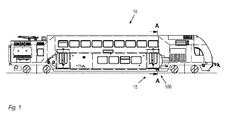
- Fig. 1 shows a rail vehicle 10 with a tread unit 100 according to an embodiment.
- the tread unit 100 is arranged below the passenger door 15 closest to the driver's seat.
- the tread unit 100 is used according to the present embodiment, the driver to allow entry and exit from the rail vehicle 10 outside of stations.
- the invention is not limited thereto, but can also be applied to treads for passengers.
- the tread is at a certain distance arranged below the floor 14 of the rail vehicle, since the tread does not serve for the exit to a platform but for the exit on, for example, free route.
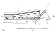
- Fig. 2 shows a section along the in Fig. 1 indicated line AA.
- the tread unit 100 comprises a linear drive 120 and a telescopic guide 110, which are arranged coaxially with each other.
- the telescopic guide 110 is attached to the body 13 of the rail vehicle 10, so that the force acting on the tread 50 forces can be absorbed by the car body 13.
- the linear drive 120 does not have to absorb any appreciable forces, since there is a separation between the drive and the bearing.
- Fig. 2 shows the tread unit 100 in the retracted and extended state.
- the tread 50 of the tread unit 100 is within the permissible boundary profile 12 of the rail vehicle 10.
- the tread 50 can form part of the outer contour of the rail vehicle 10 thereto.
- the tread 50 may have a panel which is flush with the surrounding outer contour of the rail vehicle 10, so that an aerodynamically substantially closed outer contour is formed.
- the telescopic guide 110 and the linear drive 120 are each individually on the car body 13 or attached to load-bearing structures that are fixed to the car body.
- the attachment can be designed so that the telescopic guide 110 and the linear actuator 120 - are arranged substantially horizontally with respect to their axial movement direction during extension and retraction -.
- the tread 50, and thus also the push rod 122 and the lifting rod 112 move according to Fig. 2 essentially in a horizontal direction, especially in the axial direction.
- Fig. 2 shows that the telescopic guide partially extends into an opening in the car body and, when the lifting rod is extended, the tread 50 brings to a position outside the boundary profile 12.
- the tread 50 may have at its end facing the car body 13 a stop 51 to define the end position of the tread 50 in the retracted state relative to the car body.
- Fig. 2 further shows that the tread 50 is spaced below the floor 14 of the rail vehicle. This makes it easier for the driver to enter or exit the open track. The tread 50 is therefore located below the platform edge and would not be used when stopping at a platform with platform edge at the level of the floor 14 in the door area 15.
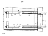
- Fig. 3 shows a tread unit comprising two drive units, each with a linear drive 120 and a telescopic guide 110.
- the push rods 122 of the linear drives 120 are removed in the fully retracted state of the lifting rods 112 and engage, when extending, in the outer bearing 111 of the respective telescopic guide 110, which here in Formed a pipe, a.
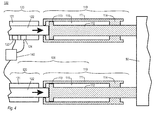
- FIG. 2 illustrates a sectional view through a tread unit 100, which comprises two drive units 101 arranged parallel to one another.
- the two drive units 101 are constructed identically in the present embodiment.
- the outer bearing 111 of the telescopic guide 110 is designed in the present embodiment as a tube which has a sliding bearing 114 at its end remote from the linear drive 120.
- This sliding bearing 114 axially guides the lifting rod 112 and holds it radially.
- the lifting rod 112 in turn has at its end facing the linear drive 120, a sliding shoe 113, which is axially slidably supported radially on the inner wall of the tubular outer bearing 111 and thus also supports the lifting rod 112 radially and axially.
- the inner wall of the tubular outer bearing 111 forms a sliding bearing for the sliding shoe 113.
- the outer bearing 111 of the telescopic guide 110 is fixed to the car body 13.
- the housing 121 of the linear drive 120 is likewise fastened to the carriage body 13, so that the housing 121 of the linear drive 120 is fixed relative to the outer bearing 111 of the telescopic guide 110.
- the housing 121 may also be attached directly to the outer bearing 111.
- the attachment interfaces may be, for example, clips connected integrally to the outer bearing or outer tube 111. It is also possible if the outer bearing or outer tube 111 individual load-absorbing structures, such as side members, passes through and is welded to these.
- the push rod 122 of the linear actuator 120 is arranged coaxially with the lifting rod 112 and pushes it towards the front slide bearing 114. This is the arrows in Fig. 4 indicated.
- the telescopic guide 110 may have a mechanical restoring element, not shown here, which is arranged, for example, within the outer bearing 111 and is supported between the outer bearing 111, specifically, for example, the sliding bearing 114, and the lifting rod 112, specifically, for example, the sliding shoe 113.
- the reset element acts with the arrow in Fig. 4 indicated movement of the push rod 122 against.
- the push rod 122 therefore performs work against the return element and supplies this energy, which stores the return element and to return the lift rod 112, and thus the push rod 122 uses.
- the restoring element is a spring element.
- the return element may also be a pneumatic return element.
- the telescopic guide 110 can also be referred to as a spring tube.
- the two lifting rods 112 are rigidly connected to the tread 50 at their front, remote from the respective linear drive 120 end.
- the tread 50 may, for example, comprise a bridge which establishes the actual rigid connection between the two lifting rods 112. A tread can then be connected to the bridge.
- the bridge may carry a part of the outer lining of the rail vehicle in the form of a panel.
- the tread unit 100 further comprises a control unit 140, a repository switch 123 and a holding brake 124.
- the holding brake 124 serves to hold the push rod 122 in a preferably arbitrary position against the return action of the return element. As a result, the linear drive 110 can be de-energized when the holding brake 124 is actuated.
- the control unit 140 can for this purpose have a communication interface for communication with higher-level control units.
- the repository switch 123 may also be provided in the telescopic guide 110 to directly detect the position of the lifting rod 112. This is particularly advantageous if the lifting rod 112 and the push rod 122 are not firmly connected.
- the tread unit 100 may further comprise a sensor which detects the position of the lifting rod 112 and / or the push rod 122, so as to determine the current position of the tread 50.
- the extension of the tread 50 can be set to different positions.
- the maximum position can also be determined by detecting the current which is supplied to the linear drive 120, since an overcurrent flows here when a mechanical resistance is reached by the linear drive 120.
- the sensor can therefore also be an overcurrent sensor.
- the drive units 101 can be used as a direct drive for the realization of the step for the driver, taking into account critical environmental conditions, in particular the boundary profile 12.
- the tread unit 100 may have in particular the control unit 140, two drive units 101 each having a linear drive 120, for example in the form of an electric adjuster with holding brake 124 and limit switch 123, and a telescopic guide 110 with mechanical reset unit, and the tread 50. It is also possible that only one drive unit 101 and one additional telescopic guide 110 are used, since for the extension of the tread 50 no large axial forces must be applied. The two telescopic guides 110 then serve to accommodate the tilting moments.
- linear drive 120 drives out the push rod 122, which thereby axially displaces the lifting rod 112. At the same time a biasing member acting on the lifting rod 112 is biased. The tread 50 moves out at the same time.
- An overcurrent detection of the linear drive 120 detects the end position and or possible foreign bodies in the effective range of the linear drive 120 and / or the tread 50.
- the electromagnetic holding brake 124 is actuated and the linear drive 120 can be de-energized.
- the step 50 is in the "extended" position.
- the supply voltage of the holding brake 124 is turned off, whereby the holding function of the holding brake 124 is terminated.
- the lifting rod 112 By means of the return element, the lifting rod 112, the push rod 122 and thereby also the tread 50 are retracted.
- the limit sensor 123 About the limit sensor 123, the end position is detected and the signal is given to the control unit 140.
- the tread unit may be redundant for safety reasons, i.
- Two drive units 101 are used.
- the mechanical connecting element for the lifting rods 112 is the step 50, whereby the movement of both drive units 101 takes place synchronously and the movement of a drive unit by means of the step 50 is also transmitted to a possibly failed drive unit. If, for example, a restoring element fails, the provision of both drive units 101, specifically the lifting rod 112 and the push rod 122, nevertheless takes place.
- the safe return of the tread 50 is done in total by the or the restoring elements, which are separate to the linear actuators 120.
- the position "safe retraction" can be detected via the repository switch 123 or other sensors, which are provided for example on the linear drive 120.
- Figs. 5A to 5C show various embodiments of telescopic guides.
- Fig. 5A shows an embodiment of a telescopic guide 110a with approximately rectangular cross-section with rounded corners of lift rod 112a and outer bearing 111a, which is present here as a pipe.
- Fig. 5B shows an embodiment of a telescopic guide 110b approximately round and in particular circular cross-section of lifting rod 112b and outer bearing 111b, which is also present here as a pipe.
- the lifting rods of in Figs. 5A and 5B embodiments shown are mounted by means of corresponding slide bearing (not shown) on the outer bearing.
- Fig. 5C shows an embodiment in which the lifting rod 112c is a partially open profile and is supported by running balls 118 or rollers against the inner wall of the tubular outer bearing 111c.
Landscapes
- Engineering & Computer Science (AREA)
- Mechanical Engineering (AREA)
- Platform Screen Doors And Railroad Systems (AREA)
Applications Claiming Priority (1)
| Application Number | Priority Date | Filing Date | Title |
|---|---|---|---|
| DE102014113423.0A DE102014113423A1 (de) | 2014-09-17 | 2014-09-17 | Antriebseinheit für eine Trittstufe eines Schienenfahrzeugs, Trittstufeneinheit, sowie Schienenfahrzeug mit einer Trittstufeneinheit |
Publications (1)
| Publication Number | Publication Date |
|---|---|
| EP2998182A1 true EP2998182A1 (fr) | 2016-03-23 |
Family
ID=54238201
Family Applications (1)
| Application Number | Title | Priority Date | Filing Date |
|---|---|---|---|
| EP15185702.6A Withdrawn EP2998182A1 (fr) | 2014-09-17 | 2015-09-17 | Unite d'entrainement pour une marche d'un vehicule sur rails, module de marche et vehicule sur rails dote d'un module de marche |
Country Status (2)
| Country | Link |
|---|---|
| EP (1) | EP2998182A1 (fr) |
| DE (1) | DE102014113423A1 (fr) |
Cited By (3)
| Publication number | Priority date | Publication date | Assignee | Title |
|---|---|---|---|---|
| CN108480950A (zh) * | 2018-05-24 | 2018-09-04 | 刘玉华 | 一种用于自动更换部件的设备 |
| WO2022012902A1 (fr) * | 2020-07-13 | 2022-01-20 | Siemens Mobility GmbH | Véhicule ferroviaire comprenant une marche extensible |
| EP4177128A1 (fr) | 2021-11-09 | 2023-05-10 | Stadler Rail AG | Dispositif d'embarquement pour l'embarquement dans un véhicule, véhicule comprenant un dispositif d'embarquement et procédé de franchissement d'une distance horizontale et/ou verticale entre un véhicule et une passerelle ou un quai |
Families Citing this family (2)
| Publication number | Priority date | Publication date | Assignee | Title |
|---|---|---|---|---|
| DE102015213233A1 (de) * | 2015-07-15 | 2017-01-19 | Bombardier Transportation Gmbh | Schienenfahrzeug mit einer Schiebetrittanordnung |
| AT519944B1 (de) * | 2017-05-11 | 2019-02-15 | Siemens Ag Oesterreich | Spaltüberbrückung |
Citations (9)
| Publication number | Priority date | Publication date | Assignee | Title |
|---|---|---|---|---|
| US969362A (en) * | 1909-09-18 | 1910-09-06 | Louise I Gregg | Auxiliary car-step. |
| DE4329614A1 (de) * | 1993-09-02 | 1995-03-09 | Uestra Hannoversche Verkehrsbe | Einstieg für Schienenfahrzeuge |
| DE19531284A1 (de) | 1995-08-25 | 1997-02-27 | Abb Patent Gmbh | Schienenfahrzeug für den Personenverkehr |
| KR20020062545A (ko) * | 2001-02-08 | 2002-07-26 | 소재형 | 지하철 안전발판 |
| EP0940315B1 (fr) | 1998-03-05 | 2003-10-15 | Knorr-Bremse Gesellschaft mit beschränkter Haftung | Marchepied amovible pour véhicules |
| EP1826063A1 (fr) | 2006-02-28 | 2007-08-29 | Iveco France S.A. | Véhicule de transport équipé d'un dispositif d'accès pour les personnes à mobilité réduite |
| GB2450712A (en) * | 2007-07-04 | 2009-01-07 | Cnh Uk Ltd | Vehicle having an elevated cab and access steps. |
| CN201227998Y (zh) * | 2008-02-25 | 2009-04-29 | 宣建民 | 列车伸缩梯板 |
| DE102012214089A1 (de) * | 2012-08-08 | 2014-02-13 | Siemens Aktiengesellschaft | Fahrzeug mit teleskopierbarer Einstiegsleiter |
-
2014
- 2014-09-17 DE DE102014113423.0A patent/DE102014113423A1/de not_active Withdrawn
-
2015
- 2015-09-17 EP EP15185702.6A patent/EP2998182A1/fr not_active Withdrawn
Patent Citations (9)
| Publication number | Priority date | Publication date | Assignee | Title |
|---|---|---|---|---|
| US969362A (en) * | 1909-09-18 | 1910-09-06 | Louise I Gregg | Auxiliary car-step. |
| DE4329614A1 (de) * | 1993-09-02 | 1995-03-09 | Uestra Hannoversche Verkehrsbe | Einstieg für Schienenfahrzeuge |
| DE19531284A1 (de) | 1995-08-25 | 1997-02-27 | Abb Patent Gmbh | Schienenfahrzeug für den Personenverkehr |
| EP0940315B1 (fr) | 1998-03-05 | 2003-10-15 | Knorr-Bremse Gesellschaft mit beschränkter Haftung | Marchepied amovible pour véhicules |
| KR20020062545A (ko) * | 2001-02-08 | 2002-07-26 | 소재형 | 지하철 안전발판 |
| EP1826063A1 (fr) | 2006-02-28 | 2007-08-29 | Iveco France S.A. | Véhicule de transport équipé d'un dispositif d'accès pour les personnes à mobilité réduite |
| GB2450712A (en) * | 2007-07-04 | 2009-01-07 | Cnh Uk Ltd | Vehicle having an elevated cab and access steps. |
| CN201227998Y (zh) * | 2008-02-25 | 2009-04-29 | 宣建民 | 列车伸缩梯板 |
| DE102012214089A1 (de) * | 2012-08-08 | 2014-02-13 | Siemens Aktiengesellschaft | Fahrzeug mit teleskopierbarer Einstiegsleiter |
Cited By (4)
| Publication number | Priority date | Publication date | Assignee | Title |
|---|---|---|---|---|
| CN108480950A (zh) * | 2018-05-24 | 2018-09-04 | 刘玉华 | 一种用于自动更换部件的设备 |
| CN108480950B (zh) * | 2018-05-24 | 2023-07-25 | 刘玉华 | 一种用于自动更换部件的设备 |
| WO2022012902A1 (fr) * | 2020-07-13 | 2022-01-20 | Siemens Mobility GmbH | Véhicule ferroviaire comprenant une marche extensible |
| EP4177128A1 (fr) | 2021-11-09 | 2023-05-10 | Stadler Rail AG | Dispositif d'embarquement pour l'embarquement dans un véhicule, véhicule comprenant un dispositif d'embarquement et procédé de franchissement d'une distance horizontale et/ou verticale entre un véhicule et une passerelle ou un quai |
Also Published As
| Publication number | Publication date |
|---|---|
| DE102014113423A1 (de) | 2016-03-17 |
Similar Documents
| Publication | Publication Date | Title |
|---|---|---|
| EP0943525B1 (fr) | Colonne de direction d'un véhicule automobile | |
| DE102007051971B4 (de) | Stellvorrichtung für Federungseinrichtungen | |
| EP1610994B1 (fr) | Marche coulissante | |
| DE102019217961A1 (de) | Lenksäulenanordnung | |
| EP2998182A1 (fr) | Unite d'entrainement pour une marche d'un vehicule sur rails, module de marche et vehicule sur rails dote d'un module de marche | |
| EP2862757B1 (fr) | Dispositif de réglage d'un volet avant et véhicule automobile associé | |
| EP2282904B1 (fr) | Système de protection du conducteur d'un véhicule | |
| DE102010029129A1 (de) | Verstellvorrichtung für Kraftfahrzeugsitze, insbesondere Höhenverstellvorrichtungen | |
| DE102018128014A1 (de) | Fußbedienpedal für ein Kraftfahrzeug mit autonomem und fahrergesteuertem Betriebsmodus | |
| EP1737709B1 (fr) | Dispositif pour assurer la protection de personnes, en cas de choc frontal au niveau d'une automobile, par levage du capot avant de ladite automobile | |
| DE102022134358B3 (de) | Dachmodul zur Bildung eines Fahrzeugdachs mit einer Verstellkinematik | |
| DE19531284A1 (de) | Schienenfahrzeug für den Personenverkehr | |
| EP4359256B1 (fr) | Dispositif de verrouillage de conteneur et procédé de verrouillage de conteneur | |
| AT516914A1 (de) | Verfahren und Einrichtung zur Zentrierung einer ungekuppelten Mittelpufferkupplung | |
| EP3554916B1 (fr) | Véhicule ferroviaire | |
| DE19607945C2 (de) | Wechselbehälter mit Stützbeinen | |
| EP3380382B1 (fr) | Sortie de secours frontale | |
| DE102013021803A1 (de) | Aufstieg zur Fahrzeugtür eines Kraftfahrzeugs | |
| EP1776257A1 (fr) | Systeme de protection en cas de retournement sur vehicules a toit escamotable | |
| DE102014013771A1 (de) | Verstelleinrichtung zum Anheben der Hinterkante einer Frontklappe eines Kraftfahrzeugs | |
| EP2050706B1 (fr) | Dispositif de fixation | |
| DE102020215468A1 (de) | Verstellsystem und Verfahren zur Längsverstellung eines Fahrzeugsitzes sowie Verwendung des Verfahrens | |
| EP3666719A1 (fr) | Dispositif automatique de blocage anti-déroulement | |
| DE10163386A1 (de) | Fensterheber mit einer Notschließeinrichtung für ein Kraftfahrzeug, insbesondere für ein Sicherheitsfahrzeug | |
| EP3177476A1 (fr) | Dispositif de pantographe, procédé de déplacement d'un dispositif de pantographe et utilisation d'un dispositif de pantographe |
Legal Events
| Date | Code | Title | Description |
|---|---|---|---|
| PUAI | Public reference made under article 153(3) epc to a published international application that has entered the european phase |
Free format text: ORIGINAL CODE: 0009012 |
|
| AK | Designated contracting states |
Kind code of ref document: A1 Designated state(s): AL AT BE BG CH CY CZ DE DK EE ES FI FR GB GR HR HU IE IS IT LI LT LU LV MC MK MT NL NO PL PT RO RS SE SI SK SM TR |
|
| AX | Request for extension of the european patent |
Extension state: BA ME |
|
| STAA | Information on the status of an ep patent application or granted ep patent |
Free format text: STATUS: THE APPLICATION IS DEEMED TO BE WITHDRAWN |
|
| 18D | Application deemed to be withdrawn |
Effective date: 20160924 |