EP2998218A1 - Aile d'un aéronef et aéronef comportant une telle aile - Google Patents
Aile d'un aéronef et aéronef comportant une telle aile Download PDFInfo
- Publication number
- EP2998218A1 EP2998218A1 EP14185039.6A EP14185039A EP2998218A1 EP 2998218 A1 EP2998218 A1 EP 2998218A1 EP 14185039 A EP14185039 A EP 14185039A EP 2998218 A1 EP2998218 A1 EP 2998218A1
- Authority
- EP
- European Patent Office
- Prior art keywords
- wing
- measured
- blade
- rear blade
- leading edge
- Prior art date
- Legal status (The legal status is an assumption and is not a legal conclusion. Google has not performed a legal analysis and makes no representation as to the accuracy of the status listed.)
- Withdrawn
Links
- 230000001419 dependent effect Effects 0.000 claims description 9
- 238000009826 distribution Methods 0.000 description 13
- 230000035939 shock Effects 0.000 description 6
- 238000004519 manufacturing process Methods 0.000 description 5
- 230000007704 transition Effects 0.000 description 5
- 230000008901 benefit Effects 0.000 description 4
- 230000010354 integration Effects 0.000 description 2
- 238000010924 continuous production Methods 0.000 description 1
- 230000002349 favourable effect Effects 0.000 description 1
- 238000005457 optimization Methods 0.000 description 1
Images


Classifications
-
- B—PERFORMING OPERATIONS; TRANSPORTING
- B64—AIRCRAFT; AVIATION; COSMONAUTICS
- B64C—AEROPLANES; HELICOPTERS
- B64C23/00—Influencing air flow over aircraft surfaces, not otherwise provided for
- B64C23/06—Influencing air flow over aircraft surfaces, not otherwise provided for by generating vortices
- B64C23/065—Influencing air flow over aircraft surfaces, not otherwise provided for by generating vortices at the wing tips
- B64C23/069—Influencing air flow over aircraft surfaces, not otherwise provided for by generating vortices at the wing tips using one or more wing tip airfoil devices, e.g. winglets, splines, wing tip fences or raked wingtips
-
- B—PERFORMING OPERATIONS; TRANSPORTING
- B64—AIRCRAFT; AVIATION; COSMONAUTICS
- B64C—AEROPLANES; HELICOPTERS
- B64C23/00—Influencing air flow over aircraft surfaces, not otherwise provided for
- B64C23/06—Influencing air flow over aircraft surfaces, not otherwise provided for by generating vortices
- B64C23/065—Influencing air flow over aircraft surfaces, not otherwise provided for by generating vortices at the wing tips
-
- Y—GENERAL TAGGING OF NEW TECHNOLOGICAL DEVELOPMENTS; GENERAL TAGGING OF CROSS-SECTIONAL TECHNOLOGIES SPANNING OVER SEVERAL SECTIONS OF THE IPC; TECHNICAL SUBJECTS COVERED BY FORMER USPC CROSS-REFERENCE ART COLLECTIONS [XRACs] AND DIGESTS
- Y02—TECHNOLOGIES OR APPLICATIONS FOR MITIGATION OR ADAPTATION AGAINST CLIMATE CHANGE
- Y02T—CLIMATE CHANGE MITIGATION TECHNOLOGIES RELATED TO TRANSPORTATION
- Y02T50/00—Aeronautics or air transport
- Y02T50/10—Drag reduction
Definitions
- the present invention relates to a wing for an aircraft, as well as to an aircraft comprising such a wing.
- the wing comprises a main wing and a wing tip device.
- the main wing includes any possible high-lift devices or ailerons.
- the main wing comprises a wing leading edge, a wing trailing edge opposite to said wing leading edge, a wing root end which is configured to be mounted to a fuselage of a respective aircraft, and a wing tip end opposite to said wing root end.
- the wing tip device has an attachment end, a front blade and a rear blade. The attachment end is attached to the wing tip end of the main wing.
- the front blade has a front blade leading edge and a front blade trailing edge.
- the rear blade has a rear blade leading edge and a rear blade trailing edge.
- the front blade and the rear blade extend away from the attachment end in a diverging manner, i. e. they do not extend entirely in a common plane, although they might have sections extending in a common plane.
- the front blade leading edge extends in front of the rear blade leading edge, and the front blade trailing edge extends in front of the rear blade trailing edge, when viewed in a chord direction.
- the front blade has a front blade tip
- the rear blade has a rear blade tip.
- tip caps are attached for rounding and protecting the front and rear blade tips.
- the front blade extends under a different dihedral angle than the rear blade at the rear blade tip so that the front blade tip extends on a different level than the rear blade tip, when viewed in a wing thickness direction or along a yaw axis of an associated aircraft.
- the dihedral angle in general is measured with reference to a pitch axis of an associated aircraft in a plane spanned by the pitch axis and the yaw axis, or with reference to a horizontal plane when said aircraft is in a regular position on the ground.
- the dihedral angles at the front and rear blade tips, as well as all other angles defined at the front and rear blade tips under the present invention, are measured at the front blade tip and at the rear blade tip, respectively, right before the beginning of the tip caps, i. e. at the connection line to the tip caps, in particular as a tangent to said connection line.
- the front blade leading edge and the front blade trailing edge both have a tangent-continuous developing without inflexion points or kinks.
- a tangent-continuous developing within the meaning of the present invention includes any continuously curved sections, as well as any straight sections which are connected to the continuously curved sections in such a manner that the developing of the tangent of the curved sections continuously transits into the straight sections, so that at the transition from the curved sections to the straight sections the tangent of the curved sections coincides with the straight sections.
- a tangent continuous developing excludes any kinks or discontinuities at the curved sections, straight sections, as well as at the transitions between curved and straight sections.
- the rear blade leading edge and the rear blade trailing edge both have a tangent-continuous developing without inflexion points or kinks.
- Wing tip devices in general are provided in the art in order to reduce the induced drag of a wing.
- Induced drag also called lift dependent drag, occurs when lift is produced.
- Lift is produced by the wing through accelerating air mass downwards downstream of the wing with a certain momentum change equivalent to the lift produced.
- the continuous production of momentum consumes energy equivalent to the lift dependent drag.
- Minimizing induced drag requires minimizing the downward air deflection per span unit.
- efficiency of the respective wing increases with higher span.
- non-planar wings with wingtip devices help further minimizing the lift dependent drag.
- Due to wing flexibility upward pointing devices reduce the effective span more than downward pointing elements. Combining both elements whilst still respecting the need for a constant downwash distribution far downstream of the wing through the right aerodynamic loading helps to maximize the benefit.
- a constant downwash distribution represents a general optimization goal in order to minimize the induced drag a wing.
- U.S. 2002/0162917 A1 discloses a wing comprising a wing tip device formed as a single blade which is curved upwards in a continuous manner.
- U.S. 2010/0919094 A1 describes a wing tip device including a single blade which is curved upwards in a continuous manner leading into a straight tip section.
- double-blade wing tip devices are known in the art.
- Richard T. Whitcomb developed a wing tip device which was later realized on the DC-10 and MD-11 aircraft.
- the wing tip device includes a small front blade which points downwards and a bigger rear blade which points upwards from the wing. Both blades are attached to the wing in a canted, discontinued manner which leads to an undesired complex flow in the junction region, in particular on the suction side of the wing, and consequently, undesired drag.
- U.S. 2013/0256460 A1 discloses two fully overlapping blades, one pointing upwards and one pointing downwards out of the wing plane.
- the blades are connected to the main wing by hard, discontinued junctions, thereby challenging the flow in these junction areas.
- both blades extend from a common root, so that they overlap over their entire span, which also causes undesired flow conditions.
- a wing tip device having two blades, wherein an upper blade extends in a continuous manner upwards from the tip of the main wing.
- the lower blade which is mounted to the upper blade in a fully overlapping manner, again extends away from the upper blade under a certain kink, i. e. in a discontinued manner, so that the flow in said kink area is undesirably challenged and drag is caused.
- U.S. 2013/0092797 A1 describes a similar wing tip device comprising an upper blade, which is formed continuously on the tip of the main wing and extends upwards in a straight way, and a smaller lower blade which is connected to the junction of the upper blade in a discontinued manner.
- the "Morphing Airplane” developed by NASA comprises a wing including a wing tip device having two blades pointing upwards under a similar dihedral angle, wherein said blades are formed with the wing in a continuous manner, wherein a front blade exists in front of a rear blade such far that, however, they do not overlap at all and the wing tip has an undesirable large extent in a chord direction, and, thus, an undesirable high weight at the wing tip.
- U.S. 2009/0084904 A1 describes a wing tip device having a front blade and a rear blade which are attached to the main wing in a subsequent manner, i.e. by a certain staggering. Yet, said staggering involves a gap between the front blade and the rear blade so that front and rear blade do not overlap at all. Further, again the front blade and the rear blade are attached to the main wing in a discontinued manner including kinks.
- the object of the present invention is to provide a wing for an aircraft, wherein for a predetermined span dimension the induced drag can be significantly reduced.
- the front blade leading edge extends tangent-continuously with the wing leading edge without any kink, i.e. the transition from the front blade leading edge to the wing leading edge extends tangent-continuously without any kink.
- the rear blade trailing edge extends tangent-continuously with the wing trailing edge without any kink, i.e. the transition from the rear blade trailing edge to the wing trailing edge extends tangent-continuously without any kink.
- the front blade trailing edge at least partially extends behind the rear blade leading edge, when viewed in a chord direction from the wing leading edge to the wing trailing edge, so that the front blade and the rear blade overlap one another in an overlapping area, when viewed in the wing thickness direction.
- the front blade trailing edge intersects, i.e. crosses, the rear blade leading edge, when viewed in the wing thickness direction, so that near the attachment end the front blade trailing edge extends behind the rear blade leading edge, thereby forming the overlapping area, and remote from the attachment end the front blade trailing edge extends in front of the rear blade leading edge, so that no overlapping is present here, when viewed in the chord direction.
- a particularly advantage flow condition can be established on the wing tip device.
- the front blade trailing edge does not intersect or cross the rear blade leading edge, when viewed in the wing thickness direction, so that along the entire front blade trailing edge and/or along the entire rear blade leading edge the front blade trailing edge extends behind the rear blade leading edge, thereby forming the overlapping area over their entire length, when viewed in the chord direction.
- a particularly advantage flow condition can be established on the wing tip device.
- the front blade and the rear blade have a common base section and separate tip sections.
- the base section which might have a significant or an insignificant extent in the span direction, is defined between the front blade leading edge, the rear blade trailing edge, the attachment end, and opposite to the attachment end a front blade root where a front blade tip section is rooted in the base section, and a rear blade root where a rear blade tip section is rooted in the base section.
- a junction line or junction zone is provided which represents the line or zone in which the front blade and the rear blade intersect or merge.
- the front blade and the rear blade are merged or joined to a common structure which then can be advantageously connected to the wing tip end of the main wing at the attachment end.
- the base section is formed insignificantly short in the span direction so that the separate blades, in particular the front blade tip section and the rear blade tip section, are directly or almost directly attached to the wing tip end.
- the front blade root and the rear blade root represent sections where the front blade and the rear blade, respectively, merge or join to form the common base section, and the junction line represents the between the front blade root and the rear blade root, connecting these roots, i.e. the line where the outline of these roots meet and overlap.
- the wing tip device is formed and attached to the main wing in the following manner.
- a sweep angle of the front blade leading edge when measured at the attachment end, corresponds to the sweep angle of the wing leading edge, when measured at the wing tip end, and preferably is between 25° and 45°. Any sweep angle within the meaning of the present invention is measured with respect to a pitch axis of an associated aircraft, when viewed in a horizontal plane, i.e. a plane spanned by the pitch axis and the roll axis of an associated aircraft.
- a sweep angle of the front blade trailing edge when measured at the front blade root, corresponds to an angle between the sweep angle of the wing trailing edge and the sweep angle of the wing leading edge, when measured at the wing tip end, and preferably is between 20° and 40°.
- a sweep angle of the rear blade leading edge when measured at the rear blade root, corresponds to an angle between the sweep angle of the wing leading edge and twice the sweep angle of the wing leading edge, when measured at the wing tip end, and preferably is between 25° and 45°.
- a sweep angle of the rear blade trailing edge when measured at the attachment end, corresponds to the sweep angle of the wing trailing edge, when measured at the wing tip end, and preferably is between 20° and 40°.
- a sweep angle of the front blade leading edge when measured at the front blade tip, corresponds to an angle between the sweep angle of the wing leading edge and twice the sweep angle of the wing leading edge, when measured at the wing tip end, and preferably is between 45° and 60°.
- a sweep angle of the front blade trailing edge when measured at the front blade tip, corresponds to an angle between the sweep angle of the wing trailing edge and twice the sweep angle of the wing leading edge, when measured at the wing tip end, and preferably is between 40° and 55°. Any sweep angle defined at the front blade tip or at the rear blade tip within the meaning of the resent invention is measured right before the beginning of the tip caps, i. e. at the connection line to the tip caps, in particular as a tangent to said connection line.
- a sweep angle of the rear blade leading edge when measured at the rear blade tip, corresponds to an angle between the sweep angle of the wing leading edge and twice the sweep angle of the wing leading edge, when measured at the wing tip end, and preferably is between 45° and 60°.
- a sweep angle of the rear blade trailing edge when measured at the rear blade tip, corresponds to an angle between the sweep angle of the wing trailing edge and twice the sweep angle of the wing trailing edge, when measured at the wing tip end, and preferably is between 40° and 55°.
- the wing tip device is formed in the following manner.
- the extent of the front blade in the chord direction, when measured at the front blade root is between 20% and 80%, preferably between 40% and 60%, of the extent of the wing tip device in the chord direction, when measured at the attachment end.
- the extent of the front blade in the chord direction, when measured at the front blade tip is between 10% and 40%, preferably between 15% and 30%, of the extent of the wing tip device in the chord direction, when measured at the attachment end.
- the extent of the rear blade in the chord direction, when measured at the rear blade root is between 20% and 80%, preferably between 40% and 60%, of the extent of the wing tip device in the chord direction, when measured at the attachment end
- the extent of the rear blade in the chord direction, when measured at the rear blade tip is between 10% and 40%, preferably between 15% and 30%, of the extent of the wing tip device in the chord direction, when measured at the attachment end.
- the wing tip device is formed in the following manner.
- the extent of the front blade in a span direction, when measured between the attachment end and the front blade tip is between 50% and 300%, preferably between 100% and 200%, of the extent of the wing tip device in the chord direction, when measured at the attachment end.
- the extent of the rear blade in a span direction, when measured between the attachment end and the rear blade tip is between 50% and 300%, preferably between 100% and 200%, of the extent of the wing tip device in the chord direction, when measured at the attachment end.
- the main wing defines a wing plane which is approximately flat, wherein the front blade extends downwards, i.e. points downwards, out of said wing plane and wherein the rear blade extends upwards, i.e. points upwards, out of said wing plane, with reference to the wing thickness direction, or the yaw axis of an associated aircraft.
- This configuration allows a natural meshing of the pressure distributions from the front blade upper side and rear blade lower side in the overlapping area.
- any leading edge device integration for instance a slat, can be easier.
- the shock topology on the wing tip device can be smoothly connected.
- the wing tip device is formed in the following manner.
- the extent of the overlapping area, when measured along the junction line, is between 5% and 30%, preferably between 15% and 25%, of the extent of the wing tip device in the chord direction, when measured at the attachment end.
- the dihedral angle of the front blade leading edge, when measured at the attachment end corresponds to the dihedral angle of the wing leading edge, when measured at the wing tip end.
- the dihedral angle of the rear blade trailing edge when measured at the attachment end, corresponds to the dihedral angle of the wing trailing edge, when measured at the wing tip end.
- Any dihedral angle within the meaning of the present invention is measured with respect to a pitch axis of an associated aircraft, when viewed in a vertical plane, i.e. a plane spanned by the pitch axis and the yaw axis of an associated aircraft.
- the dihedral angle of the front blade when measured at the front blade tip, is between -10° and -60°, preferably between -20° and -45°.
- the dihedral angle of the rear blade when measured at the rear blade tip, is between 30° and 90°, preferably between 45° and 70°.
- the junction angle between the front blade and the rear blade along the junction line, when measured at the rear blade leading edge is between 0° and 45°, preferably between 10° and 30°.
- the junction angle between the front blade and the rear blade along the junction line, when measured at the front blade trailing edge is between 45° and 100°, preferably between 50° and 80°.
- the main wing defines a wing plane which is approximately flat, wherein the front blade extends upwards, i.e. points upwards, out of said wing plane and wherein the rear blade extends downwards, i.e. points downwards, out of said wing plane, with reference to the wing thickness direction or the yaw axis of an associated aircraft.
- the shock topology on the wing tip device can be smoothly connected.
- the wing tip device is formed in the following manner.
- the extent of the overlapping area, when measured along the junction line, is between 5% and 25%, preferably between 10% and 15%, of the extent of the wing tip device in the chord direction, when measured at the attachment end.
- the dihedral angle of the front blade leading edge, when measured at the attachment end corresponds to the dihedral angle of the wing leading edge, when measured at the wing tip end.
- the dihedral angle of the rear blade trailing edge when measured at the attachment end, corresponds to the dihedral angle of the wing trailing edge, when measured at the wing tip end.
- the dihedral angle of the front blade when measured at the front blade tip, is between 30° and 90°, preferably between 45° and 70°.
- the dihedral angle of the rear blade when measured at the rear blade tip, is between-20° and -60°, preferably between -30° and -45°.
- the junction angle between the front blade and the rear blade along the junction line, when measured at the rear blade leading edge is between 0° and 45°, preferably between 10° and 30°.
- the junction angle between the front blade and the rear blade along the junction line, when measured at the front blade trailing edge is between 45° and 100°, preferably between 50° and 80°.
- the main wing defines a wing plane which is approximately flat, wherein the front blade extends approximately flat in said wing plane and wherein the rear blade extends upwards, i.e. points upwards, out of said wing plane, with reference to the wing thickness direction or the yaw axis of an associated aircraft.
- This configuration allows a natural meshing of the pressure distributions from the front blade upper side and rear blade lower side in the overlapping area.
- any leading edge device integration for instance a slat, can be easier.
- shock topology on the wing tip device can be smoothly connected.
- ground operation can be easier without downward pointing blades.
- the wing tip device is formed in the following manner.
- the extent of the overlapping area, when measured along the junction line, is between 5% and 15%, preferably between 5% and 10%, of the extent of the wing tip device in the chord direction, when measured at the attachment end.
- the dihedral angle of the front blade leading edge, when measured at the attachment end corresponds to the dihedral angle of the wing leading edge, when measured at the wing tip end.
- the dihedral angle of the rear blade trailing edge when measured at the attachment end, corresponds to the dihedral angle of the wing trailing edge, when measured at the wing tip end.
- the dihedral angle of the front blade when measured at the front blade tip, corresponds to the dihedral angle of the wing leading edge, when measured at the wing tip end.
- the dihedral angle of the rear blade when measured at the rear blade tip, is between 30° and 90°, preferably between 45° and 70°.
- the junction angle between the front blade and the rear blade along the junction line, when measured at the rear blade leading edge is between 0° and 45°, preferably between 10° and 30°.
- the junction angle between the front blade and the rear blade along the junction line, when measured at the front blade trailing edge is between 20° and 60°, preferably between 30° and 45°.
- a further aspect of the present invention relates to an aircraft comprising the wing according to any of the aforedescribed embodiments.
- the features and advantages described above in connection with the wing also apply for the aircraft.
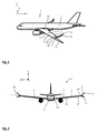
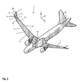
- the main wing 7 has a wing leading edge 11, a wing trailing edge 13 opposite to said wing leading edge 11, a wing root end 15 which is mounted to said fuselage 5, and a wing tip end 17 opposite to said wing root end 15.
- the wing tip device 9 has an attachment end 19 which is attached to the wing tip end 17 of the main wing 7, a front blade 21 having a front blade leading edge 23 and a front blade trailing edge 25, and a rear blade 27 having a rear blade leading edge 29 and a rear blade trailing edge 31.
- the front blade 21 and the rear blade 27 extend away from the attachment end 19 in a diverging manner.
- Front blade 21 and rear blade 27 are staggered, so that the front blade leading edge 23 extends in front of the rear blade leading edge 29 and the front blade trailing edge 25 extends in front of the rear blade trailing edge 31, when viewed in a chord direction 33 of the wing 3.
- the front blade 21 has a front blade tip 35 and the rear blade has a rear blade tip 37.
- Tip caps 39 are provided on front and rear blade tips 35, 37.
- the front blade 21 extends under a different dihedral angle ⁇ than the rear blade 27 at the rear blade tip 37, so that the front blade tip 35 extends on a different level than the rear blade tip 37, when viewed in a wing thickness direction 41.
- the dihedral angle ⁇ in general is measured with reference to a pitch axis p of an associated aircraft 1 in a plane spanned by the pitch axis p and the yaw axis y.
- the main wing 7 defines a wing plane 43 and the front blade 21 extends downwards out of said wing plane 43 while the rear blade 27 extends upwards out of said wing plane 43, with reference to the wing thickness direction 41.
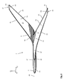
- the front blade leading edge 23 and the front blade trailing 25 edge both have a tangent-continuous, in the present embodiment a continuously curved, developing without inflexion points and kinks.
- the rear blade leading edge 29 and the rear blade trailing edge 31 both have a tangent-continuous, in the present embodiment a continuously curved, developing without inflexion points and kinks.
- the front blade leading edge 23 extends tangent-continuously with the wing leading edge 11 without a kink
- the rear blade trailing edge 31 extends tangent-continuously with the wing trailing edge 13 without a kink.
- the front blade trailing edge 25 at least partially extends behind the rear blade leading edge 29, when viewed in the chord direction 33 from the wing leading edge 11 to the wing trailing edge 13, so that the front blade 21 and the rear blade 27 overlap one another in an overlapping area 45, when viewed in the wing thickness direction 41.
- the front blade trailing edge 25 does not intersect the rear blade leading edge 29, when viewed in the wing thickness direction 41, so that along the entire rear blade leading edge 29 the front blade trailing edge 25 extends behind the rear blade leading edge 29, thereby forming the overlapping area 45 over the entire length of the rear blade leading edge 29, when viewed in the chord direction 33.
- the front blade trailing edge 25 does not intersect the rear blade leading edge 29, when viewed in the wing thickness direction 41, so that along the entire rear blade leading edge 29 the front blade trailing edge 25 extends behind the rear blade leading edge 29, thereby forming the overlapping area 45 over the entire length of the rear blade leading edge 29, when viewed in the chord direction 33.
- the front blade trailing edge 25 may also intersect the rear blade leading edge 29, when viewed in the wing thickness direction 41, so that near the attachment end 19 the front blade trailing edge 25 extends behind the rear blade leading edge 29, thereby forming the overlapping area 45, and remote from the attachment end 19 the front blade trailing edge 25 extends in front of the rear blade leading edge 29, when viewed in the chord direction 33.
- the front blade 21 and the rear blade 27 have a common base section 47 and separate tip sections 49, 51.
- the base section 47 is defined between the front blade leading edge 23, the rear blade trailing edge 31, the attachment end 19, and opposite to the attachment end 19 a front blade root 53 where a front blade tip section 49 is rooted in the base section 47, and a rear blade root 55 where a rear blade tip section 51 is rooted in the base section 47.
- a junction line 57 is provided, as also illustrated in connection with the embodiment shown in Fig. 13 to 15 .
- a second embodiment of a wing 3 according to the invention is illustrated which is similar to the embodiment described in connection with Figs. 1 to 9 , so that corresponding reference numerals are used for similar features.
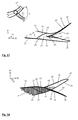
- the wing 3 shown in Fig. 10 differs from the embodiment shown in Fig. 1 to 9 in that the rear blade tip section 51, in particular at the rear blade leading edge 29 and at the rear blade trailing edge 31, from the base section 47 to the rear blade tip 37 after a curved developing has a straight developing which is not curved anymore.
- the transition of the curved developing to the straight developing is tangent-continuous, i.e. without any kinks or discontinuities.
- a third embodiment of a wing 3 according to the invention is illustrated which is similar to the embodiment described in connection with Figs. 1 to 9 , so that corresponding reference numerals are used for similar features.
- the wing 3 shown in Fig. 11 differs from the embodiment shown in Fig. 1 to 9 in that the front blade 21 extends upwards out of the wing plane 43 and the rear blade 27 extends downwards out of the wing plane 43, with reference to the wing thickness direction 41.
- a fourth embodiment of a wing 3 according to the invention is illustrated which is similar to the embodiment described in connection with Figs. 1 to 9 , so that corresponding reference numerals are used for similar features.
- the wing 3 shown in Fig. 12 differs from the embodiment shown in Fig. 1 to 9 in that the front blade 21 extends approximately flat in the wing plane 43 and the rear blade 27 extends upwards out of the wing plane 43, with reference to the wing thickness direction 41.
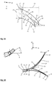
- a fifth embodiment of a wing 3 according to the invention is illustrated which is similar to the embodiment described in connection with Figs. 1 to 9 , so that corresponding reference numerals are used for similar features.
- the wing 3 shown in Figs. 13 to 18 differs from the embodiment shown in Fig. 1 to 9 in that the front blade trailing edge 25 intersects the rear blade leading edge 29, when viewed in the wing thickness direction 41, so that near the attachment end 19 the front blade trailing edge 25 extends behind the rear blade leading edge 29, and remote from the attachment end 19 the front blade trailing edge 25 extends in front of the rear blade leading edge 29, when viewed in the chord direction 33.
- the geometry of the wing 3, in particular the geometry of the wing tip device 9, is further specified in the following.
- the sweep angle ⁇ in general represents the angle with respect to the pitch axis p of the associated aircraft 1 in a plane spanned by the roll axis r and the pitch axis.
- a sweep angle ⁇ which is measured at the front or rear blade tips 35, 37 is measured right before the beginning of the tip caps 39, i.e. at the connection line 59 to the tip caps 39.
- a sweep angle ⁇ 7 of the front blade leading edge 23, when measured at the front blade tip 35, corresponds to an angle between the sweep angle ⁇ 2 of the wing leading edge 11 and twice the sweep angle ⁇ 2 of the wing leading edge 11, when measured at the wing tip end 17, and in the present embodiment is approximately 65°.
- a sweep angle ⁇ 10 of the rear blade trailing edge 31, when measured at the rear blade tip 37, corresponds to an angle between the sweep angle ⁇ 4 of the wing trailing edge 13 and twice the sweep angle ⁇ 4 of the wing trailing edge 13, when measured at the wing tip end 17, and in the present embodiment is approximately 52°.
- a chord extent c of the wing tip device 9 is addressed.
- the extent c1 of the front blade 21 in the chord direction 33, when measured at the front blade root 53, is approximately 60% of the extent c2 of the wing tip device 9 in the chord direction 33, when measured at the attachment end 19.
- the extent c3 of the front blade 21 in the chord direction 33, when measured at the front blade tip 35, is approximately 25% of the extent c2 of the wing tip device 9 in the chord direction 33, when measured at the attachment end 19.
- the extent c4 of the rear blade 27 in the chord direction 33, when measured at the rear blade root 55, is approximately 50% of the extent c2 of the wing tip device 9 in the chord direction 33, when measured at the attachment end 19.
- the extent c5 of the rear blade 27 in the chord direction 33, when measured at the rear blade tip 37, is approximately 25% of the extent c2 of the wing tip device 9 in the chord direction 33, when measured at the attachment end 19.
- a span extent s of the wing tip device 9 is addressed.
- the extent s1 of the front blade 21 in a span direction 61, when measured between the attachment end 19 and the front blade tip 35, is approximately 170% of the extent c2 of the wing tip device 9 in the chord direction 33, when measured at the attachment end 19.
- the extent s2 of the rear blade 27 in a span direction 61, when measured between the attachment end 19 and the rear blade tip 37, is approximately 160% of the extent c2 of the wing tip device 9 in the chord direction 33, when measured at the attachment end 19.
- an overlap extent o of the wing tip device 9 is addressed.
- the extent o of the overlapping area 45, when measured along the junction line 57, is approximately 30% of the extent c2 of the wing tip device 9 in the chord direction 33, when measured at the attachment end 19.
- a dihedral angle ⁇ of the wing tip device 9 is addressed.
- the dihedral angle ⁇ is measured with reference to a pitch axis p of the associated aircraft 1 in a plane spanned by the pitch axis p and the yaw axis y.
- the dihedral angle ⁇ 1 of the front blade leading edge 23, when measured at the attachment end 19, corresponds to the dihedral angle ⁇ 2 of the wing leading edge 11, when measured at the wing tip end 17.
- the dihedral angle ⁇ 3 of the rear blade trailing edge 31, when measured at the attachment end 19, corresponds to the dihedral angle ⁇ 4 of the wing trailing edge 13, when measured at the wing tip end 17.
- the dihedral angle ⁇ 5 of the front blade 21, when measured at the front blade tip 35, in the present embodiment is approximately 55°.
- the dihedral angle ⁇ 6 of the rear blade 27, when measured at the rear blade tip 37, in the present embodiment is approximately 35°.
- a junction angle ⁇ of the wing tip device 9 is addressed.
- the junction angle ⁇ is measured between the front blade 21 and the rear blade 27 along the junction line 57 in a plane spanned by the pitch axis p and the yaw axis y.
- the junction angle ⁇ 1 when measured at the rear blade leading edge 29, in the present embodiment is approximately 15°.
- the junction angle ⁇ 2, when measured at the front blade trailing edge 25, in the present embodiment is approximately 45°.
Landscapes
- Engineering & Computer Science (AREA)
- Aviation & Aerospace Engineering (AREA)
- Structures Of Non-Positive Displacement Pumps (AREA)
- Turbine Rotor Nozzle Sealing (AREA)
Priority Applications (5)
| Application Number | Priority Date | Filing Date | Title |
|---|---|---|---|
| EP14185039.6A EP2998218A1 (fr) | 2014-09-16 | 2014-09-16 | Aile d'un aéronef et aéronef comportant une telle aile |
| EP15754234.1A EP3194262B1 (fr) | 2014-09-16 | 2015-08-26 | Aile d'un aéronef et aéronef comportant une telle aile |
| CN201580050077.2A CN107074350B (zh) | 2014-09-16 | 2015-08-26 | 一种用于飞行器的机翼以及包括这种机翼的飞行器 |
| PCT/EP2015/069573 WO2016041751A1 (fr) | 2014-09-16 | 2015-08-26 | Aile pour aéronef, et aéronef comprenant une telle aile |
| US15/460,107 US9988142B2 (en) | 2014-09-16 | 2017-03-15 | Wing for an aircraft, and an aircraft comprising such a wing |
Applications Claiming Priority (1)
| Application Number | Priority Date | Filing Date | Title |
|---|---|---|---|
| EP14185039.6A EP2998218A1 (fr) | 2014-09-16 | 2014-09-16 | Aile d'un aéronef et aéronef comportant une telle aile |
Publications (1)
| Publication Number | Publication Date |
|---|---|
| EP2998218A1 true EP2998218A1 (fr) | 2016-03-23 |
Family
ID=51570298
Family Applications (2)
| Application Number | Title | Priority Date | Filing Date |
|---|---|---|---|
| EP14185039.6A Withdrawn EP2998218A1 (fr) | 2014-09-16 | 2014-09-16 | Aile d'un aéronef et aéronef comportant une telle aile |
| EP15754234.1A Active EP3194262B1 (fr) | 2014-09-16 | 2015-08-26 | Aile d'un aéronef et aéronef comportant une telle aile |
Family Applications After (1)
| Application Number | Title | Priority Date | Filing Date |
|---|---|---|---|
| EP15754234.1A Active EP3194262B1 (fr) | 2014-09-16 | 2015-08-26 | Aile d'un aéronef et aéronef comportant une telle aile |
Country Status (4)
| Country | Link |
|---|---|
| US (1) | US9988142B2 (fr) |
| EP (2) | EP2998218A1 (fr) |
| CN (1) | CN107074350B (fr) |
| WO (1) | WO2016041751A1 (fr) |
Cited By (5)
| Publication number | Priority date | Publication date | Assignee | Title |
|---|---|---|---|---|
| WO2019011395A1 (fr) * | 2017-07-12 | 2019-01-17 | The Aircraft Performance Company Gmbh | Aile d'avion pourvue d'au moins deux ailettes marginales |
| EP3511243A1 (fr) * | 2018-01-15 | 2019-07-17 | APC - The Aircraft Performance Company | Aile d'avion |
| US20210197961A1 (en) * | 2019-12-30 | 2021-07-01 | Bombardier Inc. | Winglet systems for aircraft |
| US11279469B2 (en) | 2016-07-12 | 2022-03-22 | The Aircraft Performance Company Gmbh | Airplane wing |
| US11396368B2 (en) | 2017-12-15 | 2022-07-26 | The Aircraft Performance Company Gmbh | Airplane wing |
Families Citing this family (20)
| Publication number | Priority date | Publication date | Assignee | Title |
|---|---|---|---|---|
| US9302766B2 (en) * | 2008-06-20 | 2016-04-05 | Aviation Partners, Inc. | Split blended winglet |
| DK2303685T3 (en) | 2008-06-20 | 2016-01-18 | Aviat Partners Inc | KRUM wingtip |
| CN103717490B (zh) * | 2011-06-09 | 2016-08-17 | 航空伙伴股份有限公司 | 螺旋形机翼末梢以及飞行器 |
| DE102011107251A1 (de) * | 2011-07-14 | 2013-01-17 | Airbus Operations Gmbh | Flügelendstück eines Tragflügels sowie ein Tragflügel mit einem solchen Flügelendstück |
| US10625847B2 (en) * | 2017-04-21 | 2020-04-21 | Textron Innovations Inc. | Split winglet |
| EP3486162B1 (fr) * | 2017-11-17 | 2020-07-01 | Airbus Operations GmbH | Procédé pour faire fonctionner une aile d'aéronef comprenant une partie d'extrémité d'aile pliable |
| US11034436B2 (en) * | 2018-07-12 | 2021-06-15 | General Electric Company | Aerodynamic tip feature |
| CN109250070B (zh) * | 2018-09-25 | 2021-09-14 | 陕西飞机工业(集团)有限公司 | 一种上单翼飞机襟翼放下角度标记方法 |
| AU2019201502B2 (en) * | 2018-11-16 | 2020-03-19 | Carolyn Burton | Hazard warning apparatus, system and method |
| WO2020146399A1 (fr) * | 2019-01-07 | 2020-07-16 | Aviation Partners, Inc. | Ailette marginale haute performance |
| USD930549S1 (en) | 2019-12-30 | 2021-09-14 | Bombardier Inc. | Aircraft winglet |
| USD978057S1 (en) | 2020-12-23 | 2023-02-14 | Bombardier Inc. | Aircraft winglet |
| GB2616252A (en) * | 2022-01-31 | 2023-09-06 | Airbus Operations Ltd | Aircraft with movable wing tip device |
| GB2615311A (en) * | 2022-01-31 | 2023-08-09 | Airbus Operations Ltd | Aircraft wing with movable wing tip device |
| CN114701662B (zh) * | 2022-06-07 | 2022-08-23 | 中国商用飞机有限责任公司 | 一种用于高升力系统倾斜探测的方法和装置 |
| US12434818B2 (en) * | 2022-06-17 | 2025-10-07 | Textron Innovations Inc. | Tandem split divergent winglet |
| GB2628523B (en) * | 2022-11-16 | 2025-07-09 | Airbus Operations Ltd | Aircraft wing |
| GB2630990B (en) * | 2023-06-16 | 2026-01-28 | Airbus Operations Ltd | An aircraft wing with a moveable wing tip |
| US12428138B2 (en) | 2023-09-08 | 2025-09-30 | Textron Innovations Inc. | Blended falx winglet |
| USD1073579S1 (en) * | 2023-09-08 | 2025-05-06 | Textron Innovations, Inc. | Blended falx winglet |
Citations (8)
| Publication number | Priority date | Publication date | Assignee | Title |
|---|---|---|---|---|
| US4674709A (en) * | 1983-06-20 | 1987-06-23 | Welles Stanley W | Airframe design |
| US20020162917A1 (en) | 2001-04-09 | 2002-11-07 | Fairchild Dornier Gmbh | Wing tip extension for a wing |
| US20090039204A1 (en) * | 2007-08-09 | 2009-02-12 | The Boeing Company | Wingtip Feathers, Including Forward Swept Feathers, and Associated Aircraft Systems and Methods |
| US20090084904A1 (en) | 2007-10-02 | 2009-04-02 | The Boeing Company | Wingtip Feathers, Including Paired, Fixed Feathers, and Associated Systems and Methods |
| US20100019094A1 (en) | 2006-11-21 | 2010-01-28 | Airbus Deutschland Gmbh | Wing tip shape for a wing, in particular of aircraft |
| US20120312928A1 (en) | 2011-06-09 | 2012-12-13 | Gratzer Louis B | Split Blended Winglet |
| US20130092797A1 (en) | 2010-07-14 | 2013-04-18 | Airbus Operations Gmbh | Wing tip device |
| US20130256460A1 (en) | 2012-03-30 | 2013-10-03 | The Boeing Company | Performance-enhancing winglet system and method |
Family Cites Families (14)
| Publication number | Priority date | Publication date | Assignee | Title |
|---|---|---|---|---|
| DE3242584A1 (de) * | 1982-11-18 | 1984-05-24 | Messerschmitt-Bölkow-Blohm GmbH, 8000 München | Anordnung von zusatzflaechen an den spitzen eines tragfluegels |
| US4545552A (en) * | 1983-06-20 | 1985-10-08 | Welles Stanley W | Airframe design |
| US5102068A (en) * | 1991-02-25 | 1992-04-07 | Gratzer Louis B | Spiroid-tipped wing |
| DE10302514B4 (de) * | 2003-01-23 | 2008-12-18 | Eads Deutschland Gmbh | Strömungsmechanisch wirksame Fläche eines sich in einem Fluid bewegenden Geräts, insbesondere eines Fluggeräts, insbesondere Tragfläche eines Fluggeräts |
| FR2901538B1 (fr) * | 2006-05-23 | 2008-07-18 | Airbus France Sas | Aeronef comportant un dispositif de reduction de la trainee induite |
| EP2064116B1 (fr) * | 2006-09-15 | 2014-07-23 | Airbus Operations GmbH | Corps aérodynamique et aile portante présentant un corps aérodynamique d'influence de post-turbulences |
| GB0711942D0 (en) * | 2007-06-21 | 2007-08-01 | Airbus Uk Ltd | Winglet |
| US9302766B2 (en) * | 2008-06-20 | 2016-04-05 | Aviation Partners, Inc. | Split blended winglet |
| CN101596934B (zh) * | 2009-07-02 | 2011-08-17 | 北京航空航天大学 | 一种翼梢涡扩散装置 |
| US8439313B2 (en) * | 2010-10-15 | 2013-05-14 | The Boeing Company | Forward swept winglet |
| US9452825B2 (en) * | 2013-04-19 | 2016-09-27 | The Boeing Company | Winglet attach fitting for attaching a split winglet to a wing |
| US9527581B2 (en) * | 2013-07-25 | 2016-12-27 | Joby Aviation, Inc. | Aerodynamically efficient lightweight vertical take-off and landing aircraft with multi-configuration wing tip mounted rotors |
| US9738375B2 (en) * | 2013-12-05 | 2017-08-22 | The Boeing Company | One-piece composite bifurcated winglet |
| GB2533413A (en) * | 2014-12-19 | 2016-06-22 | Airbus Operations Ltd | Lifting Surfaces |
-
2014
- 2014-09-16 EP EP14185039.6A patent/EP2998218A1/fr not_active Withdrawn
-
2015
- 2015-08-26 EP EP15754234.1A patent/EP3194262B1/fr active Active
- 2015-08-26 WO PCT/EP2015/069573 patent/WO2016041751A1/fr not_active Ceased
- 2015-08-26 CN CN201580050077.2A patent/CN107074350B/zh active Active
-
2017
- 2017-03-15 US US15/460,107 patent/US9988142B2/en active Active
Patent Citations (8)
| Publication number | Priority date | Publication date | Assignee | Title |
|---|---|---|---|---|
| US4674709A (en) * | 1983-06-20 | 1987-06-23 | Welles Stanley W | Airframe design |
| US20020162917A1 (en) | 2001-04-09 | 2002-11-07 | Fairchild Dornier Gmbh | Wing tip extension for a wing |
| US20100019094A1 (en) | 2006-11-21 | 2010-01-28 | Airbus Deutschland Gmbh | Wing tip shape for a wing, in particular of aircraft |
| US20090039204A1 (en) * | 2007-08-09 | 2009-02-12 | The Boeing Company | Wingtip Feathers, Including Forward Swept Feathers, and Associated Aircraft Systems and Methods |
| US20090084904A1 (en) | 2007-10-02 | 2009-04-02 | The Boeing Company | Wingtip Feathers, Including Paired, Fixed Feathers, and Associated Systems and Methods |
| US20130092797A1 (en) | 2010-07-14 | 2013-04-18 | Airbus Operations Gmbh | Wing tip device |
| US20120312928A1 (en) | 2011-06-09 | 2012-12-13 | Gratzer Louis B | Split Blended Winglet |
| US20130256460A1 (en) | 2012-03-30 | 2013-10-03 | The Boeing Company | Performance-enhancing winglet system and method |
Non-Patent Citations (1)
| Title |
|---|
| G. LOEBERT: "Der Flugel mit Gabelspitzen als Mittel zur Erhohung der Wirtschaftlichkeit von Transportflugzeugen", MBB-UFE 1344, 1977 |
Cited By (11)
| Publication number | Priority date | Publication date | Assignee | Title |
|---|---|---|---|---|
| US11279469B2 (en) | 2016-07-12 | 2022-03-22 | The Aircraft Performance Company Gmbh | Airplane wing |
| WO2019011395A1 (fr) * | 2017-07-12 | 2019-01-17 | The Aircraft Performance Company Gmbh | Aile d'avion pourvue d'au moins deux ailettes marginales |
| CN110891857A (zh) * | 2017-07-12 | 2020-03-17 | 航空器性能公司 | 具有至少两个小翼的飞机机翼 |
| US11312481B2 (en) | 2017-07-12 | 2022-04-26 | The Aircraft Performance Company Gmbh | Airplane wing |
| US11396368B2 (en) | 2017-12-15 | 2022-07-26 | The Aircraft Performance Company Gmbh | Airplane wing |
| EP3511243A1 (fr) * | 2018-01-15 | 2019-07-17 | APC - The Aircraft Performance Company | Aile d'avion |
| WO2019138100A1 (fr) * | 2018-01-15 | 2019-07-18 | The Aircraft Performance Company Gmbh | Aile d'avion |
| US11427307B2 (en) | 2018-01-15 | 2022-08-30 | The Aircraft Performance Company Gmbh | Airplane wing |
| US20210197961A1 (en) * | 2019-12-30 | 2021-07-01 | Bombardier Inc. | Winglet systems for aircraft |
| EP3845451A1 (fr) * | 2019-12-30 | 2021-07-07 | Bombardier Inc. | Systèmes d'ailette pour aéronef |
| EP4223633A1 (fr) * | 2019-12-30 | 2023-08-09 | Bombardier Inc. | Systèmes d'ailette pour aéronef |
Also Published As
| Publication number | Publication date |
|---|---|
| EP3194262A1 (fr) | 2017-07-26 |
| WO2016041751A1 (fr) | 2016-03-24 |
| EP3194262B1 (fr) | 2018-07-25 |
| CN107074350B (zh) | 2019-07-05 |
| CN107074350A (zh) | 2017-08-18 |
| US9988142B2 (en) | 2018-06-05 |
| US20170247105A1 (en) | 2017-08-31 |
Similar Documents
| Publication | Publication Date | Title |
|---|---|---|
| EP3194262B1 (fr) | Aile d'un aéronef et aéronef comportant une telle aile | |
| US12515787B2 (en) | Wing tip device | |
| CN101965291B (zh) | 冲击突起阵列 | |
| CN104144853B (zh) | 机翼的翼尖装置和具有这种翼尖装置的机翼 | |
| CN107757879B (zh) | 用于飞行器的机翼的翼尖装置、飞行器及用途 | |
| US11673653B2 (en) | Wingtip device | |
| US11148788B2 (en) | Curved wingtip for aircraft | |
| US8651427B1 (en) | Wing tip device with recess in surface | |
| US20170073062A1 (en) | Variable Geometry Wingtip | |
| CN106184710B (zh) | 飞机机翼的翼尖装置 | |
| US20070262205A1 (en) | Retractable multiple winglet | |
| CN203740128U (zh) | 乘波体飞行器 | |
| US20230192274A1 (en) | Wingtip | |
| KR102669013B1 (ko) | 항공기 날개 및 윙팁 장치 | |
| CN202541831U (zh) | 一种飞机小翼 | |
| CN107021202B (zh) | 一种带棱边的飞机机头 | |
| CN109263855A (zh) | 一种采用后缘支撑翼的超大展弦比飞行器气动布局 | |
| RU2525335C1 (ru) | Законцовка крыла летательного аппарата | |
| DE102008039061B4 (de) | Trennvorrichtung zur Vermeidung der Kontamination der Grenzschicht auf gepfeilten Tragflächen eines Flugkörpers durch den Rumpf oder ähnliche Körper | |
| CN206797703U (zh) | 一种飞机翼梢小翼 | |
| CN204726675U (zh) | 一种尾吊发动机短舱吊挂 | |
| CN104176233B (zh) | 一种栗型机翼的形状 | |
| RU2349499C2 (ru) | Горизонтальное оперение самолета интегральной схемы | |
| CN101830280A (zh) | 一种飞行器气动布局 | |
| WO2019108090A1 (fr) | Surface aérodynamique multi-modes |
Legal Events
| Date | Code | Title | Description |
|---|---|---|---|
| PUAI | Public reference made under article 153(3) epc to a published international application that has entered the european phase |
Free format text: ORIGINAL CODE: 0009012 |
|
| AK | Designated contracting states |
Kind code of ref document: A1 Designated state(s): AL AT BE BG CH CY CZ DE DK EE ES FI FR GB GR HR HU IE IS IT LI LT LU LV MC MK MT NL NO PL PT RO RS SE SI SK SM TR |
|
| AX | Request for extension of the european patent |
Extension state: BA ME |
|
| STAA | Information on the status of an ep patent application or granted ep patent |
Free format text: STATUS: THE APPLICATION IS DEEMED TO BE WITHDRAWN |
|
| 18D | Application deemed to be withdrawn |
Effective date: 20160924 |