EP2998483A1 - Bouton rotatif destiné à actionner un adaptateur de cylindre d'un barillet - Google Patents
Bouton rotatif destiné à actionner un adaptateur de cylindre d'un barillet Download PDFInfo
- Publication number
- EP2998483A1 EP2998483A1 EP14185852.2A EP14185852A EP2998483A1 EP 2998483 A1 EP2998483 A1 EP 2998483A1 EP 14185852 A EP14185852 A EP 14185852A EP 2998483 A1 EP2998483 A1 EP 2998483A1
- Authority
- EP
- European Patent Office
- Prior art keywords
- drive
- holder
- rotary knob
- knob
- battery
- Prior art date
- Legal status (The legal status is an assumption and is not a legal conclusion. Google has not performed a legal analysis and makes no representation as to the accuracy of the status listed.)
- Withdrawn
Links
- 230000008878 coupling Effects 0.000 claims abstract description 120
- 238000010168 coupling process Methods 0.000 claims abstract description 120
- 238000005859 coupling reaction Methods 0.000 claims abstract description 120
- 238000003780 insertion Methods 0.000 claims description 13
- 230000037431 insertion Effects 0.000 claims description 13
- 230000000295 complement effect Effects 0.000 claims description 5
- 210000001331 nose Anatomy 0.000 description 11
- 230000013011 mating Effects 0.000 description 10
- 230000002093 peripheral effect Effects 0.000 description 9
- 230000004888 barrier function Effects 0.000 description 4
- 238000000034 method Methods 0.000 description 4
- 238000013475 authorization Methods 0.000 description 3
- 230000008901 benefit Effects 0.000 description 3
- 238000006073 displacement reaction Methods 0.000 description 3
- 230000007246 mechanism Effects 0.000 description 3
- 230000005540 biological transmission Effects 0.000 description 2
- 238000010276 construction Methods 0.000 description 2
- 238000013461 design Methods 0.000 description 2
- 238000009434 installation Methods 0.000 description 2
- WHXSMMKQMYFTQS-UHFFFAOYSA-N Lithium Chemical compound [Li] WHXSMMKQMYFTQS-UHFFFAOYSA-N 0.000 description 1
- 238000005253 cladding Methods 0.000 description 1
- 238000004891 communication Methods 0.000 description 1
- 230000001419 dependent effect Effects 0.000 description 1
- 238000011161 development Methods 0.000 description 1
- 230000018109 developmental process Effects 0.000 description 1
- 230000000694 effects Effects 0.000 description 1
- 210000003746 feather Anatomy 0.000 description 1
- 210000003128 head Anatomy 0.000 description 1
- 239000002655 kraft paper Substances 0.000 description 1
- 229910052744 lithium Inorganic materials 0.000 description 1
- 238000004519 manufacturing process Methods 0.000 description 1
- 239000000463 material Substances 0.000 description 1
- 229910052751 metal Inorganic materials 0.000 description 1
- 239000002184 metal Substances 0.000 description 1
- 229910001172 neodymium magnet Inorganic materials 0.000 description 1
- 239000012811 non-conductive material Substances 0.000 description 1
- 239000002245 particle Substances 0.000 description 1
- BASFCYQUMIYNBI-UHFFFAOYSA-N platinum Chemical compound [Pt] BASFCYQUMIYNBI-UHFFFAOYSA-N 0.000 description 1
- 229920000642 polymer Polymers 0.000 description 1
- 230000001105 regulatory effect Effects 0.000 description 1
- 125000006850 spacer group Chemical group 0.000 description 1
- 238000003860 storage Methods 0.000 description 1
- 230000007704 transition Effects 0.000 description 1
Images







Classifications
-
- E—FIXED CONSTRUCTIONS
- E05—LOCKS; KEYS; WINDOW OR DOOR FITTINGS; SAFES
- E05B—LOCKS; ACCESSORIES THEREFOR; HANDCUFFS
- E05B47/00—Operating or controlling locks or other fastening devices by electric or magnetic means
- E05B47/06—Controlling mechanically-operated bolts by electro-magnetically-operated detents
- E05B47/0611—Cylinder locks with electromagnetic control
- E05B47/0615—Cylinder locks with electromagnetic control operated by handles, e.g. by knobs
-
- E—FIXED CONSTRUCTIONS
- E05—LOCKS; KEYS; WINDOW OR DOOR FITTINGS; SAFES
- E05B—LOCKS; ACCESSORIES THEREFOR; HANDCUFFS
- E05B47/00—Operating or controlling locks or other fastening devices by electric or magnetic means
- E05B47/06—Controlling mechanically-operated bolts by electro-magnetically-operated detents
- E05B47/0611—Cylinder locks with electromagnetic control
- E05B47/0638—Cylinder locks with electromagnetic control by disconnecting the rotor
- E05B47/0642—Cylinder locks with electromagnetic control by disconnecting the rotor axially, i.e. with an axially disengaging coupling element
-
- E—FIXED CONSTRUCTIONS
- E05—LOCKS; KEYS; WINDOW OR DOOR FITTINGS; SAFES
- E05B—LOCKS; ACCESSORIES THEREFOR; HANDCUFFS
- E05B47/00—Operating or controlling locks or other fastening devices by electric or magnetic means
- E05B47/06—Controlling mechanically-operated bolts by electro-magnetically-operated detents
- E05B47/0676—Controlling mechanically-operated bolts by electro-magnetically-operated detents by disconnecting the handle
- E05B47/068—Controlling mechanically-operated bolts by electro-magnetically-operated detents by disconnecting the handle axially, i.e. with an axially disengaging coupling element
-
- E—FIXED CONSTRUCTIONS
- E05—LOCKS; KEYS; WINDOW OR DOOR FITTINGS; SAFES
- E05B—LOCKS; ACCESSORIES THEREFOR; HANDCUFFS
- E05B1/00—Knobs or handles for wings; Knobs, handles, or press buttons for locks or latches on wings
- E05B1/0084—Handles or knobs with displays, signs, labels pictures, or the like
-
- E—FIXED CONSTRUCTIONS
- E05—LOCKS; KEYS; WINDOW OR DOOR FITTINGS; SAFES
- E05B—LOCKS; ACCESSORIES THEREFOR; HANDCUFFS
- E05B15/00—Other details of locks; Parts for engagement by bolts of fastening devices
- E05B15/0053—Other details of locks; Parts for engagement by bolts of fastening devices means providing a stable, i.e. indexed, position of lock parts
- E05B15/0073—Other details of locks; Parts for engagement by bolts of fastening devices means providing a stable, i.e. indexed, position of lock parts magnetically operated
-
- E—FIXED CONSTRUCTIONS
- E05—LOCKS; KEYS; WINDOW OR DOOR FITTINGS; SAFES
- E05B—LOCKS; ACCESSORIES THEREFOR; HANDCUFFS
- E05B9/00—Lock casings or latch-mechanism casings ; Fastening locks or fasteners or parts thereof to the wing
- E05B9/04—Casings of cylinder locks
- E05B2009/046—Cylinder locks operated by knobs or handles
-
- E—FIXED CONSTRUCTIONS
- E05—LOCKS; KEYS; WINDOW OR DOOR FITTINGS; SAFES
- E05B—LOCKS; ACCESSORIES THEREFOR; HANDCUFFS
- E05B47/00—Operating or controlling locks or other fastening devices by electric or magnetic means
- E05B47/0001—Operating or controlling locks or other fastening devices by electric or magnetic means with electric actuators; Constructional features thereof
- E05B2047/0014—Constructional features of actuators or power transmissions therefor
- E05B2047/0015—Output elements of actuators
- E05B2047/0016—Output elements of actuators with linearly reciprocating motion
-
- E—FIXED CONSTRUCTIONS
- E05—LOCKS; KEYS; WINDOW OR DOOR FITTINGS; SAFES
- E05B—LOCKS; ACCESSORIES THEREFOR; HANDCUFFS
- E05B47/00—Operating or controlling locks or other fastening devices by electric or magnetic means
- E05B2047/0048—Circuits, feeding, monitoring
- E05B2047/0057—Feeding
- E05B2047/0058—Feeding by batteries
-
- E—FIXED CONSTRUCTIONS
- E05—LOCKS; KEYS; WINDOW OR DOOR FITTINGS; SAFES
- E05B—LOCKS; ACCESSORIES THEREFOR; HANDCUFFS
- E05B47/00—Operating or controlling locks or other fastening devices by electric or magnetic means
- E05B2047/0048—Circuits, feeding, monitoring
- E05B2047/0067—Monitoring
-
- E—FIXED CONSTRUCTIONS
- E05—LOCKS; KEYS; WINDOW OR DOOR FITTINGS; SAFES
- E05B—LOCKS; ACCESSORIES THEREFOR; HANDCUFFS
- E05B47/00—Operating or controlling locks or other fastening devices by electric or magnetic means
- E05B47/0001—Operating or controlling locks or other fastening devices by electric or magnetic means with electric actuators; Constructional features thereof
- E05B47/0012—Operating or controlling locks or other fastening devices by electric or magnetic means with electric actuators; Constructional features thereof with rotary electromotors
-
- E—FIXED CONSTRUCTIONS
- E05—LOCKS; KEYS; WINDOW OR DOOR FITTINGS; SAFES
- E05B—LOCKS; ACCESSORIES THEREFOR; HANDCUFFS
- E05B47/00—Operating or controlling locks or other fastening devices by electric or magnetic means
- E05B47/0038—Operating or controlling locks or other fastening devices by electric or magnetic means using permanent magnets
-
- E—FIXED CONSTRUCTIONS
- E05—LOCKS; KEYS; WINDOW OR DOOR FITTINGS; SAFES
- E05B—LOCKS; ACCESSORIES THEREFOR; HANDCUFFS
- E05B63/00—Locks or fastenings with special structural characteristics
- E05B63/0056—Locks with adjustable or exchangeable lock parts
- E05B63/006—Locks with adjustable or exchangeable lock parts for different door thicknesses
-
- G—PHYSICS
- G07—CHECKING-DEVICES
- G07C—TIME OR ATTENDANCE REGISTERS; REGISTERING OR INDICATING THE WORKING OF MACHINES; GENERATING RANDOM NUMBERS; VOTING OR LOTTERY APPARATUS; ARRANGEMENTS, SYSTEMS OR APPARATUS FOR CHECKING NOT PROVIDED FOR ELSEWHERE
- G07C9/00—Individual registration on entry or exit
- G07C9/00174—Electronically operated locks; Circuits therefor; Nonmechanical keys therefor, e.g. passive or active electrical keys or other data carriers without mechanical keys
Definitions
- Such rotary knobs are well known.
- mechatronic rotary knobs are known, by which a cylinder adapter of a lock cylinder can be unlocked from a door page only after previous authentication.
- the authentication can be done for example by means of a chip or an ID card.
- the knob is decoupled from the cylinder adapter. Therefore, turning the knob does not result in rotation of a closing member of the cylinder adapter, and thus the door can not be opened.
- a coupling slide is brought into positive engagement with a coupling element via a drive, which may be, for example, a motor, so that a torque applied to the rotary knob via the coupling slide and the positively connected Coupling element is transmitted to the closing element of the cylinder adapter.
- a drive which may be, for example, a motor
- the drive is arranged directly in a holder in the knob.
- this has the disadvantage of a complicated and complex assembly due to tight space conditions.
- the drive can also be difficult to replace be, if at all possible, without having to destroy the knob.
- the bracket and thus also the rotary knob must be adapted to the size of the drive in different applications. This can lead to increased costs and a large number of knobs, which must be kept as a stick.
- the assembly or disassembly of the rotary knob can be simplified.
- the drive can be used outside of the knob in the drive pocket and thus the drive and the drive pocket can serve as a preassembled module, which is then used in a simple manner in the knob.
- it can be ensured that the drive is inserted with the correct orientation into the first holder.
- potential assembly errors can be eliminated.
- a fitter can insert the drive pocket with the drive approximately like a drawer into the first holder of the base body.
- the drive pocket serves as a storage for the drive, whereby the forces resulting from the drive are not transmitted directly to the body. This creates a pleasant for the user Operating feeling of the knob.
- the drive in the drive pocket is protected from dirt or particles.
- a cable of the drive can also be securely arranged in the drive pocket.
- the drive pocket serves as an additional hurdle for potential burglars, making manipulation of the drive difficult or can be prevented.
- the base body may be at least partially hollow cylindrical and have a lateral surface, wherein the first holder is disposed on an inner side of the lateral surface. Due to the shape of the base body, the arrangement of the first holder can be provided in the rotary knob.
- the base body has a longitudinal axis, in particular a central axis, wherein the first holder is formed with the largest possible distance from the longitudinal axis.
- the coupling slide and the coupling element are made compact and lightweight.
- the coupling slide can be accelerated quickly, whereby short coupling and decoupling times can be realized.
- a user can quickly unlock the lock cylinder and open the door.
- the coupling slider can quickly return to its decoupled state in which access is prevented without new authentication.
- the drive pocket can have a shape substantially complementary to a shape of the first holder, wherein in particular the first holder is rotationally asymmetrical. Due to the mutually complementary shapes of the first holder and the drive pocket is a stable arrangement of the drive pocket in the first Holder allows. Furthermore, the forces generated by the engine can be transmitted via the drive pocket substantially uniformly to the first holder.
- the drive pocket can be formed rotationally asymmetrical, whereby the orientation of the drive pocket in the first holder is predetermined in the insertion direction.
- the drive pocket may preferably have an L-shaped cross section.
- the rotary knob may further comprise a second holder, in which the coupling slide can be inserted simultaneously with the drive pocket, wherein in particular the second holder is provided on the inside of the lateral surface.
- the second bracket carries at least a portion of the weight of the coupling slide, which is connected to the drive shaft of the drive, in the decoupled state. This can be avoided that the motor shaft is loaded with the full weight of the coupling slide.
- the coupling slide can be mounted in the second holder, whereby the forces exerted on the coupling slide via a coupling element counter forces are absorbed in the coupled state of the coupling slide.
- the insertability of the coupling slide offers the advantage of easy installation.
- the assembly steps are reduced and, accordingly, the assembly time is shortened.
- the drive can be pre-assembled with the coupling slide outside the main body of the knob, which facilitates the entire assembly of the knob.
- the arrangement of the second holder on the inside of the lateral surface of the base body allows a compact and lightweight construction of the various components.
- the second holder can preferably be arranged in the radial direction farther away from a longitudinal axis, in particular a central axis, of the main body than the first holder.
- the second holder may preferably be arranged directly on the inside of the lateral surface of the base body.
- the coupling slide advantageously at least partially has a shape substantially complementary to a shape of the second holder.
- the coupling slide in the second holder is displaceable in the direction of a longitudinal axis of the main body.
- the second holder can serve as a guide for the coupling slide, wherein the coupling slide between a decoupled state and a coupled state is slidably disposed.
- the rotary knob may have a threaded spindle, which can convert a rotational movement of the drive into a linear movement of the coupling slide.
- the threaded spindle can be glued to a shaft of the drive.
- the threaded spindle can be positively connected by means of a connecting element with the coupling slide.
- the connecting element may preferably be formed as a driver, which is rotatably connected to the threaded spindle, and causes the movement of the coupling slide when the drive drives the threaded spindle.
- the driver may be screwed onto the threaded spindle.
- the coupling slide may preferably have a coupling slide recess, in which the driver is arranged.
- the driver may have a first disk-shaped region, which has a shape substantially complementary to a shape of the coupling slide recess.
- the driver can be arranged with play in the coupling slide recess to compensate for misalignment between the coupling slide and the driver.
- the drive pocket may have a drive connector holder in which a drive connector, in particular with play, is arranged in order to provide electrical contact between the drive and at least one electrical component of the rotary knob.
- a drive connector in particular with play
- the drive connector By the drive connector, a simple electrical contacting of the drive can be provided with electrical components of the body.
- the intended clearance compensates for potential misalignment between the drive connector and the at least one electrical component. It may also be advantageous if the drive connector is designed such that the drive connector can be used only in one orientation in the drive connector holder.
- a drive mating connector on a circuit board in particular a first board part, be arranged, wherein the drive mating connector cooperates with the drive connector.
- the board can be electrically contacted with the drive in a simple manner.
- the first board part in relation to the cylinder adapter in front of the drive, wherein in particular the first board part is partially disposed under the coupling slide.
- the first board part serves as manipulation protection for the drive and simplifies the electrical contact with the drive. Furthermore, a compact structure can be made possible.
- the first board part may have a recess through which the coupling slide at least partially movable and / or in which the second holder is at least partially disposed, wherein in particular the first board part is radially fixed.
- the drive pocket may have a cable channel in which a cable for electrically contacting the drive with the drive connector extends.
- the cable is arranged protected in the cable channel.
- the drive pocket may have a drive pocket stop which limits the insertion of the drive pocket into the first holder.
- a movement of the drive pocket is prevented in the insertion direction and determines their final position.
- the drive pocket has at least one clip nose over which the drive pocket can be latched to the holder.
- the drive pocket on two clip noses which are identical.
- the clip noses can have a resilient function.
- the first holder may be formed as a passage opening or a blind opening in the base body.
- a blind opening is an opening to understand that does not completely penetrate the body.
- the fact that the first holder is formed as an opening can be dispensed with an additional component, thereby manufacturing costs and installation costs can be saved.
- the passage opening allows unlocking of the drive pocket of the first holder, wherein in the case of a blind opening further manipulation protection for the drive is provided.
- a second board part is arranged behind the drive with respect to the cylinder adapter and covers the first holder, wherein in particular the main body has a shoulder, so that the second board part is mounted at a distance from the first holder.
- the Arrangement of the second board part serves to protect against manipulation of the drive.
- the present invention relates to a lock cylinder, which comprises a rotary knob according to the invention and a cylinder adapter which can be actuated by the rotary knob, wherein the drive pocket is inserted in the first holder.
- Fig. 1 schematically shows an exploded view of the lock cylinder 2 with all structural components. The combination of the individual structural components to the lock cylinder 2 according to the invention is described in the following figures.
- the lock cylinder 2 comprises three components: a rotary knob 1, a cylinder adapter 3 and an inner knob 4. Both via the knob 1 and via the inner knob 4 of the cylinder adapter 3 can be actuated, so that in particular a equipped with the lock cylinder 2 door is releasable. It is inventively provided that the cylinder adapter 3 is always controlled via the inner knob 4, while the knob 1 can be decoupled from a coupling unit 65 of the cylinder adapter 3, so that the knob 1 is freely rotatable.
- the structure of the dome unit 65 is in Fig. 2 shown.
- Fig. 2 shows an exploded view of the dome unit 65.
- the dome unit 65 includes a drive pocket 14, in which a drive 15 is received.
- the drive 15 is connected to a threaded spindle 17, so that the threaded spindle 17 is rotatable by the drive 15.
- a driver 18 is arranged so that by a rotation of the threaded spindle 17 by the drive 15 of the driver 18 is axially displaced on the threaded spindle 17 when the driver 18 is held against rotation.
- For rotationally fixed holding the driver 18 is arranged in a first coupling slide recess 27 of a coupling slide 16.
- the coupling slide 16 is again, as in Fig.
- the coupling slide 16 is movable by the drive 15 by a rotation of the drive 15 causes a rotation of the threaded spindle 17, whereby the driver 18 is displaced on the threaded spindle 17, which is due to the arrangement of the driver 18 in the first coupling slide recess 27th affects the coupling slide 16.
- the coupling slide 16 is parallel to a shaft of the drive 15 and thus parallel to the threaded spindle 17 movable.
- the coupling slide 16 has an engagement element 29.
- the function of the engagement member 29 will be described with reference to FIG Fig. 9 described.
- the coupling slide 16 may advantageously have a second coupling slide recess 28, whereby the coupling slide 16 has a very low weight.
- the coupling slider 16 is easy and quick to accelerate, so short shift times are guaranteed.
- the drive 15 is arranged within the drive pocket 14. It is also provided that a cable for supplying the drive 15 with electrical energy in a cable channel (not shown) of the motor pocket 14 is guided.
- the cable of the drive 15 is threaded under the drive 15 or laterally of the drive pocket 14 and ends in a drive connector 19.
- the motor pocket 14 has a drive connector holder 26.
- the drive connector holder 26 of the drive connector 19 is arranged, in particular inserted from below, wherein the drive connector 19 is formed as a drive connector and connected to the cable.
- the drive 15 via the drive connector 19 is electrically contacted and thus controlled.
- the drive connector 19 is disposed with play within the drive connector holder 26 of the motor pocket 14. The electrical contacting of the drive connector 19 is in the Fig. 5 and 6 shown.
- Fig. 3 shows the drive 15 with the threaded spindle 17.
- the drive 15 is preferably a DC motor and advantageously has a diameter of 6 mm.
- the threaded spindle 17 is mounted on a shaft of the drive 15, wherein a distance 200 between a housing of the drive 15 and the threaded spindle 17 is advantageously 0.3 mm to 0.5 mm.
- the threaded spindle 17 is in particular an M2 threaded spindle.
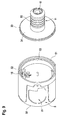
- the dome unit 65 can be inserted into the main body 5 of the rotary knob 1.
- the main body 5 which is preferably made of metal, has a first holder 21 and a second holder 22.
- the first holder 21 serves to receive the drive pocket 14, while the second holder 22 serves to receive the coupling slide 16.
- the drive pocket 14 also has a drive stop 25, which rests after insertion of the drive pocket 14 in the first holder 21 on the base body 5. It is also provided that in this position clip projections 24 of the drive pocket 14 surround the first holder 21, so that a positive connection between the first holder 21 of the base body 5 and the drive pocket 14 of the coupling unit 65 is present.
- the dome unit 65 is firmly and securely locked in the main body 5.
- the coupling slider 16 is disposed within the second bracket 22.
- the coupling slide 16 is longitudinally displaceable, d. H. parallel to a longitudinal axis 100 of the main body 5.
- the longitudinal axis 100 is arranged parallel to the shaft of the drive 15. Other movements of the coupling slide 16, in particular a rotation of the coupling slide 16, are prevented by the second holder 22.
- the main body 5 has in particular a diameter of 40 mm.
- the main body 5 is advantageously formed as a hollow cylinder, wherein the cylindrical base body 5 has a lateral surface 20.
- the second holder 22 is mounted, wherein the first holder 21 is disposed radially inwardly relative to the second holder 22.
- the main body 5 also has a battery recess 23, which is formed by a first jacket opening 54.
- the functionality of the battery recess 23 will be described with reference to FIG Fig. 13 explained.
- the first holder 21 and / or the second holder 22 may be formed as an axial passage opening of the main body 5.
- both the first holder 21 and the second holder 22 are not passage openings.
- the first holder 21 and the second holder 22 are axially accessible only from one side. From the axially opposite side, reaching the first holder 21 and / or the second holder 22 is thus not possible. It is provided in particular that this page is the side facing away from the cylinder adapter 3. Thus, a manipulation of the coupling unit 65 and thus of the rotary knob 1 can be prevented.
- the Fig. 5 and 6 show a board 10 which is disposed within the knob 1. It is provided that a first board part 57 of a first end face 51 of the base body 5 (see. Fig. 7 ) is attached to the base body 5, while a second board part 61 from a second end face 52 (see. Fig. 7 ) of the main body 5 is attached to the main body 5. Between the first board part 57 and the second board part 61, a connecting part 66 is arranged.
- the connecting part 66 serves for mechanically and electrically connecting the first board part 57 to the second board part 61.
- the connecting part 66 is designed to be completely flexible in this exemplary embodiment. Alternatively, the connecting part 66 may alternatively have a rigid portion.
- the first board part 57 and / or the second board part 61 are preferably rigid.
- the first board part 57 in particular comprises a control and / or a regulation of the drive 15. Therefore, the first board part 57 has a drive counter-connector 56 which is formed as a contact socket and electrically connectable to the drive connector 19. If the first board part 57 is attached to the main body 5, it is provided that a Contacting drive connector 19 and drive mating connector 56 inevitably takes place. To achieve this, the first board part 57 has a recess 58 and a central bore 67. The recess 58 is used to pass the first holder 21 and the second holder 22 of the main body 5 through the first board part 57. At the same time, the first board part 57 is held rotationally fixed within the main body 5.
- the first board part 57 has a battery mating connector 41, which is contacted by a battery compartment 8 (see. Fig. 13 ).
- the first board part 57 comprises all electrical components which are necessary for operating and driving the drive 15.
- the second board part 61 has all the electrical components that are required for wireless data transmission. It is thus provided in particular that the second board part 61 can communicate wirelessly with code cards which indicate whether an authorization for actuating the cylinder adapter 3 is present or not.
- the receipt of such authorization by the second board part 61 can be transmitted to the first board part 57 so that the first board part 57 controls the coupling unit 65, in particular the drive 15, in such a way that the rotary knob 1 is coupled to the cylinder adapter 3 , This is effected by a displacement of the coupling slide 16.
- the first board part 57 also has a first sensor 69 and a second sensor 70, the first sensor 69 and the second sensor 70 being arranged on different sides of the first board part 57.
- the first sensor 69 and / or the second sensor 70 are a light barrier.
- the light barrier is interrupted by a web 71 of the coupling slide 16, wherein, depending on the position of the coupling slide 16, the light barrier of the first sensor 69 or the light barrier of the second Sensor 70 is interrupted.
- it can be determined where the web 71 and thus the coupling slide 16 is located.
- Fig. 7 shows the main body 5 of the rotary knob 1 with inserted board 10.
- the connecting part 66 is guided in a recess 64 of the body.
- the first board part 57 is held by a retaining ring 13 within the base body 5.
- the attachment of the retaining ring 13 will with reference to Fig. 9 explained.
- two fastening means 72 are provided which engage through openings of the second board part 61.
- the fastening means 72 are in particular screws, preferably M2x4 pan head screws.
- the 8 to 11 describe the connection of the main body 5 with a raster shaft 11.
- Fig. 8 shows the raster shaft 11 and a coupling shaft 12.
- the raster shaft 11 includes a sleeve-shaped portion having on its outer side a plurality of circumferential grooves 53. About the circumferential grooves 53, the raster shaft 11 can be fastened within the cylinder adapter 3. The interior of the sleeve-shaped region forms a recess 59 for the coupling shaft 12.
- the coupling shaft 12 is disposed within the raster shaft 11.
- the coupling shaft 12 is on one side by the Positionierdom 68 of the base body 5 (see. Fig. 7 ) and axially fixed on the other side by a stop 84 which bears against a flange 34 of the raster shaft 11.
- the flange 34 also has magnetic recesses 73, in which magnets 60, in particular neodymium magnets, can be used, in particular adhesively bonded.
- the magnets 60 are preferably flush with the flange 34.
- magnets 60 are arranged on the coupling shaft 12, in particular on a flange of the coupling shaft 12, in particular in Flanschausappelungen the coupling shaft 12.
- the magnets 60 are glued into the coupling shaft 12. It can be prevented with the magnets that the driver 18, in particular the engagement element 29, collides with the coupling shaft 12.
- the coupling shaft 12 has at least one coupling nose 74.
- a coupling shaft 12 with two coupling lugs 74 is shown.
- the coupling shaft 12 can be coupled to a rotation of the main body 5 or separated from a rotation of the main body 5.
- the coupling slide 16 is in a coupled position, ie in a position in which the driver 18 on the threaded spindle 17 has a maximum distance to the drive 15, so is a torque of the main body 5 via the coupling slide 16 on the coupling nose 74 and thus transferable to the coupling shaft 12.
- a recess 79 of the raster shaft 11, in particular of the flange 34 of the raster shaft 11, ensures that the coupling slide 16, in particular the engagement element 29, does not collide with the flange 34 of the raster shaft 11.
- the recess 79 is thus always a distance between the flange 34 and engaging member 29 ensured even when the coupling slide 16 is in the engaged position.
- the coupling slide 16 is in a disengaged position, ie in a position in which the driver 18 has a minimum distance to the drive 15, then no torque can be transmitted from the base body 5 to the coupling shaft 12.
- the magnets 60 prevent a colliding of the coupling slide 16, in particular of the engaging member 29 with the coupling lugs 74, by preventing by a repulsive effect of the magnets 60 of the coupling shaft 12 and the raster shaft 11 that the coupling shaft 12 remains in a position in which the coupling lugs 74 are arranged immediately in front of the coupling slide 16.
- the magnets are advantageously disc magnets with a dimension of 4x1 mm or 3x1.5 mm.
- the coupling shaft 12 is in particular also hollow and has an inner profile with which an adapter shaft 46 (see. Fig. 17 ) of the cylinder adapter 3 is movable.
- a wave washer 75 is pressed into the hollow coupling shaft 12.
- the positioning dome 68 bears against the wave washer 75 in order to axially fix the coupling shaft 12.
- Fig. 9 shows a combination Fig. 7 and Fig. 8 , Thus shows Fig. 9 how the raster shaft 11 and the coupling shaft 12 are connectable to the main body 5.
- the flange 34 of the raster shaft 11 has an alignment recess 33, while the base body 5 has an alignment nose 32. If the raster shaft 11 is connected to the main body 5, then the alignment nose 32 engages in the alignment recess 33. Thus, only one orientation of the base body 5 to the raster shaft 11 is possible for connecting the raster shaft 11 and base body 5.
- the Ausrichtnase 32 also serves to align the clutch shaft 12, in particular the recess 79 and the magnets 60 of the clutch shaft 12.
- Out Fig. 9 is also apparent that the flange 34 of the raster shaft 11, the first end face 51 of the base body 5 covers.
- Fig. 10 shows the main body 5 with inserted raster shaft 11.
- the raster shaft 11, in particular the flange 34 of the raster shaft 11, is positively connected to the base body 5.
- a flanging 76 is provided, via which the flange 34 of the raster shaft 11 is held on the base body 5.
- Fig. 11 shows a sectional view of Fig. 10 , It can be seen that the flange 34 of the raster shaft 11 rests directly on the retaining ring 13. Thus is a holder of the first board part 57, in particular in the axial direction, guaranteed. The flange 34 in turn is held by the flange 76 on the base body 5.
- the second board part 61 is arranged in a shoulder 62 of the main body 5. This makes it possible to equip the second board part 61, as well as the first board part 57, from both sides of the board surface. Thus, a maximum surface is available for equipping with electrical components.
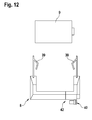
- Fig. 12 shows a retractable battery compartment 8 for the knob 1.
- the battery compartment 8 is a battery 9, in particular a Tekcell CR2 lithium battery, can be used, the battery 9 is contacted by Batteriekontanten 39 of the battery compartment 8.
- Batteriekontanten 39 of the battery compartment 8.
- a cable of the battery compartment 8 is soldered directly to the battery 9.
- a contacting of the battery 9 takes place exclusively via the battery compartment 8.
- the battery compartment 8 in turn has a battery connector 40, which is arranged on the battery compartment 8, in particular with play, and projects through a lateral opening of the battery recess 23 when the battery compartment 8 is inserted into the battery recess 23.
- the battery connector 40 is connected to the battery contacts 39 or to the soldered to the battery cable 9, so that an electrical contacting of the board 10 via the battery connector 40 takes place.
- the first board portion 57 has a battery mating connector 41 which contacts the battery connector 40 when the battery compartment 8 is inserted into the main body 5 of the rotary knob 1.
- the battery mating connector 41 is arranged in particular directly on the first board part 57.
- the battery connector 40 is formed as a contact socket, wherein the battery mating connector 41 is formed as a plug.
- the battery connector 40 is a plug and the battery mating connector 41 is a contact socket.
- the main body 5 has the battery recess 23, which extends from a first jacket opening 54 to a second jacket opening 55 (cf. Fig. 11 ) and rotationally asymmetric.
- the battery recess 23 may be formed as a blind recess, ie, that the battery recess 23 does not completely penetrate the base body 5.
- the battery recess 23 is oriented perpendicular to the first shell opening 54 and the second shell opening 55. This allows the insertion of the battery compartment 8 through the first shell opening 54 into the battery recess 23, as in FIG Fig. 13 shown.
- an outer contour of the first casing opening 54 serves as a preliminary direction for the battery compartment 8. Furthermore, the alignment of the battery compartment 8 in the battery recess 23 in the insertion direction is predetermined by the rotationally asymmetrical design of the battery recess 23. As a result, the insertion of the battery compartment 8 in the battery recess 23 is simplified. For removing the battery compartment 8 from the battery recess 23, a force can be applied to the battery compartment 8 through the second casing opening 55, so that the battery compartment 8 can be removed from the battery recess 23 through the first casing opening 54.
- the second shell opening 55 can be replaced by a spring-loaded locking mechanism.
- the lateral surface 20 of the main body 5 only the first shell opening 54, through which the battery compartment 8 is inserted into the battery recess 23.
- the battery compartment 8 is spring-loaded latched within the battery recess 23, so that by releasing the latch, the spring load can be used to remove the battery compartment 8 from the battery recess 23 again.
- the insertion of the battery compartment 8 in the battery recess 23 is limited by a battery stop 42.
- the battery stop 42 is applied to a base body stop 43, when the battery compartment 8 is completely inserted into the battery recess 23.
- the Battery connector 40 contacted by the battery mating connector 41.
- Fig. 13 it is shown that the main body 5 is surrounded by a cover 6.
- the cover 6 is also in together with the main body 5 in Fig. 14 shown.
- the cover member 6 surrounds the lateral surface 20 of the base body 5, wherein at least one peripheral opening 30 of the cover 6 allows access to the first shell opening 54 and / or to the second shell opening 55 of the base body 5.
- the cover 6 is in particular designed such that by a rotation of the cover 6 relative to the base 5, the first shell opening 54 and / or the second shell opening 55 of the base 5 are covered by the cover 6, ie the peripheral openings 30 of the cover 6 and the first shell opening 54 and / or the second shell opening 55 of the main body 5 are no longer aligned.
- the cover 6 also serves in addition to covering the flange 76, so that the connection between the raster shaft 11 and body 5 is completely covered by the cover 6.
- the raster shaft 11 is guided through an end opening 31 of the cover 6.
- the cover 6 may have a rib in the axial direction, which engages in a corresponding recess, in particular groove. In this way, a radial fixation is realized.
- the arranged in the battery recess 23 battery compartment 8 is particularly advantageous concealable by a knob cap 7, as in Fig. 15 is shown.
- the battery recess 23 through the end openings 30 of Covering element 6 is always released and is only covered by the knob cap 7.
- the knob cap 7 has a connecting element 38, which is designed in particular as a latching lug. With the connecting element 38, the knob cap 7 can be fastened to the main body 5.
- the locking element formed as a connecting element 38 engages in the battery recess 23 and the knob cap 7 thus positively connected to the base body 5.
- the knob cap 7 is arranged under the cover 6, that is arranged closer to the lateral surface 20 of the base body 5 than the cover 6. About a peripheral seal 35, the peripheral openings 30 of the cover 6 are closed. Overall, therefore, the cover 6 and the knob cap 7 together allow a complete and secure cover of the lateral surface 20 of the base body fifth
- the knob cap 7 also has a light ring 36 which is arranged in a cover 77.
- the light ring 36 is glued into the knob cap 7.
- the luminous ring 36 may be clipped into the knob cap 7.
- the cover plate 77 covers the second end face 52 of the main body 5.
- the cover plate 77 can be used in particular in an end opening of the knob cap 7.
- a logo aperture 78 is aufklebbar. The logo aperture 78 therefore gives the knob cap 7 and thus the knob 1 a visually high-quality impression, wherein the light ring 36 is still visible around the logo aperture 78.
- the light ring is in particular driven by the second board part 61.
- an RFID antenna is arranged, which is electrically connected to the second board part 61.
- a radio antenna in particular an 868 MHz antenna, is also arranged. This is used for communication with other components, in particular for the configuration of the rotary knob 1.
- Fig. 16 shows the knob 1 with the Fig. 15
- Knob cap 7 shown on mounting elements 37 both the cover 6 and the knob cap 7 with the main body 5 can be connected. These are in the mounting elements 37 advantageously to threaded pins with pins that are feasible by the cover 6 and the knob cap 7 and screwed within the main body 5.
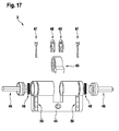
- Fig. 17 shows the cylinder adapter 3 in an exploded view.
- the cylinder adapter 3 comprises a closing element 45 with which a closing mechanism, for example a door, can be actuated.
- the cylinder adapter 3 further has adapter shafts 46, which are connected to the closing element 45. If one of the adapter shafts 46 is rotated, the closing element 45 is also rotated so that the closing mechanism of the door can be actuated by a rotation of the adapter shafts 46.
- a double cylinder is shown, ie the cylinder adapter 3 can be actuated from two sides.
- the cylinder adapter 3 can be actuated from two sides.
- the invention is also possible to use a half-cylinder, in which case the in Fig. 18 shown inner knob 4 is not needed.
- the adapter shaft 46 is secured by a shaft lock 49 within the cylinder adapter 3.
- the adapter shaft 46 has an outer profile, which coincides with the inner profile of the coupling shaft 12.
- torque is transferable from the clutch shaft 12 to the adapter shaft 46.
- said profiles are hexagonal profiles.
- locking elements 47 are provided in particular.
- the locking elements 47 are arranged in clip sleeves 50 and are spring-loaded by a spring 48 in the circumferential grooves 53 of the raster shaft 11 is pressed.
- the circumferential grooves 53 of the raster shaft 11 have chamfers, so that a sawtooth on the outside of the raster shaft 11 is present. This is the knob 1 simply inserted into the cylinder adapter 3.
- the locking element 47 must be pulled out of the circumferential groove 53, which causes a partial removal of the cylinder adapter 3 from the door panel.
- a manipulation of the lock cylinder 2 according to the invention is excluded or at least difficult.
- the rotary knob 1 is telescopic, d. H. the knob 1 can be used for cylinder adapter 3 with different lengths. Due to the adjustability of the knob 1, the knob can be adapted to different door thicknesses.
- the lock cylinder 2 additionally has an inner knob 4, which in Fig. 18 is shown.
- the inner knob 4 has an inner knob body 80, which is connected via a shaft-hub connection 81, in particular by a Scheibfeder für, with an inner shaft 82.
- the inner shaft 82 has, analogous to the coupling shaft 12, an inner profile which coincides with the outer profile of the adapter shafts 46.
- the inner shaft 82 analogous to the raster shaft 11, circumferential grooves on the outer surface.
- the inner knob 4 in the same way to the cylinder adapter 3 can be attached as the knob 1.
- the inner knob 4 always allows the actuation of the cylinder adapter 3, that is, the rotation of the closing element 45th
- Fig. 19 shows the final composition of the lock cylinder 2.
- a rotary knob 1 and an inner knob 4 is used for the actuation of the cylinder adapter 3.
- the invention also provides that for actuating the cylinder adapter 3, two rotary knob 1 can be used.
- a spacer 83 is finally provided. The attachment of the raster shaft 11 of the rotary knob 1 within the cylinder adapter 3 then takes place as in relation to Fig. 17 has been described.
Landscapes
- Physics & Mathematics (AREA)
- Electromagnetism (AREA)
- Lock And Its Accessories (AREA)
Priority Applications (2)
| Application Number | Priority Date | Filing Date | Title |
|---|---|---|---|
| EP14185852.2A EP2998483A1 (fr) | 2014-09-22 | 2014-09-22 | Bouton rotatif destiné à actionner un adaptateur de cylindre d'un barillet |
| DE102015111940.4A DE102015111940A1 (de) | 2014-09-22 | 2015-07-22 | Drehknauf zum Betätigen eines Zylinderadapters eines Schließzylinders |
Applications Claiming Priority (1)
| Application Number | Priority Date | Filing Date | Title |
|---|---|---|---|
| EP14185852.2A EP2998483A1 (fr) | 2014-09-22 | 2014-09-22 | Bouton rotatif destiné à actionner un adaptateur de cylindre d'un barillet |
Publications (1)
| Publication Number | Publication Date |
|---|---|
| EP2998483A1 true EP2998483A1 (fr) | 2016-03-23 |
Family
ID=51582308
Family Applications (1)
| Application Number | Title | Priority Date | Filing Date |
|---|---|---|---|
| EP14185852.2A Withdrawn EP2998483A1 (fr) | 2014-09-22 | 2014-09-22 | Bouton rotatif destiné à actionner un adaptateur de cylindre d'un barillet |
Country Status (2)
| Country | Link |
|---|---|
| EP (1) | EP2998483A1 (fr) |
| DE (1) | DE102015111940A1 (fr) |
Cited By (10)
| Publication number | Priority date | Publication date | Assignee | Title |
|---|---|---|---|---|
| CN106958385A (zh) * | 2017-05-04 | 2017-07-18 | 深圳奥登科技有限公司 | 一种有匙数字智控锁芯 |
| US20180051480A1 (en) * | 2016-08-17 | 2018-02-22 | Amesbury Group, Inc. | Locking system having an electronic deadbolt |
| US10662675B2 (en) | 2017-04-18 | 2020-05-26 | Amesbury Group, Inc. | Modular electronic deadbolt systems |
| US20200291683A1 (en) * | 2017-11-02 | 2020-09-17 | Iloq Oy | Electromechanical lock utilizing magnetic field forces |
| US10808424B2 (en) | 2017-05-01 | 2020-10-20 | Amesbury Group, Inc. | Modular multi-point lock |
| US11066850B2 (en) | 2017-07-25 | 2021-07-20 | Amesbury Group, Inc | Access handle for sliding doors |
| CN113958201A (zh) * | 2021-10-09 | 2022-01-21 | 深圳市凯迪仕智能科技有限公司 | 门锁结构、门锁 |
| US11441333B2 (en) | 2018-03-12 | 2022-09-13 | Amesbury Group, Inc. | Electronic deadbolt systems |
| US11661771B2 (en) | 2018-11-13 | 2023-05-30 | Amesbury Group, Inc. | Electronic drive for door locks |
| US11834866B2 (en) | 2018-11-06 | 2023-12-05 | Amesbury Group, Inc. | Flexible coupling for electronic deadbolt systems |
Citations (4)
| Publication number | Priority date | Publication date | Assignee | Title |
|---|---|---|---|---|
| DE19854454A1 (de) * | 1998-11-13 | 2000-06-08 | Ulf Klenk | Schließzylinder |
| DE102004009992A1 (de) * | 2004-03-01 | 2005-09-22 | Mehmet Sancak | Handhabe für ein Türschloss und Schloss mit derartiger Handhabe |
| DE102012020451A1 (de) * | 2012-10-17 | 2014-04-17 | Dorma Gmbh + Co. Kg | System mit Türbetätigungsteil und Schließzylinder |
| WO2014060531A1 (fr) * | 2012-10-17 | 2014-04-24 | Dorma Gmbh + Co. Kg | Partie d'actionnement de porte dotée d'un raccord intégré |
-
2014
- 2014-09-22 EP EP14185852.2A patent/EP2998483A1/fr not_active Withdrawn
-
2015
- 2015-07-22 DE DE102015111940.4A patent/DE102015111940A1/de not_active Withdrawn
Patent Citations (4)
| Publication number | Priority date | Publication date | Assignee | Title |
|---|---|---|---|---|
| DE19854454A1 (de) * | 1998-11-13 | 2000-06-08 | Ulf Klenk | Schließzylinder |
| DE102004009992A1 (de) * | 2004-03-01 | 2005-09-22 | Mehmet Sancak | Handhabe für ein Türschloss und Schloss mit derartiger Handhabe |
| DE102012020451A1 (de) * | 2012-10-17 | 2014-04-17 | Dorma Gmbh + Co. Kg | System mit Türbetätigungsteil und Schließzylinder |
| WO2014060531A1 (fr) * | 2012-10-17 | 2014-04-24 | Dorma Gmbh + Co. Kg | Partie d'actionnement de porte dotée d'un raccord intégré |
Cited By (13)
| Publication number | Priority date | Publication date | Assignee | Title |
|---|---|---|---|---|
| US20180051480A1 (en) * | 2016-08-17 | 2018-02-22 | Amesbury Group, Inc. | Locking system having an electronic deadbolt |
| US10968661B2 (en) * | 2016-08-17 | 2021-04-06 | Amesbury Group, Inc. | Locking system having an electronic deadbolt |
| US10662675B2 (en) | 2017-04-18 | 2020-05-26 | Amesbury Group, Inc. | Modular electronic deadbolt systems |
| US11634931B2 (en) | 2017-04-18 | 2023-04-25 | Amesbury Group, Inc. | Modular electronic deadbolt systems |
| US10808424B2 (en) | 2017-05-01 | 2020-10-20 | Amesbury Group, Inc. | Modular multi-point lock |
| CN106958385A (zh) * | 2017-05-04 | 2017-07-18 | 深圳奥登科技有限公司 | 一种有匙数字智控锁芯 |
| US11066850B2 (en) | 2017-07-25 | 2021-07-20 | Amesbury Group, Inc | Access handle for sliding doors |
| US20200291683A1 (en) * | 2017-11-02 | 2020-09-17 | Iloq Oy | Electromechanical lock utilizing magnetic field forces |
| US11808057B2 (en) * | 2017-11-02 | 2023-11-07 | Iloq Oy | Electromechanical lock utilizing magnetic field forces |
| US11441333B2 (en) | 2018-03-12 | 2022-09-13 | Amesbury Group, Inc. | Electronic deadbolt systems |
| US11834866B2 (en) | 2018-11-06 | 2023-12-05 | Amesbury Group, Inc. | Flexible coupling for electronic deadbolt systems |
| US11661771B2 (en) | 2018-11-13 | 2023-05-30 | Amesbury Group, Inc. | Electronic drive for door locks |
| CN113958201A (zh) * | 2021-10-09 | 2022-01-21 | 深圳市凯迪仕智能科技有限公司 | 门锁结构、门锁 |
Also Published As
| Publication number | Publication date |
|---|---|
| DE102015111940A1 (de) | 2016-03-24 |
Similar Documents
| Publication | Publication Date | Title |
|---|---|---|
| EP2998483A1 (fr) | Bouton rotatif destiné à actionner un adaptateur de cylindre d'un barillet | |
| EP2668062B1 (fr) | Dispositif de verrouillage, notamment pour un connecteur | |
| EP2212502B1 (fr) | Mécanisme d'entraînement pour porte avec unité d'entraînement | |
| EP2436858B1 (fr) | Cylindre de fermeture pour un verrou | |
| EP2998485B1 (fr) | Bouton rotatif destine a actionner un adaptateur de cylindre d'un barillet | |
| DE102018202563B4 (de) | Knauf für einen elektronischen Schließzylinder | |
| DE112008002710B4 (de) | Schlossbetätigung und Schloss, welches eine solche Betätigung verwendet | |
| DE102015110531A1 (de) | Türgriffsystem für Fahrzeuge | |
| EP1712716A2 (fr) | Verrou rotatif résistant aux vibrations | |
| DE102010018243A1 (de) | Schließzylinderanordnung | |
| EP2042671A2 (fr) | Fixation de poignée et ferrure avec une fixation de poignée | |
| DE102007011554B4 (de) | Koppeleinheit für elektronische Schließ-Systeme | |
| DE102015111937A1 (de) | Drehknauf zum Betätigen eines Zylinderadapters eines Schließzylinders | |
| EP2998486A1 (fr) | Bouton rotatif destine a actionner un adaptateur de cylindre d'un barillet | |
| EP2998482A1 (fr) | Bouton rotatif destiné à actionner un adaptateur de cylindre d'un barillet | |
| DE102010014207A1 (de) | Schlüsselvorrichtung | |
| EP2998463B1 (fr) | Armature pour une porte de bâtiment et procédé | |
| DE102015109914A1 (de) | Elektromechanisches Zugangskontrollsystem und Verfahren | |
| DE102013205061A1 (de) | Bedienungsmittel für eine Platte, Kombination zweier Bedienungsmittel und Verfahren zum klemmfesten Positionieren des Bedienungsmittels an einer Platte | |
| DE102015111943A1 (de) | Drehknauf zum Betätigen eines Zylinderadapters eines Schließzylinders | |
| DE102015109904A1 (de) | Beschlag für eine Gebäudetür und ein Verfahren hierfür | |
| DE102007013689B3 (de) | Explosionsgeschütztes Gehäuse mit trennbarer Schalterwelle | |
| EP2980338B1 (fr) | Systeme de cylindre de serrure | |
| EP2998479B1 (fr) | Armature pour une porte de bâtiment dotée d'une poignée | |
| EP2998481B1 (fr) | Système de contrôle d'accès électromécanique |
Legal Events
| Date | Code | Title | Description |
|---|---|---|---|
| PUAI | Public reference made under article 153(3) epc to a published international application that has entered the european phase |
Free format text: ORIGINAL CODE: 0009012 |
|
| AK | Designated contracting states |
Kind code of ref document: A1 Designated state(s): AL AT BE BG CH CY CZ DE DK EE ES FI FR GB GR HR HU IE IS IT LI LT LU LV MC MK MT NL NO PL PT RO RS SE SI SK SM TR |
|
| AX | Request for extension of the european patent |
Extension state: BA ME |
|
| 17P | Request for examination filed |
Effective date: 20160921 |
|
| RBV | Designated contracting states (corrected) |
Designated state(s): AL AT BE BG CH CY CZ DE DK EE ES FI FR GB GR HR HU IE IS IT LI LT LU LV MC MK MT NL NO PL PT RO RS SE SI SK SM TR |
|
| RAP1 | Party data changed (applicant data changed or rights of an application transferred) |
Owner name: DORMAKABA DEUTSCHLAND GMBH |
|
| RIC1 | Information provided on ipc code assigned before grant |
Ipc: E05B 47/06 20060101AFI20190418BHEP |
|
| GRAP | Despatch of communication of intention to grant a patent |
Free format text: ORIGINAL CODE: EPIDOSNIGR1 |
|
| STAA | Information on the status of an ep patent application or granted ep patent |
Free format text: STATUS: GRANT OF PATENT IS INTENDED |
|
| INTG | Intention to grant announced |
Effective date: 20190606 |
|
| STAA | Information on the status of an ep patent application or granted ep patent |
Free format text: STATUS: THE APPLICATION IS DEEMED TO BE WITHDRAWN |
|
| 18D | Application deemed to be withdrawn |
Effective date: 20191017 |