EP2998517B1 - Agencement d'étanchéité au niveau de l'interface entre une chambre de combustion et une turbine d'une turbine à gaz et turbine à gaz avec un tel agencement d'étanchéité - Google Patents
Agencement d'étanchéité au niveau de l'interface entre une chambre de combustion et une turbine d'une turbine à gaz et turbine à gaz avec un tel agencement d'étanchéité Download PDFInfo
- Publication number
- EP2998517B1 EP2998517B1 EP14185021.4A EP14185021A EP2998517B1 EP 2998517 B1 EP2998517 B1 EP 2998517B1 EP 14185021 A EP14185021 A EP 14185021A EP 2998517 B1 EP2998517 B1 EP 2998517B1
- Authority
- EP
- European Patent Office
- Prior art keywords
- vane
- turbine
- guiding
- sealing arrangement
- seal
- Prior art date
- Legal status (The legal status is an assumption and is not a legal conclusion. Google has not performed a legal analysis and makes no representation as to the accuracy of the status listed.)
- Active
Links
Images


Classifications
-
- F—MECHANICAL ENGINEERING; LIGHTING; HEATING; WEAPONS; BLASTING
- F02—COMBUSTION ENGINES; HOT-GAS OR COMBUSTION-PRODUCT ENGINE PLANTS
- F02C—GAS-TURBINE PLANTS; AIR INTAKES FOR JET-PROPULSION PLANTS; CONTROLLING FUEL SUPPLY IN AIR-BREATHING JET-PROPULSION PLANTS
- F02C7/00—Features, components parts, details or accessories, not provided for in, or of interest apart form groups F02C1/00 - F02C6/00; Air intakes for jet-propulsion plants
- F02C7/28—Arrangement of seals
-
- F—MECHANICAL ENGINEERING; LIGHTING; HEATING; WEAPONS; BLASTING
- F01—MACHINES OR ENGINES IN GENERAL; ENGINE PLANTS IN GENERAL; STEAM ENGINES
- F01D—NON-POSITIVE DISPLACEMENT MACHINES OR ENGINES, e.g. STEAM TURBINES
- F01D9/00—Stators
- F01D9/02—Nozzles; Nozzle boxes; Stator blades; Guide conduits, e.g. individual nozzles
- F01D9/023—Transition ducts between combustor cans and first stage of the turbine in gas-turbine engines; their cooling or sealings
-
- F—MECHANICAL ENGINEERING; LIGHTING; HEATING; WEAPONS; BLASTING
- F02—COMBUSTION ENGINES; HOT-GAS OR COMBUSTION-PRODUCT ENGINE PLANTS
- F02C—GAS-TURBINE PLANTS; AIR INTAKES FOR JET-PROPULSION PLANTS; CONTROLLING FUEL SUPPLY IN AIR-BREATHING JET-PROPULSION PLANTS
- F02C3/00—Gas-turbine plants characterised by the use of combustion products as the working fluid
- F02C3/04—Gas-turbine plants characterised by the use of combustion products as the working fluid having a turbine driving a compressor
-
- F—MECHANICAL ENGINEERING; LIGHTING; HEATING; WEAPONS; BLASTING
- F02—COMBUSTION ENGINES; HOT-GAS OR COMBUSTION-PRODUCT ENGINE PLANTS
- F02C—GAS-TURBINE PLANTS; AIR INTAKES FOR JET-PROPULSION PLANTS; CONTROLLING FUEL SUPPLY IN AIR-BREATHING JET-PROPULSION PLANTS
- F02C9/00—Controlling gas-turbine plants; Controlling fuel supply in air- breathing jet-propulsion plants
- F02C9/16—Control of working fluid flow
- F02C9/20—Control of working fluid flow by throttling; by adjusting vanes
- F02C9/22—Control of working fluid flow by throttling; by adjusting vanes by adjusting turbine vanes
-
- F—MECHANICAL ENGINEERING; LIGHTING; HEATING; WEAPONS; BLASTING
- F01—MACHINES OR ENGINES IN GENERAL; ENGINE PLANTS IN GENERAL; STEAM ENGINES
- F01D—NON-POSITIVE DISPLACEMENT MACHINES OR ENGINES, e.g. STEAM TURBINES
- F01D11/00—Preventing or minimising internal leakage of working-fluid, e.g. between stages
- F01D11/003—Preventing or minimising internal leakage of working-fluid, e.g. between stages by packing rings; Mechanical seals
-
- F—MECHANICAL ENGINEERING; LIGHTING; HEATING; WEAPONS; BLASTING
- F05—INDEXING SCHEMES RELATING TO ENGINES OR PUMPS IN VARIOUS SUBCLASSES OF CLASSES F01-F04
- F05D—INDEXING SCHEME FOR ASPECTS RELATING TO NON-POSITIVE-DISPLACEMENT MACHINES OR ENGINES, GAS-TURBINES OR JET-PROPULSION PLANTS
- F05D2220/00—Application
- F05D2220/30—Application in turbines
- F05D2220/32—Application in turbines in gas turbines
-
- F—MECHANICAL ENGINEERING; LIGHTING; HEATING; WEAPONS; BLASTING
- F05—INDEXING SCHEMES RELATING TO ENGINES OR PUMPS IN VARIOUS SUBCLASSES OF CLASSES F01-F04
- F05D—INDEXING SCHEME FOR ASPECTS RELATING TO NON-POSITIVE-DISPLACEMENT MACHINES OR ENGINES, GAS-TURBINES OR JET-PROPULSION PLANTS
- F05D2240/00—Components
- F05D2240/10—Stators
- F05D2240/12—Fluid guiding means, e.g. vanes
-
- F—MECHANICAL ENGINEERING; LIGHTING; HEATING; WEAPONS; BLASTING
- F05—INDEXING SCHEMES RELATING TO ENGINES OR PUMPS IN VARIOUS SUBCLASSES OF CLASSES F01-F04
- F05D—INDEXING SCHEME FOR ASPECTS RELATING TO NON-POSITIVE-DISPLACEMENT MACHINES OR ENGINES, GAS-TURBINES OR JET-PROPULSION PLANTS
- F05D2240/00—Components
- F05D2240/55—Seals
-
- F—MECHANICAL ENGINEERING; LIGHTING; HEATING; WEAPONS; BLASTING
- F05—INDEXING SCHEMES RELATING TO ENGINES OR PUMPS IN VARIOUS SUBCLASSES OF CLASSES F01-F04
- F05D—INDEXING SCHEME FOR ASPECTS RELATING TO NON-POSITIVE-DISPLACEMENT MACHINES OR ENGINES, GAS-TURBINES OR JET-PROPULSION PLANTS
- F05D2250/00—Geometry
- F05D2250/20—Three-dimensional
- F05D2250/28—Three-dimensional patterned
- F05D2250/283—Three-dimensional patterned honeycomb
-
- F—MECHANICAL ENGINEERING; LIGHTING; HEATING; WEAPONS; BLASTING
- F23—COMBUSTION APPARATUS; COMBUSTION PROCESSES
- F23R—GENERATING COMBUSTION PRODUCTS OF HIGH PRESSURE OR HIGH VELOCITY, e.g. GAS-TURBINE COMBUSTION CHAMBERS
- F23R3/00—Continuous combustion chambers using liquid or gaseous fuel
- F23R3/42—Continuous combustion chambers using liquid or gaseous fuel characterised by the arrangement or form of the flame tubes or combustion chambers
- F23R3/60—Support structures; Attaching or mounting means
Definitions
- the present invention relates to the technology of gas turbines. It refers to a sealing arrangement at the interface between a combustor and a turbine of a gas turbine according to the preamble of claim 1.
- Gas turbines generally comprise a compressor, a combustor and a turbine.
- the compressor compresses air, which is then fed to a combustor to be used to burn a fuel.
- the resulting hot gas leaves the combustor and enters the turbine along a hot gas path,
- a ring of guiding vanes is arranged at the turbine Inlet.
- seals must be provided at various places along the hot gas path.
- at the interface between the combustor and the turbine special honeycomb seals are used for sealing (see for example document US 7,178,340 ).
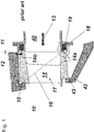
- FIG. 1 The sealing situation at the combustor/turbine interface is shown in detail in Fig. 1 .
- the hot gas path 40 guides hot gas 13 from a combustor 11 to turbine 12 of gas turbine 10 through the combustor/turbine interface.
- a circumferential ring of guiding vanes 14 is arranged at the inlet of turbine 12 .
- Each guiding vane 14 comprises an airfoil 17 extending in radial direction between an inner diameter platform 14a and an outer diameter platform 14b
- the vanes 14 each are hooked into a support at the outer casing by means of a rear outer diameter hook 15 at the rear end of the outer diameter platform 14b (see upper circle in Fig. 1 ).
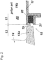
- a sealing arrangement 18 at the front end of the inner diameter platform 14a (see lower circle in Fig. 1 ), where a vane tooth 19 is in sealing engagement with honeycomb seal 20 (shown in even more detail in Fig. 2 ) and its sealing surface 21.
- the vanes 14 are supported on the inner platform by a holding structure 42. Transient thermal behaviour between the inner and the outer structure of the gas turbine lead to relative movement 43.
- the particular requirement to the seal location or sealing arrangement 18 is that relative axial and radial movements have to be accommodated by the seal 20. This is supposed to be done via elastic deformation of the honeycomb. A tight sealing at the sealing arrangement 18 is important to prevent cooling air bypass around the combustor 11 into the hot gas path 40, leading to higher flame temperature and higher NOx emissions and to a larger degree of temperature non-uniformity at the turbine inlet of turbine 12.
- the problem is that ageing and deterioration wears the seal or the seal is plastically deformed Both effects may lead to an increase of the leakage gap.
- US 7 178 340 B2 discloses a sealing arrangement at the interface between a combustor and a turbine of a gas turbine. Guiding vanes of the turbine are mounted within the turbine by an outer vane hook. At their inner diameter, the guiding vanes are in sealing engagement with a honeycomb seal at the outlet of the combustor by means of a front inner vane tooth.
- the outer vane hook allows a relative rotation of the guiding vane around a hooking of the outer diameter vane hook and a rear end of an outer diameter platform of the guiding vanes.
- the sealing arrangement according to the invention is provided at the interface between a combustor and a turbine of a gas turbine, said turbine comprising guiding vanes at its inlet, which guiding vanes are each mounted within said turbine at their outer diameter by means of an rear or close to rear outer diameter vane hook and are each at their inner diameter in sealing engagement by means of a front inner diameter vane tooth with a honeycomb seal arranged at the corresponding inner diameter part of the outlet of said combustor, whereby said rear outer diameter vane hook allows a relative movement of said guiding vane in form of a rotation around said rear outer diameter vane hook.
- said front inner diameter vane tooth and the corresponding honeycomb seal are adapted in their configuration to said rotating relative movement of said guiding vane, such said the compression of said honeycomb seal through transients of the gas turbine is reduced.
- An embodiment of the sealing arrangement according to the invention is characterized in that said front inner diameter vane tooth and the corresponding honeycomb seal are adapted in their shape to said rotating relative movement of said guiding vane.
- said honeycomb seal has a sealing surface, which is in alignment with the tangential direction of the rotating relative movement of said guiding vane.
- said front inner diameter vane tooth has a contacting surface, which is in general alignment with said sealing surface of said honeycomb seal.
- said contacting surface may be parallel with said sealing surface.
- said contacting surface may be more inclined with respect to the axial direction of the machine than said sealing surface.
- Another embodiment of the sealing arrangement according to the invention is characterized in that the honeycomb cells of said honeycomb seal are adapted in their orientation to said rotating relative movement of said guiding vane.
- said honeycomb seal may have a sealing surface in alignment with the tangential direction of the rotating relative movement of said guiding vane, and the honeycomb cells of said honeycomb seal may be all in alignment with the tangential direction of the rotating relative movement of said guiding vane.
- said honeycomb seal may have a sealing surface in alignment with the tangential direction of the rotating relative movement of said guiding vane, and the said honeycomb seal may be pre-deformed such that the honeycomb cells of said honeycomb seal are in growing alignment with the tangential direction of the rotating relative movement of said guiding vane, with decreasing distance from a sealing surface.
- the inventive gas turbine comprises a sealing arrangement according to the invention.
- the basic idea of the present invention is to reduce the compression of the seal through transients through appropriate shaping and/or configuring.
- the dominating relative movement of the vanes 14 is a rotation around the rear outer diameter vane hook 15 with radius vector 16.
- the contacting surface 23a of vane tooth 23 and the sealing surface 25 of honeycomb seal 24 are oriented in parallel to the relative movement of vane 14, or in tangential direction with respect to radius vector 16.
- the direction of compression of the honeycomb is still oriented along the axial direction of the machine for reasons of easy manufacturing and assembly.
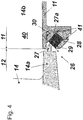
- FIG. 4 Such an alternative design is shown in Fig. 4 .
- the sealing arrangement of Fig. 4 comprises a vane tooth 27 with an inclined contacting surface 27a similar to Fig. 3 and a honeycomb seal 28 with a correspondingly inclined sealing surface 29 similar to Fig. 3 , which is held in a seal carrier 30.
- the seal carrier 30 can be split to reduce clearance between seal 28 and seal carrier 30.
- the direction of compression is radial to the centre of rotation of the vane 14, i.e. the rear outer diameter hook 15.
- the honeycomb cells are also inclined in accordance with the lines drawn in seal 28. This minimizes radial forces to the seal which is beneficial to reduce leakage with a seal that has increased clearance, for both, design clearance and degraded material.
- FIG. 5 An alternative design for the vane tooth is shown in Fig. 5 .
- the edge of vane tooth 32 is produced with an angle ⁇ (for example 50°), which is bigger than angle ⁇ (for example 45°) of the inclined sealing surface 34 such that the seal crush is a distance d (for example of ⁇ 1 mm) higher in the bottom part than in the top part of tooth 32.
- ⁇ for example 50°
- ⁇ for example 45°
- d for example of ⁇ 1 mm
- FIG. 6 An alternative design is shown in Fig 6 .
- the honeycomb cells 38 of the honeycomb seal 36 with its inclined sealing surface 37 are pre-deformed (see the block arrow in Fig. 6 ) to get the desired end shape.
- Final machining of the outer and inner sealing interfaces can be done before or preferably after pre-bending. This allows the height of the honeycomb seal to be reduced to a minimum which is beneficial for manufacturing.
- the honeycomb When compressed, the honeycomb elongates circumferentially. This space must be provided in the design and creates an additional leakage path. Less compression means also that less circumferential space has to be provided, which means less secondary leakage.
Landscapes
- Engineering & Computer Science (AREA)
- Chemical & Material Sciences (AREA)
- Combustion & Propulsion (AREA)
- Mechanical Engineering (AREA)
- General Engineering & Computer Science (AREA)
- Physics & Mathematics (AREA)
- Fluid Mechanics (AREA)
- Sealing Using Fluids, Sealing Without Contact, And Removal Of Oil (AREA)
- Turbine Rotor Nozzle Sealing (AREA)
Claims (5)
- Agencement d'étanchéité (22, 26, 31) au niveau de l'interface entre une chambre de combustion (11) et une turbine (12) d'une turbine à gaz (10), ladite turbine (12) comprenant des pales de guidage (14) au niveau de son entrée, lesquelles pales de guidage (14) sont chacune montées à l'intérieur de ladite turbine (12) au niveau de leur diamètre externe au moyen d'un crochet de pale de diamètre externe (15) et sont chacune, au niveau de leur diamètre interne, en mise en prise d'étanchéité au moyen d'une dent de pale de diamètre interne avant (23, 27, 32) avec un joint d'étanchéité en nid d'abeille (24, 28, 33, 36) agencé au niveau de la partie de diamètre interne correspondante de la sortie de ladite chambre de combustion (11), de sorte que ledit crochet de pale de diamètre externe arrière (15) permet une rotation relative (16) de ladite pale de guidage (14) autour d'un accrochage dudit crochet de pale de diamètre externe (15) et d'une extrémité arrière d'une plateforme de diamètre externe (14b) de ladite pale de guidage (14) avec le rayon vecteur (16) allant dudit accrochage à ladite dent de pale de diamètre interne avant (23, 27, 32), caractérisé en ce que ledit joint d'étanchéité en nid d'abeille (24, 28, 33, 36) a une surface d'étanchéité (25, 29, 34, 37) qui est alignée avec la direction tangentielle de la rotation relative (16) de ladite pale de guidage (14) et ladite dent de pale de diamètre interne avant (23, 27, 32) a une surface de contact (23a, 27a, 32a), ladite surface de contact (32a) forme un angle (β) par rapport à la direction axiale de la machine qui est supérieur à un angle (α) formé par ladite surface d'étanchéité (34), de sorte que ladite dent de pale de diamètre interne avant (23, 27, 32) et le joint d'étanchéité en nid d'abeille (24, 28, 33, 36) correspondant sont adaptés dans leur configuration et leur forme à ladite rotation relative de ladite pale de guidage (14), de sorte que ladite compression dudit joint d'étanchéité en nid d'abeille (24, 28, 33, 36) à travers les transitoires de la turbine à gaz (10) est réduite.
- Agencement d'étanchéité selon la revendication 1, caractérisé en ce que ledit joint d'étanchéité en nid d'abeille (28) a une surface d'étanchéité (29) alignée avec la direction tangentielle de la rotation relative (16) de ladite pale de guidage (14), et en ce que des cellules alvéolaires dudit joint d'étanchéité en nid d'abeille (28) sont toutes alignées avec la direction tangentielle de la rotation relative (16) de ladite pale de guidage (14).
- Agencement d'étanchéité selon la revendication 1, caractérisé en ce que ledit joint d'étanchéité en nid d'abeille (36) a une surface d'étanchéité (37) alignée avec la direction tangentielle du mouvement rotatif relatif (16) de ladite pale de guidage (14), et en ce que ledit joint d'étanchéité en nid d'abeille (16) est déformé préalablement de sorte que les cellules alvéolaires (38) dudit joint d'étanchéité en nid d'abeille (36) présentent un alignement croissant dans la direction tangentielle du mouvement rotatif relatif (16) de ladite pale de guidage (14), avec la distance décroissante à partir de la surface d'étanchéité (37).
- Agencement d'étanchéité selon la revendication 1, caractérisé en ce que ledit crochet de pale de diamètre externe (15) est agencé au niveau de l'extrémité arrière ou à proximité de l'extrémité arrière de la pale (14).
- Turbine à gaz (10) comprenant un agencement d'étanchéité (22, 26, 31) selon l'une quelconque des revendications 1 à 4.
Priority Applications (4)
| Application Number | Priority Date | Filing Date | Title |
|---|---|---|---|
| EP14185021.4A EP2998517B1 (fr) | 2014-09-16 | 2014-09-16 | Agencement d'étanchéité au niveau de l'interface entre une chambre de combustion et une turbine d'une turbine à gaz et turbine à gaz avec un tel agencement d'étanchéité |
| US14/851,397 US10393025B2 (en) | 2014-09-16 | 2015-09-11 | Sealing arrangement at the interface between a combustor and a turbine of a gas turbine and gas turbine with such a sealing arrangement |
| JP2015182850A JP2016061294A (ja) | 2014-09-16 | 2015-09-16 | ガスタービンの燃焼器とタービンとの間の境界面におけるシール配列及びこのようなシール配列を備えるガスタービン |
| CN201510587931.0A CN105422286B (zh) | 2014-09-16 | 2015-09-16 | 密封组件及具有此密封组件的燃气涡轮 |
Applications Claiming Priority (1)
| Application Number | Priority Date | Filing Date | Title |
|---|---|---|---|
| EP14185021.4A EP2998517B1 (fr) | 2014-09-16 | 2014-09-16 | Agencement d'étanchéité au niveau de l'interface entre une chambre de combustion et une turbine d'une turbine à gaz et turbine à gaz avec un tel agencement d'étanchéité |
Publications (2)
| Publication Number | Publication Date |
|---|---|
| EP2998517A1 EP2998517A1 (fr) | 2016-03-23 |
| EP2998517B1 true EP2998517B1 (fr) | 2019-03-27 |
Family
ID=51564506
Family Applications (1)
| Application Number | Title | Priority Date | Filing Date |
|---|---|---|---|
| EP14185021.4A Active EP2998517B1 (fr) | 2014-09-16 | 2014-09-16 | Agencement d'étanchéité au niveau de l'interface entre une chambre de combustion et une turbine d'une turbine à gaz et turbine à gaz avec un tel agencement d'étanchéité |
Country Status (3)
| Country | Link |
|---|---|
| US (1) | US10393025B2 (fr) |
| EP (1) | EP2998517B1 (fr) |
| JP (1) | JP2016061294A (fr) |
Families Citing this family (8)
| Publication number | Priority date | Publication date | Assignee | Title |
|---|---|---|---|---|
| US9598981B2 (en) * | 2013-11-22 | 2017-03-21 | Siemens Energy, Inc. | Industrial gas turbine exhaust system diffuser inlet lip |
| FR3052494B1 (fr) * | 2016-06-09 | 2018-06-15 | Safran Aircraft Engines | Etage redresseur a calage variable pour compresseur de turbomachine comportant un joint d'etancheite sur carter externe et/ou anneau interne |
| US9816388B1 (en) * | 2016-09-22 | 2017-11-14 | General Electric Company | Seal in a gas turbine engine having a shim base and a honeycomb structure with a number of cavities formed therein |
| EP3306037B1 (fr) | 2016-10-06 | 2019-05-29 | Ansaldo Energia Switzerland AG | Turbine à gaz dotée d'un dispositif d'étanchéité à l'interface entre la chambre de combustion et la turbine |
| EP3421726B1 (fr) * | 2017-06-30 | 2020-12-30 | Ansaldo Energia Switzerland AG | Cadre d'image de connexion d'une chambre de combustion à une turbine dans une turbine à gaz et turbine à gaz comprenant un cadre d'image |
| US10941672B2 (en) | 2018-09-14 | 2021-03-09 | DOOSAN Heavy Industries Construction Co., LTD | Stationary vane nozzle of gas turbine |
| EP3945246B1 (fr) * | 2020-07-27 | 2024-02-07 | Ansaldo Energia Switzerland AG | Turbine à gaz pour centrales électriques doté d'un dispositif d'étanchéité en nid d'abeilles |
| CN117272538B (zh) * | 2023-09-22 | 2024-01-19 | 成都岷山绿氢能源有限公司 | 压缩机导流叶片加工方法、导流机构和离心式压缩机 |
Family Cites Families (40)
| Publication number | Priority date | Publication date | Assignee | Title |
|---|---|---|---|---|
| US2592060A (en) * | 1946-03-25 | 1952-04-08 | Rolls Royce | Mounting of combustion chambers in jet-propulsion and gas-turbine power-units |
| GB1385666A (en) | 1973-07-06 | 1975-02-26 | Rolls Royce | Sealing of vaned assemblies of gas turbine engines |
| US3966353A (en) * | 1975-02-21 | 1976-06-29 | Westinghouse Electric Corporation | Ceramic-to-metal (or ceramic) cushion/seal for use with three piece ceramic stationary vane assembly |
| US4768924A (en) * | 1986-07-22 | 1988-09-06 | Pratt & Whitney Canada Inc. | Ceramic stator vane assembly |
| US4863343A (en) | 1988-05-16 | 1989-09-05 | Westinghouse Electric Corp. | Turbine vane shroud sealing system |
| DE59202211D1 (de) * | 1991-08-08 | 1995-06-22 | Asea Brown Boveri | Deckblatt für axialdurchströmte Turbine. |
| DE59201833D1 (de) * | 1991-10-08 | 1995-05-11 | Asea Brown Boveri | Deckband für axialdurchströmte Turbine. |
| US5215435A (en) * | 1991-10-28 | 1993-06-01 | General Electric Company | Angled cooling air bypass slots in honeycomb seals |
| US5358374A (en) * | 1993-07-21 | 1994-10-25 | General Electric Company | Turbine nozzle backflow inhibitor |
| EP0844369B1 (fr) * | 1996-11-23 | 2002-01-30 | ROLLS-ROYCE plc | Assemblage d'un rotor à aubes et de son carter |
| US5785492A (en) * | 1997-03-24 | 1998-07-28 | United Technologies Corporation | Method and apparatus for sealing a gas turbine stator vane assembly |
| DE19821365C2 (de) * | 1998-05-13 | 2001-09-13 | Man Turbomasch Ag Ghh Borsig | Kühlung einer Wabendichtung im mit Heißgas beaufschlagten Teil einer Gasturbine |
| DE19828065A1 (de) * | 1998-06-24 | 1999-12-30 | Bmw Rolls Royce Gmbh | Wabenstruktur-Dichtung insbesondere für eine Gasturbine |
| US6471216B1 (en) * | 1999-05-24 | 2002-10-29 | General Electric Company | Rotating seal |
| EP1247943A1 (fr) * | 2001-04-04 | 2002-10-09 | Siemens Aktiengesellschaft | Segment de virole réfroidi pour turbine à gaz |
| US6547257B2 (en) * | 2001-05-04 | 2003-04-15 | General Electric Company | Combination transition piece floating cloth seal and stage 1 turbine nozzle flexible sealing element |
| DE10295864D2 (de) * | 2001-12-14 | 2004-11-04 | Alstom Technology Ltd Baden | Gasturbinenanordnung |
| US7178340B2 (en) | 2003-09-24 | 2007-02-20 | Power Systems Mfg., Llc | Transition duct honeycomb seal |
| US6942445B2 (en) | 2003-12-04 | 2005-09-13 | Honeywell International Inc. | Gas turbine cooled shroud assembly with hot gas ingestion suppression |
| DE10359730A1 (de) * | 2003-12-19 | 2005-07-14 | Mtu Aero Engines Gmbh | Turbomaschine, insbesondere Gasturbine |
| JP4412081B2 (ja) * | 2004-07-07 | 2010-02-10 | 株式会社日立製作所 | ガスタービンとガスタービンの冷却方法 |
| DE102004034312A1 (de) * | 2004-07-15 | 2006-02-02 | Mtu Aero Engines Gmbh | Dichtungsanordnung und Verfahren zur Herstellung eines Dichtkörpers für eine Dichtungsanordnung |
| FR2882394B1 (fr) * | 2005-02-22 | 2007-05-18 | Snecma Moteurs Sa | Dispositif de variation de la section de col d'un distributeur de turbine |
| US7329087B2 (en) | 2005-09-19 | 2008-02-12 | General Electric Company | Seal-less CMC vane to platform interfaces |
| US20070273104A1 (en) * | 2006-05-26 | 2007-11-29 | Siemens Power Generation, Inc. | Abradable labyrinth tooth seal |
| US20080061515A1 (en) * | 2006-09-08 | 2008-03-13 | Eric Durocher | Rim seal for a gas turbine engine |
| GB2445565A (en) * | 2006-09-26 | 2008-07-16 | Siemens Ag | Gas turbine engine having a plurality of modules comprising a combustor and transition duct |
| US8167547B2 (en) | 2007-03-05 | 2012-05-01 | United Technologies Corporation | Gas turbine engine with canted pocket and canted knife edge seal |
| US20090014964A1 (en) * | 2007-07-09 | 2009-01-15 | Siemens Power Generation, Inc. | Angled honeycomb seal between turbine rotors and turbine stators in a turbine engine |
| US8230535B2 (en) * | 2009-01-07 | 2012-07-31 | Noble Company | Shower base apparatus |
| EP2282012B1 (fr) * | 2009-07-03 | 2015-11-25 | Alstom Technology Ltd | Procédé de remplacement d'un couvercle d'une aube directrice d'une turbine à gaz |
| US8388307B2 (en) * | 2009-07-21 | 2013-03-05 | Honeywell International Inc. | Turbine nozzle assembly including radially-compliant spring member for gas turbine engine |
| US20130052024A1 (en) | 2011-08-24 | 2013-02-28 | General Electric Company | Turbine Nozzle Vane Retention System |
| IN2014DN03773A (fr) * | 2011-10-24 | 2015-07-10 | Alstom Technology Ltd | |
| US9145788B2 (en) * | 2012-01-24 | 2015-09-29 | General Electric Company | Retrofittable interstage angled seal |
| US9574455B2 (en) * | 2012-07-16 | 2017-02-21 | United Technologies Corporation | Blade outer air seal with cooling features |
| EP2886801B1 (fr) * | 2013-12-20 | 2019-04-24 | Ansaldo Energia IP UK Limited | Système d'étanchéité pour une turbine à gaz et turbine à gaz associée |
| EP3026218B1 (fr) * | 2014-11-27 | 2017-06-14 | Ansaldo Energia Switzerland AG | Dispositif d'aube du premier étage de turbine |
| EP3073058B1 (fr) * | 2015-03-27 | 2020-06-10 | Ansaldo Energia Switzerland AG | Agencements d'étanchéité dans des turbines à gaz |
| EP3306037B1 (fr) * | 2016-10-06 | 2019-05-29 | Ansaldo Energia Switzerland AG | Turbine à gaz dotée d'un dispositif d'étanchéité à l'interface entre la chambre de combustion et la turbine |
-
2014
- 2014-09-16 EP EP14185021.4A patent/EP2998517B1/fr active Active
-
2015
- 2015-09-11 US US14/851,397 patent/US10393025B2/en active Active
- 2015-09-16 JP JP2015182850A patent/JP2016061294A/ja active Pending
Non-Patent Citations (1)
| Title |
|---|
| None * |
Also Published As
| Publication number | Publication date |
|---|---|
| US20160076454A1 (en) | 2016-03-17 |
| JP2016061294A (ja) | 2016-04-25 |
| EP2998517A1 (fr) | 2016-03-23 |
| US10393025B2 (en) | 2019-08-27 |
| CN105422286A (zh) | 2016-03-23 |
Similar Documents
| Publication | Publication Date | Title |
|---|---|---|
| EP2998517B1 (fr) | Agencement d'étanchéité au niveau de l'interface entre une chambre de combustion et une turbine d'une turbine à gaz et turbine à gaz avec un tel agencement d'étanchéité | |
| EP2180160B1 (fr) | Turbocompresseur | |
| US10436070B2 (en) | Blade outer air seal having angled retention hook | |
| EP2662532B1 (fr) | Ensemble turbine avec joint à expansion | |
| CN106536867B (zh) | 静叶、燃气轮机、分割环、静叶的改造方法以及分割环的改造方法 | |
| US20150192025A1 (en) | Guide vane for a turbomachine having a sealing device; stator, as well as turbomachine | |
| US20080240915A1 (en) | Airtight external shroud for a turbomachine turbine wheel | |
| CN103998722A (zh) | 通过转子的轴向移动的轴流式压缩机末端空隙控制 | |
| CN103899364A (zh) | 航空发动机高压涡轮的轮缘密封结构、高压涡轮及发动机 | |
| US9829007B2 (en) | Turbine sealing system | |
| US11585230B2 (en) | Assembly for a turbomachine | |
| US9945239B2 (en) | Vane carrier for a compressor or a turbine section of an axial turbo machine | |
| CN105229262A (zh) | 叶片系统和制造叶片系统的对应方法 | |
| CN105026692A (zh) | 涡轮叶片销钉密封件 | |
| EP2818668B1 (fr) | Joint d'échappement de turbine | |
| EP2759677A1 (fr) | Turbine à gaz | |
| US20190264568A1 (en) | Guide vane airfoil for the hot gas flow path of a turbomachine | |
| CA2844021C (fr) | Impulseur | |
| EP3209865B1 (fr) | Moteur à turbine à gaz avec système de commande de dégagement d'extrémité de pale de turbine | |
| US9097129B2 (en) | Segmented seal with ship lap ends | |
| CN104791103B (zh) | 燃气轮机静-静腔室间的密封结构 | |
| CN204716404U (zh) | 燃气轮机静静腔室间的密封结构 | |
| EP2412927A1 (fr) | Aube de turbine | |
| EP2776680B1 (fr) | Méthode de conception pour un profile d'une turbine | |
| US11268391B2 (en) | Stator vane segment for a turbomachine |
Legal Events
| Date | Code | Title | Description |
|---|---|---|---|
| PUAI | Public reference made under article 153(3) epc to a published international application that has entered the european phase |
Free format text: ORIGINAL CODE: 0009012 |
|
| AK | Designated contracting states |
Kind code of ref document: A1 Designated state(s): AL AT BE BG CH CY CZ DE DK EE ES FI FR GB GR HR HU IE IS IT LI LT LU LV MC MK MT NL NO PL PT RO RS SE SI SK SM TR |
|
| AX | Request for extension of the european patent |
Extension state: BA ME |
|
| RAP1 | Party data changed (applicant data changed or rights of an application transferred) |
Owner name: GENERAL ELECTRIC TECHNOLOGY GMBH |
|
| 17P | Request for examination filed |
Effective date: 20160923 |
|
| RBV | Designated contracting states (corrected) |
Designated state(s): AL AT BE BG CH CY CZ DE DK EE ES FI FR GB GR HR HU IE IS IT LI LT LU LV MC MK MT NL NO PL PT RO RS SE SI SK SM TR |
|
| RAP1 | Party data changed (applicant data changed or rights of an application transferred) |
Owner name: ANSALDO ENERGIA SWITZERLAND AG |
|
| RIC1 | Information provided on ipc code assigned before grant |
Ipc: F01D 9/02 20060101AFI20180813BHEP Ipc: F02C 3/04 20060101ALI20180813BHEP Ipc: F02C 9/22 20060101ALI20180813BHEP Ipc: F02C 7/28 20060101ALI20180813BHEP |
|
| GRAP | Despatch of communication of intention to grant a patent |
Free format text: ORIGINAL CODE: EPIDOSNIGR1 |
|
| STAA | Information on the status of an ep patent application or granted ep patent |
Free format text: STATUS: GRANT OF PATENT IS INTENDED |
|
| INTG | Intention to grant announced |
Effective date: 20181016 |
|
| GRAS | Grant fee paid |
Free format text: ORIGINAL CODE: EPIDOSNIGR3 |
|
| GRAA | (expected) grant |
Free format text: ORIGINAL CODE: 0009210 |
|
| STAA | Information on the status of an ep patent application or granted ep patent |
Free format text: STATUS: THE PATENT HAS BEEN GRANTED |
|
| AK | Designated contracting states |
Kind code of ref document: B1 Designated state(s): AL AT BE BG CH CY CZ DE DK EE ES FI FR GB GR HR HU IE IS IT LI LT LU LV MC MK MT NL NO PL PT RO RS SE SI SK SM TR |
|
| REG | Reference to a national code |
Ref country code: GB Ref legal event code: FG4D |
|
| REG | Reference to a national code |
Ref country code: CH Ref legal event code: EP |
|
| REG | Reference to a national code |
Ref country code: AT Ref legal event code: REF Ref document number: 1113329 Country of ref document: AT Kind code of ref document: T Effective date: 20190415 |
|
| REG | Reference to a national code |
Ref country code: IE Ref legal event code: FG4D |
|
| REG | Reference to a national code |
Ref country code: DE Ref legal event code: R096 Ref document number: 602014043533 Country of ref document: DE |
|
| PG25 | Lapsed in a contracting state [announced via postgrant information from national office to epo] |
Ref country code: SE Free format text: LAPSE BECAUSE OF FAILURE TO SUBMIT A TRANSLATION OF THE DESCRIPTION OR TO PAY THE FEE WITHIN THE PRESCRIBED TIME-LIMIT Effective date: 20190327 Ref country code: LT Free format text: LAPSE BECAUSE OF FAILURE TO SUBMIT A TRANSLATION OF THE DESCRIPTION OR TO PAY THE FEE WITHIN THE PRESCRIBED TIME-LIMIT Effective date: 20190327 Ref country code: NO Free format text: LAPSE BECAUSE OF FAILURE TO SUBMIT A TRANSLATION OF THE DESCRIPTION OR TO PAY THE FEE WITHIN THE PRESCRIBED TIME-LIMIT Effective date: 20190627 Ref country code: FI Free format text: LAPSE BECAUSE OF FAILURE TO SUBMIT A TRANSLATION OF THE DESCRIPTION OR TO PAY THE FEE WITHIN THE PRESCRIBED TIME-LIMIT Effective date: 20190327 |
|
| REG | Reference to a national code |
Ref country code: NL Ref legal event code: MP Effective date: 20190327 |
|
| PG25 | Lapsed in a contracting state [announced via postgrant information from national office to epo] |
Ref country code: GR Free format text: LAPSE BECAUSE OF FAILURE TO SUBMIT A TRANSLATION OF THE DESCRIPTION OR TO PAY THE FEE WITHIN THE PRESCRIBED TIME-LIMIT Effective date: 20190628 Ref country code: BG Free format text: LAPSE BECAUSE OF FAILURE TO SUBMIT A TRANSLATION OF THE DESCRIPTION OR TO PAY THE FEE WITHIN THE PRESCRIBED TIME-LIMIT Effective date: 20190627 Ref country code: RS Free format text: LAPSE BECAUSE OF FAILURE TO SUBMIT A TRANSLATION OF THE DESCRIPTION OR TO PAY THE FEE WITHIN THE PRESCRIBED TIME-LIMIT Effective date: 20190327 Ref country code: NL Free format text: LAPSE BECAUSE OF FAILURE TO SUBMIT A TRANSLATION OF THE DESCRIPTION OR TO PAY THE FEE WITHIN THE PRESCRIBED TIME-LIMIT Effective date: 20190327 Ref country code: LV Free format text: LAPSE BECAUSE OF FAILURE TO SUBMIT A TRANSLATION OF THE DESCRIPTION OR TO PAY THE FEE WITHIN THE PRESCRIBED TIME-LIMIT Effective date: 20190327 Ref country code: HR Free format text: LAPSE BECAUSE OF FAILURE TO SUBMIT A TRANSLATION OF THE DESCRIPTION OR TO PAY THE FEE WITHIN THE PRESCRIBED TIME-LIMIT Effective date: 20190327 |
|
| REG | Reference to a national code |
Ref country code: AT Ref legal event code: MK05 Ref document number: 1113329 Country of ref document: AT Kind code of ref document: T Effective date: 20190327 |
|
| PG25 | Lapsed in a contracting state [announced via postgrant information from national office to epo] |
Ref country code: AL Free format text: LAPSE BECAUSE OF FAILURE TO SUBMIT A TRANSLATION OF THE DESCRIPTION OR TO PAY THE FEE WITHIN THE PRESCRIBED TIME-LIMIT Effective date: 20190327 Ref country code: RO Free format text: LAPSE BECAUSE OF FAILURE TO SUBMIT A TRANSLATION OF THE DESCRIPTION OR TO PAY THE FEE WITHIN THE PRESCRIBED TIME-LIMIT Effective date: 20190327 Ref country code: CZ Free format text: LAPSE BECAUSE OF FAILURE TO SUBMIT A TRANSLATION OF THE DESCRIPTION OR TO PAY THE FEE WITHIN THE PRESCRIBED TIME-LIMIT Effective date: 20190327 Ref country code: ES Free format text: LAPSE BECAUSE OF FAILURE TO SUBMIT A TRANSLATION OF THE DESCRIPTION OR TO PAY THE FEE WITHIN THE PRESCRIBED TIME-LIMIT Effective date: 20190327 Ref country code: PT Free format text: LAPSE BECAUSE OF FAILURE TO SUBMIT A TRANSLATION OF THE DESCRIPTION OR TO PAY THE FEE WITHIN THE PRESCRIBED TIME-LIMIT Effective date: 20190727 Ref country code: SK Free format text: LAPSE BECAUSE OF FAILURE TO SUBMIT A TRANSLATION OF THE DESCRIPTION OR TO PAY THE FEE WITHIN THE PRESCRIBED TIME-LIMIT Effective date: 20190327 Ref country code: IT Free format text: LAPSE BECAUSE OF FAILURE TO SUBMIT A TRANSLATION OF THE DESCRIPTION OR TO PAY THE FEE WITHIN THE PRESCRIBED TIME-LIMIT Effective date: 20190327 Ref country code: EE Free format text: LAPSE BECAUSE OF FAILURE TO SUBMIT A TRANSLATION OF THE DESCRIPTION OR TO PAY THE FEE WITHIN THE PRESCRIBED TIME-LIMIT Effective date: 20190327 |
|
| PG25 | Lapsed in a contracting state [announced via postgrant information from national office to epo] |
Ref country code: SM Free format text: LAPSE BECAUSE OF FAILURE TO SUBMIT A TRANSLATION OF THE DESCRIPTION OR TO PAY THE FEE WITHIN THE PRESCRIBED TIME-LIMIT Effective date: 20190327 Ref country code: PL Free format text: LAPSE BECAUSE OF FAILURE TO SUBMIT A TRANSLATION OF THE DESCRIPTION OR TO PAY THE FEE WITHIN THE PRESCRIBED TIME-LIMIT Effective date: 20190327 |
|
| PG25 | Lapsed in a contracting state [announced via postgrant information from national office to epo] |
Ref country code: IS Free format text: LAPSE BECAUSE OF FAILURE TO SUBMIT A TRANSLATION OF THE DESCRIPTION OR TO PAY THE FEE WITHIN THE PRESCRIBED TIME-LIMIT Effective date: 20190727 Ref country code: AT Free format text: LAPSE BECAUSE OF FAILURE TO SUBMIT A TRANSLATION OF THE DESCRIPTION OR TO PAY THE FEE WITHIN THE PRESCRIBED TIME-LIMIT Effective date: 20190327 |
|
| REG | Reference to a national code |
Ref country code: DE Ref legal event code: R097 Ref document number: 602014043533 Country of ref document: DE |
|
| PG25 | Lapsed in a contracting state [announced via postgrant information from national office to epo] |
Ref country code: DK Free format text: LAPSE BECAUSE OF FAILURE TO SUBMIT A TRANSLATION OF THE DESCRIPTION OR TO PAY THE FEE WITHIN THE PRESCRIBED TIME-LIMIT Effective date: 20190327 |
|
| PLBE | No opposition filed within time limit |
Free format text: ORIGINAL CODE: 0009261 |
|
| STAA | Information on the status of an ep patent application or granted ep patent |
Free format text: STATUS: NO OPPOSITION FILED WITHIN TIME LIMIT |
|
| PG25 | Lapsed in a contracting state [announced via postgrant information from national office to epo] |
Ref country code: SI Free format text: LAPSE BECAUSE OF FAILURE TO SUBMIT A TRANSLATION OF THE DESCRIPTION OR TO PAY THE FEE WITHIN THE PRESCRIBED TIME-LIMIT Effective date: 20190327 |
|
| 26N | No opposition filed |
Effective date: 20200103 |
|
| PG25 | Lapsed in a contracting state [announced via postgrant information from national office to epo] |
Ref country code: TR Free format text: LAPSE BECAUSE OF FAILURE TO SUBMIT A TRANSLATION OF THE DESCRIPTION OR TO PAY THE FEE WITHIN THE PRESCRIBED TIME-LIMIT Effective date: 20190327 |
|
| PG25 | Lapsed in a contracting state [announced via postgrant information from national office to epo] |
Ref country code: MC Free format text: LAPSE BECAUSE OF FAILURE TO SUBMIT A TRANSLATION OF THE DESCRIPTION OR TO PAY THE FEE WITHIN THE PRESCRIBED TIME-LIMIT Effective date: 20190327 |
|
| REG | Reference to a national code |
Ref country code: CH Ref legal event code: PL |
|
| PG25 | Lapsed in a contracting state [announced via postgrant information from national office to epo] |
Ref country code: LU Free format text: LAPSE BECAUSE OF NON-PAYMENT OF DUE FEES Effective date: 20190916 Ref country code: IE Free format text: LAPSE BECAUSE OF NON-PAYMENT OF DUE FEES Effective date: 20190916 Ref country code: CH Free format text: LAPSE BECAUSE OF NON-PAYMENT OF DUE FEES Effective date: 20190930 Ref country code: LI Free format text: LAPSE BECAUSE OF NON-PAYMENT OF DUE FEES Effective date: 20190930 |
|
| REG | Reference to a national code |
Ref country code: BE Ref legal event code: MM Effective date: 20190930 |
|
| PG25 | Lapsed in a contracting state [announced via postgrant information from national office to epo] |
Ref country code: BE Free format text: LAPSE BECAUSE OF NON-PAYMENT OF DUE FEES Effective date: 20190930 |
|
| GBPC | Gb: european patent ceased through non-payment of renewal fee |
Effective date: 20190916 |
|
| PG25 | Lapsed in a contracting state [announced via postgrant information from national office to epo] |
Ref country code: GB Free format text: LAPSE BECAUSE OF NON-PAYMENT OF DUE FEES Effective date: 20190916 Ref country code: FR Free format text: LAPSE BECAUSE OF NON-PAYMENT OF DUE FEES Effective date: 20190930 |
|
| PG25 | Lapsed in a contracting state [announced via postgrant information from national office to epo] |
Ref country code: CY Free format text: LAPSE BECAUSE OF FAILURE TO SUBMIT A TRANSLATION OF THE DESCRIPTION OR TO PAY THE FEE WITHIN THE PRESCRIBED TIME-LIMIT Effective date: 20190327 |
|
| PG25 | Lapsed in a contracting state [announced via postgrant information from national office to epo] |
Ref country code: MT Free format text: LAPSE BECAUSE OF FAILURE TO SUBMIT A TRANSLATION OF THE DESCRIPTION OR TO PAY THE FEE WITHIN THE PRESCRIBED TIME-LIMIT Effective date: 20190327 Ref country code: HU Free format text: LAPSE BECAUSE OF FAILURE TO SUBMIT A TRANSLATION OF THE DESCRIPTION OR TO PAY THE FEE WITHIN THE PRESCRIBED TIME-LIMIT; INVALID AB INITIO Effective date: 20140916 |
|
| PG25 | Lapsed in a contracting state [announced via postgrant information from national office to epo] |
Ref country code: MK Free format text: LAPSE BECAUSE OF FAILURE TO SUBMIT A TRANSLATION OF THE DESCRIPTION OR TO PAY THE FEE WITHIN THE PRESCRIBED TIME-LIMIT Effective date: 20190327 |
|
| P01 | Opt-out of the competence of the unified patent court (upc) registered |
Effective date: 20240430 |
|
| PGFP | Annual fee paid to national office [announced via postgrant information from national office to epo] |
Ref country code: DE Payment date: 20250919 Year of fee payment: 12 |