EP2998521A1 - Smart active clearance control between a rotor blade and shroud - Google Patents
Smart active clearance control between a rotor blade and shroud Download PDFInfo
- Publication number
- EP2998521A1 EP2998521A1 EP15180773.2A EP15180773A EP2998521A1 EP 2998521 A1 EP2998521 A1 EP 2998521A1 EP 15180773 A EP15180773 A EP 15180773A EP 2998521 A1 EP2998521 A1 EP 2998521A1
- Authority
- EP
- European Patent Office
- Prior art keywords
- shroud
- tip
- turbine engine
- squeeze test
- clearance
- Prior art date
- Legal status (The legal status is an assumption and is not a legal conclusion. Google has not performed a legal analysis and makes no representation as to the accuracy of the status listed.)
- Withdrawn
Links
Images


Classifications
-
- F—MECHANICAL ENGINEERING; LIGHTING; HEATING; WEAPONS; BLASTING
- F01—MACHINES OR ENGINES IN GENERAL; ENGINE PLANTS IN GENERAL; STEAM ENGINES
- F01D—NON-POSITIVE DISPLACEMENT MACHINES OR ENGINES, e.g. STEAM TURBINES
- F01D21/00—Shutting-down of machines or engines, e.g. in emergency; Regulating, controlling, or safety means not otherwise provided for
- F01D21/003—Arrangements for testing or measuring
-
- F—MECHANICAL ENGINEERING; LIGHTING; HEATING; WEAPONS; BLASTING
- F01—MACHINES OR ENGINES IN GENERAL; ENGINE PLANTS IN GENERAL; STEAM ENGINES
- F01D—NON-POSITIVE DISPLACEMENT MACHINES OR ENGINES, e.g. STEAM TURBINES
- F01D11/00—Preventing or minimising internal leakage of working-fluid, e.g. between stages
- F01D11/08—Preventing or minimising internal leakage of working-fluid, e.g. between stages for sealing space between rotor blade tips and stator
- F01D11/14—Adjusting or regulating tip-clearance, i.e. distance between rotor-blade tips and stator casing
- F01D11/20—Actively adjusting tip-clearance
-
- F—MECHANICAL ENGINEERING; LIGHTING; HEATING; WEAPONS; BLASTING
- F01—MACHINES OR ENGINES IN GENERAL; ENGINE PLANTS IN GENERAL; STEAM ENGINES
- F01D—NON-POSITIVE DISPLACEMENT MACHINES OR ENGINES, e.g. STEAM TURBINES
- F01D5/00—Blades; Blade-carrying members; Heating, heat-insulating, cooling or antivibration means on the blades or the members
- F01D5/12—Blades
- F01D5/22—Blade-to-blade connections, e.g. for damping vibrations
- F01D5/225—Blade-to-blade connections, e.g. for damping vibrations by shrouding
-
- F—MECHANICAL ENGINEERING; LIGHTING; HEATING; WEAPONS; BLASTING
- F05—INDEXING SCHEMES RELATING TO ENGINES OR PUMPS IN VARIOUS SUBCLASSES OF CLASSES F01-F04
- F05D—INDEXING SCHEME FOR ASPECTS RELATING TO NON-POSITIVE-DISPLACEMENT MACHINES OR ENGINES, GAS-TURBINES OR JET-PROPULSION PLANTS
- F05D2220/00—Application
- F05D2220/30—Application in turbines
-
- F—MECHANICAL ENGINEERING; LIGHTING; HEATING; WEAPONS; BLASTING
- F05—INDEXING SCHEMES RELATING TO ENGINES OR PUMPS IN VARIOUS SUBCLASSES OF CLASSES F01-F04
- F05D—INDEXING SCHEME FOR ASPECTS RELATING TO NON-POSITIVE-DISPLACEMENT MACHINES OR ENGINES, GAS-TURBINES OR JET-PROPULSION PLANTS
- F05D2240/00—Components
- F05D2240/10—Stators
- F05D2240/11—Shroud seal segments
-
- F—MECHANICAL ENGINEERING; LIGHTING; HEATING; WEAPONS; BLASTING
- F05—INDEXING SCHEMES RELATING TO ENGINES OR PUMPS IN VARIOUS SUBCLASSES OF CLASSES F01-F04
- F05D—INDEXING SCHEME FOR ASPECTS RELATING TO NON-POSITIVE-DISPLACEMENT MACHINES OR ENGINES, GAS-TURBINES OR JET-PROPULSION PLANTS
- F05D2260/00—Function
- F05D2260/81—Modelling or simulation
-
- F—MECHANICAL ENGINEERING; LIGHTING; HEATING; WEAPONS; BLASTING
- F05—INDEXING SCHEMES RELATING TO ENGINES OR PUMPS IN VARIOUS SUBCLASSES OF CLASSES F01-F04
- F05D—INDEXING SCHEME FOR ASPECTS RELATING TO NON-POSITIVE-DISPLACEMENT MACHINES OR ENGINES, GAS-TURBINES OR JET-PROPULSION PLANTS
- F05D2260/00—Function
- F05D2260/83—Testing, e.g. methods, components or tools therefor
-
- F—MECHANICAL ENGINEERING; LIGHTING; HEATING; WEAPONS; BLASTING
- F05—INDEXING SCHEMES RELATING TO ENGINES OR PUMPS IN VARIOUS SUBCLASSES OF CLASSES F01-F04
- F05D—INDEXING SCHEME FOR ASPECTS RELATING TO NON-POSITIVE-DISPLACEMENT MACHINES OR ENGINES, GAS-TURBINES OR JET-PROPULSION PLANTS
- F05D2270/00—Control
- F05D2270/01—Purpose of the control system
- F05D2270/20—Purpose of the control system to optimize the performance of a machine
-
- F—MECHANICAL ENGINEERING; LIGHTING; HEATING; WEAPONS; BLASTING
- F05—INDEXING SCHEMES RELATING TO ENGINES OR PUMPS IN VARIOUS SUBCLASSES OF CLASSES F01-F04
- F05D—INDEXING SCHEME FOR ASPECTS RELATING TO NON-POSITIVE-DISPLACEMENT MACHINES OR ENGINES, GAS-TURBINES OR JET-PROPULSION PLANTS
- F05D2270/00—Control
- F05D2270/40—Type of control system
- F05D2270/44—Type of control system active, predictive, or anticipative
-
- F—MECHANICAL ENGINEERING; LIGHTING; HEATING; WEAPONS; BLASTING
- F05—INDEXING SCHEMES RELATING TO ENGINES OR PUMPS IN VARIOUS SUBCLASSES OF CLASSES F01-F04
- F05D—INDEXING SCHEME FOR ASPECTS RELATING TO NON-POSITIVE-DISPLACEMENT MACHINES OR ENGINES, GAS-TURBINES OR JET-PROPULSION PLANTS
- F05D2270/00—Control
- F05D2270/70—Type of control algorithm
- F05D2270/71—Type of control algorithm synthesized, i.e. parameter computed by a mathematical model
Definitions
- This disclosure relates generally to active clearance control between a rotor blade and a shroud.
- a turbine engine may include a fan section, a compressor section, a combustor section and a turbine section. Rotor blades in the compressor and the turbine sections may be surrounded by annular shrouds. To reduce leakage between tips of the rotor blades and the shrouds, the turbine engine may include an active clearance control (ACC) system.
- ACC active clearance control
- a typical active clearance control system is configured to change a diameter of a base structure to which a shroud is attached and arranged within. By changing the diameter of the base structure, the active clearance control system may change the diameter of the shroud and thereby change clearance between the shroud and the rotor blade tips.
- the active clearance control system may be controlled using a universal control logic.
- This universal control logic may be derived from tests performed on a test turbine engine, and then applied to the active clearance control systems of all turbine engines of a particular model. Utilizing such a universal control logic, however, cannot account for variations between the turbine engines. For example, slight variations in the components of the active clearance control system and/or of the turbine engines may lead to slightly different engine characteristics. As a result, while the universal control logic may be particularly well suited for one turbine engine (particularly the test turbine engine), the universal control logic may operate another turbine engine with too much clearance and still another turbine engine with too little clearance. Too much and too little clearance may both reduce turbine engine efficiency. Too little clearance may also lead to rubbing and result in premature wear of the shrouds and/or the rotor blades.
- a method for calibrating an active clearance control system for a plurality of turbine engines.
- the method includes: performing a squeeze test between a tip of a rotor blade and a shroud; and applying results of the squeeze test to adjust a gap between the tip and the shroud.
- the performing of the squeeze test and the applying of the results is individually performed for each of the turbine engines.
- a turbine engine that includes a rotor blade extending to a tip and a shroud radially outboard of the tip.
- the turbine engine also includes an active clearance control system configured to: perform a squeeze test between the tip and the shroud; and control clearance between the tip and the shroud based on results of the squeeze test.
- the active clearance control system may also be operable for recalibration based on performance of another squeeze test.
- another turbine engine includes a rotor blade extending to a tip and a shroud radially outboard of the tip.
- This production turbine engine also includes a system configured to actively control clearance between the tip and the shroud based on a control logic.
- the system is further configured to recalibrate the control logic.
- the turbine engine may be a production turbine engine.
- the applying of the results may include, for at least a first of the turbine engines, calibrating and/or recalibrating a control logic for the active clearance control system based on the results of the squeeze test.
- the squeeze test may be performed, for at least a first of the turbine engines, while the first of the turbine engines is configured with a test stand.
- the squeeze test may be performed, for at least a first of the turbine engines, while the first of the turbine engines is operating during aircraft flight.
- the tip and the shroud may radially engage one another during the squeeze test.
- the applying of the results may account for wear of the shroud during the squeeze test.
- the squeeze test may be performed, for at least a first of the turbine engines, at or after a predetermined interval of operation of the first of the turbine engines.
- the results may be applied, for at least a first of the turbine engines, to adjust the gap across a flight envelope of the first of the turbine engines.
- the active clearance control system may be configured to perform an additional squeeze test between the tip and the shroud during inflight operation of the turbine engine.
- the system may also be configured to recalibrate a control logic of the active clearance control system based on results of the additional squeeze test.
- the turbine engine may include an apparatus (e.g., base structure or case) to which the shroud is attached or formed integral with.
- the active clearance control system may be configured to actively control clearance between the tip and the shroud by regulating temperature of the apparatus.
- the active clearance control system may also or alternatively be configured to actively control clearance between the tip and the shroud by mechanically reconfiguring the apparatus. The controlling of the clearance based on the results of the squeeze test may account for wear of the shroud during the squeeze test.
- the system may be configured to perform a squeeze test between the tip and the shroud.
- the recalibration of the control logic may be performed based on the results of the squeeze test.
- the system may be configured to recalibrate the control logic after one or more predetermined intervals of operation of the production turbine engine.
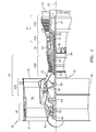
- FIG. 1 is a side cutaway illustration of a geared turbine engine 20, which may be a production turbine engine.
- production may describe a turbine engine being manufactured according to a model specification, which turbine engine is to be delivered ultimately for personal, commercial or government use; e.g., to power a personal, commercial or government aircraft.
- An aircraft production turbine engine for example, may be certified by one or more government and/or non-government organizations (e.g., U.S. Federal Aviation Administration or FAA) for non-test use.
- Such a turbine engine typically is one of a plurality of turbine engines that are manufactured according to the model specification.
- Production turbine engines may have slight variations therebetween as a result of one or more revisions to the model specification, changes in part supplier(s), revised manufacturing techniques, tolerances, etc. Production turbine engines may also be intermittently tested before and/or during use.
- a test turbine engine is a turbine engine which is used strictly for engine testing purposes.
- a test turbine engine may be built for conducting engine tests on a test stand or on a test aircraft in order to obtain necessary data for government certifications of a production turbine engine.
- the turbine engine 20 extends along an axial centerline 22 between an upstream airflow inlet 24 and a downstream airflow exhaust 26.
- the turbine engine 20 includes a fan section 28, a compressor section 29, a combustor section 30 and a turbine section 31.
- the compressor section 29 includes a low pressure compressor (LPC) section 29A and a high pressure compressor (HPC) section 29B.
- the turbine section 31 includes a high pressure turbine (HPT) section 31A and a low pressure turbine (LPT) section 31B.
- the engine sections 28-31 are arranged sequentially along the centerline 22 within an engine housing 32.
- This housing 32 includes an inner case 34 (e.g., a core case) and an outer case 36 (e.g., a fan case).
- the inner case 34 houses the engine sections 29-31; e.g., an engine core.
- the outer case 36 houses the fan section 28 and axially overlaps a forward portion of the inner case 34.
- Each of the engine sections 28, 29A, 29B, 31A and 31B includes a respective rotor 38-42.
- Each of these rotors 38-42 includes a plurality of rotor blades arranged circumferentially around and connected to one or more respective rotor disks.
- the rotor blades may be formed integral with or mechanically fastened, welded, brazed, adhered and/or otherwise attached to the respective rotor disk(s).
- the fan rotor 38 is connected to a gear train 44, for example, through a fan shaft 46.
- the gear train 44 and the LPC rotor 39 are connected to and driven by the LPT rotor 42 through a low speed shaft 47.
- the HPC rotor 40 is connected to and driven by the HPT rotor 41 through a high speed shaft 48.
- the shafts 46-48 are rotatably supported by a plurality of bearings 50; e.g., rolling element and/or thrust bearings. Each of these bearings 50 is connected to the engine housing 32 by at least one stationary structure such as, for example, an annular support strut.
- the air within the core gas path 52 may be referred to as "core air”.
- the air within the bypass gas path 54 may be referred to as "bypass air”.
- the core air is directed through the engine sections 29-31, and exits the turbine engine 20 through the airflow exhaust 26 to provide forward engine thrust.
- fuel is injected into a combustion chamber 56 and mixed with the core air. This fuel-core air mixture is ignited to power the turbine engine 20.
- the bypass air is directed through the bypass gas path 54 and out of the turbine engine 20 through a bypass nozzle 58 to provide additional forward engine thrust.
- at least some of the bypass air may be directed out of the turbine engine 20 through a thrust reverser to provide reverse engine thrust.
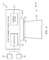
- FIG. 2 illustrates a smart active clearance control (SMACC) system 60 for the turbine engine 20.
- This SMACC system 60 is configured to actively control tip clearance 62 for at least one of the rotors 38-42. More particularly, the SMACC system 60 is configured to control a size (e.g., radial height) of a (e.g., radial) gap between at least one annular shroud 64 and a tip 66 of one or each rotor blade 68 (e.g., a fan, compressor or turbine blade) in at least one stage of the respective rotor 38-42.
- a size e.g., radial height
- a shroud is a segmented or non-segmented abradable blade outer air seal (BOAS), which is disposed radially outboard of and (e.g., axially) aligned with the rotor blades.
- BOAS abradable blade outer air seal
- the SMACC system 60 may reduce leakage between the rotor blades 68 and the shroud 64 and thereby increase turbine engine 20 efficiency.
- the SMACC system 60 is also configured to perform one or more squeeze tests between the rotor blade tips 66 and the shroud 64.
- the term "squeeze test” may describe a test conducted to determine at which point a rotor blade tip (or tips) radially engage and contact (or almost contact) a shroud.
- the SMACC system 60 may adapt (e.g., calibrate and/or recalibrate) its control logic such that optimal tip clearance 62 may be maintained for one or more operating conditions. It is also worth noting, since the SMACC system 60 may adapt its control logic based on the squeeze test(s) performed on that specific turbine engine 20, the adapted control logic may more accurately model tip clearance 62 behavior for that engine 20.
- control logic such as a universal control logic is calibrated based on results of a squeeze test performed on a first engine (e.g., test engine)
- this universal control logic may not accurately model tip clearance behavior of another engine (e.g., a production engine) to which the control logic is applied due to variations between the engines.
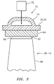
- the SMACC system 60 may include an actuation system 70 for controlling tip clearance 62 as well as performing the squeeze test(s).
- the actuation system 70 may include at least one flow regulator 72 (e.g., a valve, a pump, etc.) and at least one duct 74 fluidly coupled with the flow regulator 72.
- the flow regulator 72 is adapted to regulate flow of fluid, such as air bled or otherwise diverted from the core gas path 52 and/or bypass gas path 54 (see FIG. 1 ), through the duct 74, or some other fluid, including, for example, hydraulic fluid, oil, or fuel.
- the duct 74 is configured to direct the regulated flow of fluid for interaction (e.g., heat exchange) with an apparatus (e.g., the case 34, 36 or another structure) to which the shroud 64 may be attached (mechanically fastened, bonded and/or adhered) or formed integral with. At least a portion of the duct 74, for example, may at least partially circumscribe and/or be configured with the case 34. In this manner, the duct 74 may deliver cooling air to the case 34, which cooling air may actively control thermal expansion / contraction of the case 34 by selectively cooling or heating the case 34.
- an apparatus e.g., the case 34, 36 or another structure
- the shroud 64 may be attached (mechanically fastened, bonded and/or adhered) or formed integral with.
- At least a portion of the duct 74 may at least partially circumscribe and/or be configured with the case 34. In this manner, the duct 74 may deliver cooling air to the case 34, which cooling air may actively control thermal expansion / contraction of the
- the actuation system 70 may control the diameter of the case 34 and, thus, the clearance between the shroud 64 and the rotor blade tips 66.
- Another example of such a system for controlling clearance by regulating temperature of an apparatus to which a shroud is connected is disclosed in U.S. Patent No. 8,434,997 .
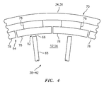
- the actuation system 70 may also or alternatively include one or more actuators 76.
- the actuators 76 are configured to (e.g., radially) displace one or more circumferential segments 78 of the shroud 64. In this manner, the actuators 76 may control the diameter of the shroud 64 and, thus, the clearance 62 between the shroud 64 and the rotor blade tips 66.
- Another example of such a system for controlling clearance by mechanically reconfiguring an apparatus to which a shroud is connected disclosed in U.S. Patent Application Serial No. 13/495,454 .
- the SMACC system 60 of the present disclosure is not limited to the foregoing exemplary actuation system types and configurations.
- the SMACC system 60 also includes a controller 80 for controlling operation of the actuation system 70.
- This controller 80 may be separate from or integrated with one or more other turbine engine controllers and/or aircraft controllers.
- the controller 80 is in signal communication (e.g., hardwired and/or wirelessly coupled) with the actuation system 70.
- the controller 80 may also be in signal communication with one or more other engine sensors 82 and/or other turbine engine components.
- the controller 80 may be implemented with a combination of hardware and software.
- the hardware may include memory and at least one processing device, which may include one or more single-core and/or multi-core processors.
- the hardware may also or alternatively include analog and/or digital circuitry other than that described above.
- the memory is configured to store software (e.g., program instructions and control logics) for execution by the processing device, which software execution may control and/or facilitate performance of one or more operations such as those described in the methods below.
- the memory may be a non-transitory computer readable medium.
- the memory may be configured as or include a volatile memory and/or a nonvolatile memory.
- Examples of a volatile memory may include a random access memory (RAM) such as a dynamic random access memory (DRAM), a static random access memory (SRAM), a synchronous dynamic random access memory (SDRAM), a video random access memory (VRAM), etc.
- RAM random access memory
- DRAM dynamic random access memory
- SRAM static random access memory
- SDRAM synchronous dynamic random access memory
- VRAM video random access memory
- Examples of a nonvolatile memory may include a read only memory (ROM), an electrically erasable programmable read-only memory (EEPROM), a computer hard drive, etc.
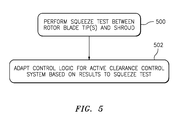
- FIG. 5 is a flow diagram of a method involving a turbine engine such as the turbine engine 20 and, more particularly, a method for configuring and controlling an active clearance control system such as the SMACC system 60.
- the SMACC system 60 performs a squeeze test between the rotor blade tips 66 and the shroud 64. This test may be performed while the turbine engine 20 is configured with a test stand. Alternatively, the squeeze test may be performed while the turbine engine 20 is operating during, for example, aircraft flight and/or normal operation.
- the controller 80 signals the actuation system 70 to reduce the tip clearance 62 to or below zero such that the rotor blade tips 66 and the shroud 64 engage (or almost engage) one another; e.g., the shroud 64 is "squeezed" onto the rotor blade tips 66.
- the controller 80 may determine the rotor blade tips 66 and the shroud 64 are engaging where, for example, there is a decrease in performance of the turbine engine 20.
- a change in turbine engine performance may be measured right before the rotor blade tip(s) 66 engage the shroud 64 and processed to predict when the rotor blade tip(s) 66 will engage the shroud 64.
- Exemplary measures of turbine engine 20 performance include, but are not limited to, thrust output, gas temperature at one or more locations, gas pressure at one or more locations, turbine engine emissions, rotor and/or shaft speed, etc.
- the turbine engine 20 performance may be measured using one or more of the engine sensors 82.
- the SMACC system 60 may also or alternatively include or receive signals from one or more other sensors (e.g., camera(s), laser(s), vibration sensor(s), capacitance probe(s), microwave sensor(s), etc.) that measure other engine parameters and/or directly measure tip clearance 62 through non-contact sensing.
- the foregoing process may also be repeated at different engine operating states (e.g., half power, three-quarters power, full power, etc.) in order to more completely map changes in tip clearance 62.
- the SMACC system 60 adapts its control logic based on the results from the squeeze test.
- the controller 80 may process results from the squeeze test of the step 500 in order to calibrate or recalibrate the control logic; e.g., set or adjust a target tip clearance for one or more points across the power band.
- the SMACC system 60 may apply the results from the squeeze test to (e.g., optimally) adjust a gap between the rotor blade tips 66 and the shroud 64.
- the term "calibrate” may describe a process of setting one or more points, variables and/or terms in the control logic for a first time using data from a first squeeze test.
- the controller 80 may calibrate the control logic based off of results from a squeeze test which is performed for the first time during pre-flight and/or pre-delivery test operation.
- the control logic calibration may actually recalibrate initial settings for the control logic where the initial settings were not derived from a squeeze test performed on that specific engine but rather, for example, another test or certification engine.
- the term "recalibrate” may describe a process of setting one or more points, variables and/or terms in the control logic for a second, third, fourth, etc. time using data from a respective second, third, fourth, etc. squeeze test.
- the controller 80 may recalibrate the control logic based off of results from a squeeze test that is repeated at or after an interval of operation; e.g., a predetermined interval of operating time or flights; before, after and/or during scheduled maintenance; etc.
- Such recalibration may be performed to account for operational wear of the shroud 64, the rotor blades 68, etc. and thereby re-optimize tip clearance 62.
- Such recalibration may be performed one or more times during the life of the turbine engine 20.
- the method of FIG. 5 may be repeated more frequently while the turbine engine 20 is relatively new and less frequently as the turbine engine 20 gets older since more wear generally occurs for newer engines than older engines.
- the adaptation step 502 may be performed to account for shroud 64 and/or rotor blade 68 wear that results from performance of the squeeze test itself.
- the target tip clearance may be adjusted to account for possible wear during the test.
- the controller 80 may signal the flow regulator 72 (e.g., valve) to "leak". This leaking may allow additional fluid to pass through the flow regulator 72 to further cool the case 34, thereby closing clearances between the shroud 64 and rotor blades 68 to account for wear.
- the squeeze test step 500 and the adaptation step 502 may also be individually performed for one or more other turbine engines (see block 604).
- a plurality of production turbine engines may each have its respective control logic calibrated before delivery.
- the SMACC system 60 for each of these production turbine engines may subsequently recalibrate its control logic as desired and/or as necessary.
- the control logic for each of the turbine engines may be initially set as a universal control logic and subsequently recalibrated using the method of FIG. 5 , for example.
- the squeeze test step 500 may be repeated (see block 704) one or more times while the turbine engine 20 is operating at difference operating states; e.g., idle, part throttle, full throttle, etc.
- the results from each of the squeeze test steps 500 may subsequently be processed with one another to adapt the control logic across a portion or substantially the entire flight envelope of the turbine engine 20.
- upstream is used to orientate the components of the turbine engine 20 and the SMACC system 60 described above relative to the turbine engine 20 and its axial centerline 22.
- upstream is used to orientate the components of the turbine engine 20 and the SMACC system 60 described above relative to the turbine engine 20 and its axial centerline 22.
- a person of skill in the art will recognize, however, one or more of these components may be utilized in other orientations than those described above.
- the present invention therefore is not limited to any particular spatial orientations.
- the SMACC system 60 may be included in various turbine engines other than the one described above including industrial turbine engines.
- the SMACC system 60 may be included in a geared turbine engine where a gear train connects one or more shafts to one or more rotors in a fan section, a compressor section and/or any other engine section.
- the SMACC system 60 may be included in a turbine engine configured without a gear train.
- the SMACC system 60 may be included in a geared or non-geared turbine engine configured with a single spool, with two spools (e.g., see FIG. 1 ), or with more than two spools.
- the turbine engine may be configured as a turbofan engine, a turbojet engine, a propfan engine, or any other type of turbine engine. The present invention therefore is not limited to any particular types or configurations of turbine engines.
Landscapes
- Engineering & Computer Science (AREA)
- Mechanical Engineering (AREA)
- General Engineering & Computer Science (AREA)
- Turbine Rotor Nozzle Sealing (AREA)
Abstract
Description
- This disclosure relates generally to active clearance control between a rotor blade and a shroud.
- A turbine engine may include a fan section, a compressor section, a combustor section and a turbine section. Rotor blades in the compressor and the turbine sections may be surrounded by annular shrouds. To reduce leakage between tips of the rotor blades and the shrouds, the turbine engine may include an active clearance control (ACC) system.
- A typical active clearance control system is configured to change a diameter of a base structure to which a shroud is attached and arranged within. By changing the diameter of the base structure, the active clearance control system may change the diameter of the shroud and thereby change clearance between the shroud and the rotor blade tips.
- The active clearance control system may be controlled using a universal control logic. This universal control logic may be derived from tests performed on a test turbine engine, and then applied to the active clearance control systems of all turbine engines of a particular model. Utilizing such a universal control logic, however, cannot account for variations between the turbine engines. For example, slight variations in the components of the active clearance control system and/or of the turbine engines may lead to slightly different engine characteristics. As a result, while the universal control logic may be particularly well suited for one turbine engine (particularly the test turbine engine), the universal control logic may operate another turbine engine with too much clearance and still another turbine engine with too little clearance. Too much and too little clearance may both reduce turbine engine efficiency. Too little clearance may also lead to rubbing and result in premature wear of the shrouds and/or the rotor blades.
- There is a need in the art for improved systems and methods for controlling clearance between a rotor blade tip and a shroud.
- According to an aspect of the invention, a method is provided method for calibrating an active clearance control system for a plurality of turbine engines. The method includes: performing a squeeze test between a tip of a rotor blade and a shroud; and applying results of the squeeze test to adjust a gap between the tip and the shroud. The performing of the squeeze test and the applying of the results is individually performed for each of the turbine engines.
- According to another aspect of the invention, a turbine engine is provided that includes a rotor blade extending to a tip and a shroud radially outboard of the tip. The turbine engine also includes an active clearance control system configured to: perform a squeeze test between the tip and the shroud; and control clearance between the tip and the shroud based on results of the squeeze test. The active clearance control system may also be operable for recalibration based on performance of another squeeze test.
- According to still another aspect of the invention, another turbine engine is provided that includes a rotor blade extending to a tip and a shroud radially outboard of the tip. This production turbine engine also includes a system configured to actively control clearance between the tip and the shroud based on a control logic. The system is further configured to recalibrate the control logic.
- The turbine engine may be a production turbine engine.
- The applying of the results may include, for at least a first of the turbine engines, calibrating and/or recalibrating a control logic for the active clearance control system based on the results of the squeeze test.
- The squeeze test may be performed, for at least a first of the turbine engines, while the first of the turbine engines is configured with a test stand.
- The squeeze test may be performed, for at least a first of the turbine engines, while the first of the turbine engines is operating during aircraft flight.
- The tip and the shroud may radially engage one another during the squeeze test.
- The applying of the results (e.g., calibration or recalibration) may account for wear of the shroud during the squeeze test.
- The squeeze test may be performed, for at least a first of the turbine engines, at or after a predetermined interval of operation of the first of the turbine engines.
- The results may be applied, for at least a first of the turbine engines, to adjust the gap across a flight envelope of the first of the turbine engines.
- The active clearance control system may be configured to perform an additional squeeze test between the tip and the shroud during inflight operation of the turbine engine. The system may also be configured to recalibrate a control logic of the active clearance control system based on results of the additional squeeze test.
- The turbine engine may include an apparatus (e.g., base structure or case) to which the shroud is attached or formed integral with. The active clearance control system may be configured to actively control clearance between the tip and the shroud by regulating temperature of the apparatus. The active clearance control system may also or alternatively be configured to actively control clearance between the tip and the shroud by mechanically reconfiguring the apparatus. The controlling of the clearance based on the results of the squeeze test may account for wear of the shroud during the squeeze test.
- The system may be configured to perform a squeeze test between the tip and the shroud. The recalibration of the control logic may be performed based on the results of the squeeze test.
- The system may be configured to recalibrate the control logic after one or more predetermined intervals of operation of the production turbine engine.
- The foregoing features and the operation of the invention will become more apparent in light of the following description and the accompanying drawings.
-
-
FIG. 1 is a side cutaway illustration of a geared turbine engine, according to an embodiment. -
FIG. 2 is a block diagram of an active clearance control system for controlling clearance between a rotor blade tip and a shroud, according to an embodiment. -
FIG. 3 is a block diagram of an actuator system for changing clearance between a rotor blade tip and a shroud, according to an embodiment. -
FIG. 4 is a block diagram of another actuator system for changing clearance between a rotor blade tip and a shroud, according to an embodiment. -
FIG. 5 is a flow diagram of a method involving an active clearance control system for controlling clearance between a rotor blade tip and a shroud, according to an embodiment. -
FIG. 6 is a flow diagram of another method involving an active clearance control system for controlling clearance between a rotor blade tip and a shroud, according to an embodiment. -
FIG. 7 is a flow diagram of still another method involving an active clearance control system for controlling clearance between a rotor blade tip and a shroud, according to an embodiment. -
FIG. 1 is a side cutaway illustration of a gearedturbine engine 20, which may be a production turbine engine. The term "production" may describe a turbine engine being manufactured according to a model specification, which turbine engine is to be delivered ultimately for personal, commercial or government use; e.g., to power a personal, commercial or government aircraft. An aircraft production turbine engine, for example, may be certified by one or more government and/or non-government organizations (e.g., U.S. Federal Aviation Administration or FAA) for non-test use. Such a turbine engine typically is one of a plurality of turbine engines that are manufactured according to the model specification. Production turbine engines, of course, may have slight variations therebetween as a result of one or more revisions to the model specification, changes in part supplier(s), revised manufacturing techniques, tolerances, etc. Production turbine engines may also be intermittently tested before and/or during use. By contrast, a test turbine engine is a turbine engine which is used strictly for engine testing purposes. For example, a test turbine engine may be built for conducting engine tests on a test stand or on a test aircraft in order to obtain necessary data for government certifications of a production turbine engine. - Referring again to
FIG. 1 , theturbine engine 20 extends along anaxial centerline 22 between anupstream airflow inlet 24 and adownstream airflow exhaust 26. Theturbine engine 20 includes afan section 28, acompressor section 29, acombustor section 30 and aturbine section 31. Thecompressor section 29 includes a low pressure compressor (LPC)section 29A and a high pressure compressor (HPC)section 29B. Theturbine section 31 includes a high pressure turbine (HPT)section 31A and a low pressure turbine (LPT)section 31B. - The engine sections 28-31 are arranged sequentially along the
centerline 22 within anengine housing 32. Thishousing 32 includes an inner case 34 (e.g., a core case) and an outer case 36 (e.g., a fan case). Theinner case 34 houses the engine sections 29-31; e.g., an engine core. Theouter case 36 houses thefan section 28 and axially overlaps a forward portion of theinner case 34. - Each of the
engine sections - The
fan rotor 38 is connected to agear train 44, for example, through afan shaft 46. Thegear train 44 and theLPC rotor 39 are connected to and driven by theLPT rotor 42 through alow speed shaft 47. TheHPC rotor 40 is connected to and driven by theHPT rotor 41 through ahigh speed shaft 48. The shafts 46-48 are rotatably supported by a plurality ofbearings 50; e.g., rolling element and/or thrust bearings. Each of thesebearings 50 is connected to theengine housing 32 by at least one stationary structure such as, for example, an annular support strut. - During operation, air enters the
turbine engine 20 through theairflow inlet 24, and is directed through thefan section 28 and into acore gas path 52 and abypass gas path 54. The air within thecore gas path 52 may be referred to as "core air". The air within thebypass gas path 54 may be referred to as "bypass air". The core air is directed through the engine sections 29-31, and exits theturbine engine 20 through theairflow exhaust 26 to provide forward engine thrust. Within thecombustor section 30, fuel is injected into acombustion chamber 56 and mixed with the core air. This fuel-core air mixture is ignited to power theturbine engine 20. The bypass air is directed through thebypass gas path 54 and out of theturbine engine 20 through abypass nozzle 58 to provide additional forward engine thrust. Alternatively, at least some of the bypass air may be directed out of theturbine engine 20 through a thrust reverser to provide reverse engine thrust. -
FIG. 2 illustrates a smart active clearance control (SMACC)system 60 for theturbine engine 20. ThisSMACC system 60 is configured to actively controltip clearance 62 for at least one of the rotors 38-42. More particularly, theSMACC system 60 is configured to control a size (e.g., radial height) of a (e.g., radial) gap between at least oneannular shroud 64 and atip 66 of one or each rotor blade 68 (e.g., a fan, compressor or turbine blade) in at least one stage of the respective rotor 38-42. An example of a shroud is a segmented or non-segmented abradable blade outer air seal (BOAS), which is disposed radially outboard of and (e.g., axially) aligned with the rotor blades. By actively controlling the tip clearance 62 (e.g., the height of the radial gap), theSMACC system 60 may reduce leakage between therotor blades 68 and theshroud 64 and thereby increaseturbine engine 20 efficiency. - The
SMACC system 60 is also configured to perform one or more squeeze tests between therotor blade tips 66 and theshroud 64. The term "squeeze test" may describe a test conducted to determine at which point a rotor blade tip (or tips) radially engage and contact (or almost contact) a shroud. By processing results of the squeeze test(s), theSMACC system 60 may adapt (e.g., calibrate and/or recalibrate) its control logic such thatoptimal tip clearance 62 may be maintained for one or more operating conditions. It is also worth noting, since theSMACC system 60 may adapt its control logic based on the squeeze test(s) performed on thatspecific turbine engine 20, the adapted control logic may more accurately modeltip clearance 62 behavior for thatengine 20. By contrast, where a control logic such as a universal control logic is calibrated based on results of a squeeze test performed on a first engine (e.g., test engine), this universal control logic may not accurately model tip clearance behavior of another engine (e.g., a production engine) to which the control logic is applied due to variations between the engines. - The
SMACC system 60 may include anactuation system 70 for controllingtip clearance 62 as well as performing the squeeze test(s). Referring toFIG. 3 , theactuation system 70 may include at least one flow regulator 72 (e.g., a valve, a pump, etc.) and at least oneduct 74 fluidly coupled with theflow regulator 72. Theflow regulator 72 is adapted to regulate flow of fluid, such as air bled or otherwise diverted from thecore gas path 52 and/or bypass gas path 54 (seeFIG. 1 ), through theduct 74, or some other fluid, including, for example, hydraulic fluid, oil, or fuel. Theduct 74 is configured to direct the regulated flow of fluid for interaction (e.g., heat exchange) with an apparatus (e.g., thecase shroud 64 may be attached (mechanically fastened, bonded and/or adhered) or formed integral with. At least a portion of theduct 74, for example, may at least partially circumscribe and/or be configured with thecase 34. In this manner, theduct 74 may deliver cooling air to thecase 34, which cooling air may actively control thermal expansion / contraction of thecase 34 by selectively cooling or heating thecase 34. By controlling thermal expansion / contraction of thecase 34, theactuation system 70 may control the diameter of thecase 34 and, thus, the clearance between theshroud 64 and therotor blade tips 66. Another example of such a system for controlling clearance by regulating temperature of an apparatus to which a shroud is connected is disclosed inU.S. Patent No. 8,434,997 . - Referring now to
FIG. 4 , theactuation system 70 may also or alternatively include one ormore actuators 76. Theactuators 76 are configured to (e.g., radially) displace one or morecircumferential segments 78 of theshroud 64. In this manner, theactuators 76 may control the diameter of theshroud 64 and, thus, theclearance 62 between theshroud 64 and therotor blade tips 66. Another example of such a system for controlling clearance by mechanically reconfiguring an apparatus to which a shroud is connected disclosed inU.S. Patent Application Serial No. 13/495,454 . It is worth noting, however, theSMACC system 60 of the present disclosure is not limited to the foregoing exemplary actuation system types and configurations. - Referring again to
FIG. 2 , theSMACC system 60 also includes acontroller 80 for controlling operation of theactuation system 70. Thiscontroller 80 may be separate from or integrated with one or more other turbine engine controllers and/or aircraft controllers. Thecontroller 80 is in signal communication (e.g., hardwired and/or wirelessly coupled) with theactuation system 70. Thecontroller 80 may also be in signal communication with one or moreother engine sensors 82 and/or other turbine engine components. - The
controller 80 may be implemented with a combination of hardware and software. The hardware may include memory and at least one processing device, which may include one or more single-core and/or multi-core processors. The hardware may also or alternatively include analog and/or digital circuitry other than that described above. - The memory is configured to store software (e.g., program instructions and control logics) for execution by the processing device, which software execution may control and/or facilitate performance of one or more operations such as those described in the methods below. The memory may be a non-transitory computer readable medium. For example, the memory may be configured as or include a volatile memory and/or a nonvolatile memory. Examples of a volatile memory may include a random access memory (RAM) such as a dynamic random access memory (DRAM), a static random access memory (SRAM), a synchronous dynamic random access memory (SDRAM), a video random access memory (VRAM), etc. Examples of a nonvolatile memory may include a read only memory (ROM), an electrically erasable programmable read-only memory (EEPROM), a computer hard drive, etc.
-
FIG. 5 is a flow diagram of a method involving a turbine engine such as theturbine engine 20 and, more particularly, a method for configuring and controlling an active clearance control system such as theSMACC system 60. Inblock 500, theSMACC system 60 performs a squeeze test between therotor blade tips 66 and theshroud 64. This test may be performed while theturbine engine 20 is configured with a test stand. Alternatively, the squeeze test may be performed while theturbine engine 20 is operating during, for example, aircraft flight and/or normal operation. - During the squeeze test, the
controller 80 signals theactuation system 70 to reduce thetip clearance 62 to or below zero such that therotor blade tips 66 and theshroud 64 engage (or almost engage) one another; e.g., theshroud 64 is "squeezed" onto therotor blade tips 66. Thecontroller 80 may determine therotor blade tips 66 and theshroud 64 are engaging where, for example, there is a decrease in performance of theturbine engine 20. Alternatively, a change in turbine engine performance may be measured right before the rotor blade tip(s) 66 engage theshroud 64 and processed to predict when the rotor blade tip(s) 66 will engage theshroud 64. Exemplary measures ofturbine engine 20 performance include, but are not limited to, thrust output, gas temperature at one or more locations, gas pressure at one or more locations, turbine engine emissions, rotor and/or shaft speed, etc. Theturbine engine 20 performance may be measured using one or more of theengine sensors 82. TheSMACC system 60 may also or alternatively include or receive signals from one or more other sensors (e.g., camera(s), laser(s), vibration sensor(s), capacitance probe(s), microwave sensor(s), etc.) that measure other engine parameters and/or directly measuretip clearance 62 through non-contact sensing. The foregoing process may also be repeated at different engine operating states (e.g., half power, three-quarters power, full power, etc.) in order to more completely map changes intip clearance 62. - In
block 502, theSMACC system 60 adapts its control logic based on the results from the squeeze test. Thecontroller 80, for example, may process results from the squeeze test of thestep 500 in order to calibrate or recalibrate the control logic; e.g., set or adjust a target tip clearance for one or more points across the power band. In this manner, theSMACC system 60 may apply the results from the squeeze test to (e.g., optimally) adjust a gap between therotor blade tips 66 and theshroud 64. - The term "calibrate" may describe a process of setting one or more points, variables and/or terms in the control logic for a first time using data from a first squeeze test. For example, the
controller 80 may calibrate the control logic based off of results from a squeeze test which is performed for the first time during pre-flight and/or pre-delivery test operation. Note, the control logic calibration may actually recalibrate initial settings for the control logic where the initial settings were not derived from a squeeze test performed on that specific engine but rather, for example, another test or certification engine. - The term "recalibrate" may describe a process of setting one or more points, variables and/or terms in the control logic for a second, third, fourth, etc. time using data from a respective second, third, fourth, etc. squeeze test. For example, the
controller 80 may recalibrate the control logic based off of results from a squeeze test that is repeated at or after an interval of operation; e.g., a predetermined interval of operating time or flights; before, after and/or during scheduled maintenance; etc. Such recalibration may be performed to account for operational wear of theshroud 64, therotor blades 68, etc. and therebyre-optimize tip clearance 62. Such recalibration may be performed one or more times during the life of theturbine engine 20. Furthermore, the method ofFIG. 5 may be repeated more frequently while theturbine engine 20 is relatively new and less frequently as theturbine engine 20 gets older since more wear generally occurs for newer engines than older engines. - In some embodiments, the
adaptation step 502 may be performed to account forshroud 64 and/orrotor blade 68 wear that results from performance of the squeeze test itself. The target tip clearance, for example, may be adjusted to account for possible wear during the test. For example, thecontroller 80 may signal the flow regulator 72 (e.g., valve) to "leak". This leaking may allow additional fluid to pass through theflow regulator 72 to further cool thecase 34, thereby closing clearances between theshroud 64 androtor blades 68 to account for wear. - In some embodiments, referring to
FIG. 6 , thesqueeze test step 500 and theadaptation step 502 may also be individually performed for one or more other turbine engines (see block 604). For example, a plurality of production turbine engines may each have its respective control logic calibrated before delivery. TheSMACC system 60 for each of these production turbine engines may subsequently recalibrate its control logic as desired and/or as necessary. Alternatively, the control logic for each of the turbine engines may be initially set as a universal control logic and subsequently recalibrated using the method ofFIG. 5 , for example. - In some embodiments, referring to
FIG. 7 , thesqueeze test step 500 may be repeated (see block 704) one or more times while theturbine engine 20 is operating at difference operating states; e.g., idle, part throttle, full throttle, etc. The results from each of thesqueeze test steps 500 may subsequently be processed with one another to adapt the control logic across a portion or substantially the entire flight envelope of theturbine engine 20. - The terms "upstream", "downstream", "inner" and "outer" are used to orientate the components of the
turbine engine 20 and theSMACC system 60 described above relative to theturbine engine 20 and itsaxial centerline 22. A person of skill in the art will recognize, however, one or more of these components may be utilized in other orientations than those described above. The present invention therefore is not limited to any particular spatial orientations. - The
SMACC system 60 may be included in various turbine engines other than the one described above including industrial turbine engines. TheSMACC system 60, for example, may be included in a geared turbine engine where a gear train connects one or more shafts to one or more rotors in a fan section, a compressor section and/or any other engine section. Alternatively, theSMACC system 60 may be included in a turbine engine configured without a gear train. TheSMACC system 60 may be included in a geared or non-geared turbine engine configured with a single spool, with two spools (e.g., seeFIG. 1 ), or with more than two spools. The turbine engine may be configured as a turbofan engine, a turbojet engine, a propfan engine, or any other type of turbine engine. The present invention therefore is not limited to any particular types or configurations of turbine engines. - While various embodiments of the present invention have been disclosed, it will be apparent to those of ordinary skill in the art that many more embodiments and implementations are possible within the scope of the invention. For example, the present invention as described herein includes several aspects and embodiments that include particular features. Although these features may be described individually, it is within the scope of the present invention that some or all of these features may be combined with any one of the aspects and remain within the scope of the invention. Accordingly, the present invention is not to be restricted except in light of the attached claims and their equivalents.
Claims (15)
- A method for calibrating an active clearance control system (60) for a plurality of turbine engines (20), the method comprising:performing a squeeze test between a tip (66) of a rotor blade (68) and a shroud (64); andapplying results of the squeeze test to adjust a gap (62) between the tip (66) and the shroud (64);wherein the performing of the squeeze test and the applying of the results is individually performed for each of the turbine engines (20).
- The method of claim 1, wherein the applying of the results comprises, for at least a first of the turbine engines (20), calibrating and/or recalibrating a control logic for the active clearance control system (60) based on the results of the squeeze test.
- The method of claim 1 or 2, wherein the squeeze test is performed, for at least a first of the turbine engines (20), while the first of the turbine engines (20) is configured with a test stand, or operating during aircraft flight.
- The method of claim 1, 2, or 3, wherein the tip (66) and the shroud (64) radially engage one another during the squeeze test.
- The method of any preceding claim, wherein the applying of the results accounts for wear of the shroud (64) during the squeeze test.
- The method of any preceding claim, wherein the squeeze test is performed, for at least a first of the turbine engines (20), after a predetermined interval of operation of the first of the turbine engines (20).
- The method of any preceding claim, wherein the results are applied, for at least a first of the turbine engines (20), to adjust the gap (62) across a flight envelope of the first of the turbine engines (20).
- The method of any preceding claim, wherein at least a first of the turbine engines (20) comprises a production turbine engine.
- A turbine engine, comprising:a rotor blade (68) extending to a tip (66);a shroud (64) radially outboard of the tip (66); andan active clearance control system configured to
perform a squeeze test between the tip (66) and the shroud (64); and
control clearance between the tip (66) and the shroud (64) based on results of the squeeze test;wherein the active clearance control system is operable for recalibration based on performance of another squeeze test. - The turbine engine of claim 9, wherein the active clearance control system is further configured to
perform an additional squeeze test between the tip (66) and the shroud (64) during inflight operation of the turbine engine (20); and
recalibrate a control logic of the active clearance control system based on results of the additional squeeze test. - The turbine engine of claim 9 or 10, further comprising:an apparatus to which the shroud (64) is attached or formed integral with;wherein the active clearance control system is configured to actively control clearance between the tip (66) and the shroud (64) by regulating temperature of the apparatus.
- The turbine engine of claim 9, 10 or 11, further comprising:an apparatus to which the shroud (64) is attached or formed integral with;wherein the active clearance control system is configured to actively control clearance between the tip (66) and the shroud (64) by mechanically reconfiguring the apparatus.
- A turbine engine, comprising:a rotor blade (68) extending to a tip (66);a shroud (64) radially outboard of the tip (66); anda system configured to actively control clearance between the tip (66) and the shroud (64) based on a control logic, the system further configured to recalibrate the control logic.
- The turbine engine of claim 13, wherein the system is configured to recalibrate the control logic after one or more predetermined intervals of operation of the production turbine engine.
- The turbine engine of claim 13 or 14, further comprising:an apparatus to which the shroud (64) is attached or formed integral with; wherein:the system is configured to actively control clearance between the tip (66) and the shroud (64) by regulating temperature of the apparatus; and/orthe system is configured to actively control clearance between the tip (66) and the shroud (64) by mechanically reconfiguring the apparatus.
Applications Claiming Priority (1)
| Application Number | Priority Date | Filing Date | Title |
|---|---|---|---|
| US201462036452P | 2014-08-12 | 2014-08-12 |
Publications (1)
| Publication Number | Publication Date |
|---|---|
| EP2998521A1 true EP2998521A1 (en) | 2016-03-23 |
Family
ID=54010856
Family Applications (1)
| Application Number | Title | Priority Date | Filing Date |
|---|---|---|---|
| EP15180773.2A Withdrawn EP2998521A1 (en) | 2014-08-12 | 2015-08-12 | Smart active clearance control between a rotor blade and shroud |
Country Status (2)
| Country | Link |
|---|---|
| US (1) | US9810091B2 (en) |
| EP (1) | EP2998521A1 (en) |
Families Citing this family (9)
| Publication number | Priority date | Publication date | Assignee | Title |
|---|---|---|---|---|
| US10630541B2 (en) | 2016-07-28 | 2020-04-21 | General Electric Technology Gmbh | Systems and methods for configuration-less process bus with architectural redundancy in digital substations |
| US10612409B2 (en) | 2016-08-18 | 2020-04-07 | United Technologies Corporation | Active clearance control collector to manifold insert |
| US20180073440A1 (en) * | 2016-09-13 | 2018-03-15 | General Electric Company | Controlling turbine shroud clearance for operation protection |
| US10415421B2 (en) * | 2017-02-06 | 2019-09-17 | United Technologies Corporation | Thrust rating dependent active tip clearance control system |
| US10414507B2 (en) * | 2017-03-09 | 2019-09-17 | General Electric Company | Adaptive active clearance control logic |
| US10801359B2 (en) | 2017-03-14 | 2020-10-13 | General Electric Company | Method and system for identifying rub events |
| GB201808352D0 (en) * | 2018-05-22 | 2018-07-11 | Rolls Royce Plc | Air intake system |
| US11156455B2 (en) | 2018-09-26 | 2021-10-26 | General Electric Company | System and method for measuring clearance gaps between rotating and stationary components of a turbomachine |
| US11788426B2 (en) * | 2022-03-04 | 2023-10-17 | General Electric Company | Clearance control for engine performance retention |
Citations (10)
| Publication number | Priority date | Publication date | Assignee | Title |
|---|---|---|---|---|
| US6487491B1 (en) * | 2001-11-21 | 2002-11-26 | United Technologies Corporation | System and method of controlling clearance between turbine engine blades and case based on engine components thermal growth model |
| US20030120415A1 (en) * | 2001-12-21 | 2003-06-26 | General Electric Company Crd | Method and system for controlling distortion of turbine case due to thermal variations |
| US20060140756A1 (en) * | 2004-12-29 | 2006-06-29 | United Technologies Corporation | Gas turbine engine blade tip clearance apparatus and method |
| EP2375004A2 (en) * | 2010-03-31 | 2011-10-12 | General Electric Company | Methods, systems and apparatus relating to tip clearance calculations in turbine engines |
| US8186945B2 (en) * | 2009-05-26 | 2012-05-29 | General Electric Company | System and method for clearance control |
| US20130022442A1 (en) * | 2011-07-18 | 2013-01-24 | General Electric Company | System and method for operating a turbine |
| US8434997B2 (en) | 2007-08-22 | 2013-05-07 | United Technologies Corporation | Gas turbine engine case for clearance control |
| US20130195655A1 (en) * | 2011-09-26 | 2013-08-01 | Flodesign Wind Turbine Corp. | Blade tip to shroud clearance for shrouded fluid turbines |
| US20130323012A1 (en) * | 2012-06-04 | 2013-12-05 | Yuan Dong | Compressor tip clearance management for a gas turbine engine |
| EP2799668A2 (en) * | 2013-04-29 | 2014-11-05 | Rolls-Royce plc | Rotor tip clearance |
Family Cites Families (7)
| Publication number | Priority date | Publication date | Assignee | Title |
|---|---|---|---|---|
| US4513567A (en) | 1981-11-02 | 1985-04-30 | United Technologies Corporation | Gas turbine engine active clearance control |
| US8011883B2 (en) | 2004-12-29 | 2011-09-06 | United Technologies Corporation | Gas turbine engine blade tip clearance apparatus and method |
| US7455495B2 (en) | 2005-08-16 | 2008-11-25 | United Technologies Corporation | Systems and methods for monitoring thermal growth and controlling clearances, and maintaining health of turbo machinery applications |
| US7491029B2 (en) | 2005-10-14 | 2009-02-17 | United Technologies Corporation | Active clearance control system for gas turbine engines |
| US7717671B2 (en) | 2006-10-16 | 2010-05-18 | United Technologies Corporation | Passive air seal clearance control |
| WO2011123106A1 (en) | 2010-03-31 | 2011-10-06 | United Technologies Corporation | Turbine blade tip clearance control |
| US9028205B2 (en) | 2012-06-13 | 2015-05-12 | United Technologies Corporation | Variable blade outer air seal |
-
2015
- 2015-08-11 US US14/823,568 patent/US9810091B2/en active Active
- 2015-08-12 EP EP15180773.2A patent/EP2998521A1/en not_active Withdrawn
Patent Citations (10)
| Publication number | Priority date | Publication date | Assignee | Title |
|---|---|---|---|---|
| US6487491B1 (en) * | 2001-11-21 | 2002-11-26 | United Technologies Corporation | System and method of controlling clearance between turbine engine blades and case based on engine components thermal growth model |
| US20030120415A1 (en) * | 2001-12-21 | 2003-06-26 | General Electric Company Crd | Method and system for controlling distortion of turbine case due to thermal variations |
| US20060140756A1 (en) * | 2004-12-29 | 2006-06-29 | United Technologies Corporation | Gas turbine engine blade tip clearance apparatus and method |
| US8434997B2 (en) | 2007-08-22 | 2013-05-07 | United Technologies Corporation | Gas turbine engine case for clearance control |
| US8186945B2 (en) * | 2009-05-26 | 2012-05-29 | General Electric Company | System and method for clearance control |
| EP2375004A2 (en) * | 2010-03-31 | 2011-10-12 | General Electric Company | Methods, systems and apparatus relating to tip clearance calculations in turbine engines |
| US20130022442A1 (en) * | 2011-07-18 | 2013-01-24 | General Electric Company | System and method for operating a turbine |
| US20130195655A1 (en) * | 2011-09-26 | 2013-08-01 | Flodesign Wind Turbine Corp. | Blade tip to shroud clearance for shrouded fluid turbines |
| US20130323012A1 (en) * | 2012-06-04 | 2013-12-05 | Yuan Dong | Compressor tip clearance management for a gas turbine engine |
| EP2799668A2 (en) * | 2013-04-29 | 2014-11-05 | Rolls-Royce plc | Rotor tip clearance |
Also Published As
| Publication number | Publication date |
|---|---|
| US9810091B2 (en) | 2017-11-07 |
| US20160047269A1 (en) | 2016-02-18 |
Similar Documents
| Publication | Publication Date | Title |
|---|---|---|
| US9810091B2 (en) | Smart active clearance control between a rotor blade and a shroud | |
| US10794286B2 (en) | Method and system for modulated turbine cooling as a function of engine health | |
| US11674407B2 (en) | Systems and methods for controlling blade tip clearances | |
| EP2809918B1 (en) | Gas turbine engine buffer system | |
| EP3358144B1 (en) | Thrust rating dependent active tip clearance control system | |
| EP3196616B1 (en) | Heat flux measurement system | |
| EP3168428B1 (en) | A system and method of calibrating case cooling for a gas turbine engine | |
| US10197007B2 (en) | Method and system for controlling core cowl vent area | |
| US10287986B2 (en) | Gas turbine engine fuel system prognostic algorithm | |
| US20170175750A1 (en) | Method and system for varying tip clearance gap using an actuated shroud | |
| CN114719809B (en) | Method and apparatus for real-time clearance assessment using pressure measurements | |
| EP4119775B1 (en) | Active clearance control system and method for an aircraft engine | |
| US12577884B2 (en) | Rapid active clearance control system of inter stage and mid-seals | |
| US11982189B2 (en) | Warm start control of an active clearance control for a gas turbine engine | |
| EP2971646B1 (en) | Gas turbine engine thermal management system | |
| EP3159492A1 (en) | Cooling passages for gas turbine engine component |
Legal Events
| Date | Code | Title | Description |
|---|---|---|---|
| PUAI | Public reference made under article 153(3) epc to a published international application that has entered the european phase |
Free format text: ORIGINAL CODE: 0009012 |
|
| AK | Designated contracting states |
Kind code of ref document: A1 Designated state(s): AL AT BE BG CH CY CZ DE DK EE ES FI FR GB GR HR HU IE IS IT LI LT LU LV MC MK MT NL NO PL PT RO RS SE SI SK SM TR |
|
| AX | Request for extension of the european patent |
Extension state: BA ME |
|
| RAP1 | Party data changed (applicant data changed or rights of an application transferred) |
Owner name: UNITED TECHNOLOGIES CORPORATION |
|
| 17P | Request for examination filed |
Effective date: 20160923 |
|
| RBV | Designated contracting states (corrected) |
Designated state(s): AL AT BE BG CH CY CZ DE DK EE ES FI FR GB GR HR HU IE IS IT LI LT LU LV MC MK MT NL NO PL PT RO RS SE SI SK SM TR |
|
| STAA | Information on the status of an ep patent application or granted ep patent |
Free format text: STATUS: EXAMINATION IS IN PROGRESS |
|
| 17Q | First examination report despatched |
Effective date: 20200429 |
|
| STAA | Information on the status of an ep patent application or granted ep patent |
Free format text: STATUS: THE APPLICATION IS DEEMED TO BE WITHDRAWN |
|
| RAP1 | Party data changed (applicant data changed or rights of an application transferred) |
Owner name: RAYTHEON TECHNOLOGIES CORPORATION |
|
| 18D | Application deemed to be withdrawn |
Effective date: 20201110 |