EP2998546A1 - Système de moteur et véhicule du type à selle - Google Patents
Système de moteur et véhicule du type à selle Download PDFInfo
- Publication number
- EP2998546A1 EP2998546A1 EP14885069.6A EP14885069A EP2998546A1 EP 2998546 A1 EP2998546 A1 EP 2998546A1 EP 14885069 A EP14885069 A EP 14885069A EP 2998546 A1 EP2998546 A1 EP 2998546A1
- Authority
- EP
- European Patent Office
- Prior art keywords
- fuel
- crankshaft
- intake
- angle
- air mixture
- Prior art date
- Legal status (The legal status is an assumption and is not a legal conclusion. Google has not performed a legal analysis and makes no representation as to the accuracy of the status listed.)
- Withdrawn
Links
Images






Classifications
-
- F—MECHANICAL ENGINEERING; LIGHTING; HEATING; WEAPONS; BLASTING
- F02—COMBUSTION ENGINES; HOT-GAS OR COMBUSTION-PRODUCT ENGINE PLANTS
- F02N—STARTING OF COMBUSTION ENGINES; STARTING AIDS FOR SUCH ENGINES, NOT OTHERWISE PROVIDED FOR
- F02N11/00—Starting of engines by means of electric motors
- F02N11/08—Circuits specially adapted for starting of engines
-
- F—MECHANICAL ENGINEERING; LIGHTING; HEATING; WEAPONS; BLASTING
- F02—COMBUSTION ENGINES; HOT-GAS OR COMBUSTION-PRODUCT ENGINE PLANTS
- F02D—CONTROLLING COMBUSTION ENGINES
- F02D13/00—Controlling the engine output power by varying inlet or exhaust valve operating characteristics, e.g. timing
- F02D13/02—Controlling the engine output power by varying inlet or exhaust valve operating characteristics, e.g. timing during engine operation
- F02D13/0223—Variable control of the intake valves only
- F02D13/0234—Variable control of the intake valves only changing the valve timing only
-
- F—MECHANICAL ENGINEERING; LIGHTING; HEATING; WEAPONS; BLASTING
- F02—COMBUSTION ENGINES; HOT-GAS OR COMBUSTION-PRODUCT ENGINE PLANTS
- F02D—CONTROLLING COMBUSTION ENGINES
- F02D13/00—Controlling the engine output power by varying inlet or exhaust valve operating characteristics, e.g. timing
- F02D13/02—Controlling the engine output power by varying inlet or exhaust valve operating characteristics, e.g. timing during engine operation
- F02D13/0273—Multiple actuations of a valve within an engine cycle
-
- F—MECHANICAL ENGINEERING; LIGHTING; HEATING; WEAPONS; BLASTING
- F02—COMBUSTION ENGINES; HOT-GAS OR COMBUSTION-PRODUCT ENGINE PLANTS
- F02D—CONTROLLING COMBUSTION ENGINES
- F02D29/00—Controlling engines, such controlling being peculiar to the devices driven thereby, the devices being other than parts or accessories essential to engine operation, e.g. controlling of engines by signals external thereto
- F02D29/02—Controlling engines, such controlling being peculiar to the devices driven thereby, the devices being other than parts or accessories essential to engine operation, e.g. controlling of engines by signals external thereto peculiar to engines driving vehicles; peculiar to engines driving variable pitch propellers
-
- F—MECHANICAL ENGINEERING; LIGHTING; HEATING; WEAPONS; BLASTING
- F02—COMBUSTION ENGINES; HOT-GAS OR COMBUSTION-PRODUCT ENGINE PLANTS
- F02D—CONTROLLING COMBUSTION ENGINES
- F02D41/00—Electrical control of supply of combustible mixture or its constituents
- F02D41/009—Electrical control of supply of combustible mixture or its constituents using means for generating position or synchronisation signals
-
- F—MECHANICAL ENGINEERING; LIGHTING; HEATING; WEAPONS; BLASTING
- F02—COMBUSTION ENGINES; HOT-GAS OR COMBUSTION-PRODUCT ENGINE PLANTS
- F02D—CONTROLLING COMBUSTION ENGINES
- F02D41/00—Electrical control of supply of combustible mixture or its constituents
- F02D41/02—Circuit arrangements for generating control signals
- F02D41/04—Introducing corrections for particular operating conditions
- F02D41/06—Introducing corrections for particular operating conditions for engine starting or warming up
- F02D41/062—Introducing corrections for particular operating conditions for engine starting or warming up for starting
-
- F—MECHANICAL ENGINEERING; LIGHTING; HEATING; WEAPONS; BLASTING
- F02—COMBUSTION ENGINES; HOT-GAS OR COMBUSTION-PRODUCT ENGINE PLANTS
- F02N—STARTING OF COMBUSTION ENGINES; STARTING AIDS FOR SUCH ENGINES, NOT OTHERWISE PROVIDED FOR
- F02N19/00—Starting aids for combustion engines, not otherwise provided for
- F02N19/005—Aiding engine start by starting from a predetermined position, e.g. pre-positioning or reverse rotation
-
- F—MECHANICAL ENGINEERING; LIGHTING; HEATING; WEAPONS; BLASTING
- F02—COMBUSTION ENGINES; HOT-GAS OR COMBUSTION-PRODUCT ENGINE PLANTS
- F02P—IGNITION, OTHER THAN COMPRESSION IGNITION, FOR INTERNAL-COMBUSTION ENGINES; TESTING OF IGNITION TIMING IN COMPRESSION-IGNITION ENGINES
- F02P5/00—Advancing or retarding ignition; Control therefor
- F02P5/04—Advancing or retarding ignition; Control therefor automatically, as a function of the working conditions of the engine or vehicle or of the atmospheric conditions
- F02P5/145—Advancing or retarding ignition; Control therefor automatically, as a function of the working conditions of the engine or vehicle or of the atmospheric conditions using electrical means
- F02P5/15—Digital data processing
- F02P5/1502—Digital data processing using one central computing unit
- F02P5/1506—Digital data processing using one central computing unit with particular means during starting
-
- B—PERFORMING OPERATIONS; TRANSPORTING
- B62—LAND VEHICLES FOR TRAVELLING OTHERWISE THAN ON RAILS
- B62K—CYCLES; CYCLE FRAMES; CYCLE STEERING DEVICES; RIDER-OPERATED TERMINAL CONTROLS SPECIALLY ADAPTED FOR CYCLES; CYCLE AXLE SUSPENSIONS; CYCLE SIDECARS, FORECARS, OR THE LIKE
- B62K2202/00—Motorised scooters
-
- F—MECHANICAL ENGINEERING; LIGHTING; HEATING; WEAPONS; BLASTING
- F02—COMBUSTION ENGINES; HOT-GAS OR COMBUSTION-PRODUCT ENGINE PLANTS
- F02D—CONTROLLING COMBUSTION ENGINES
- F02D13/00—Controlling the engine output power by varying inlet or exhaust valve operating characteristics, e.g. timing
- F02D13/02—Controlling the engine output power by varying inlet or exhaust valve operating characteristics, e.g. timing during engine operation
- F02D2013/0292—Controlling the engine output power by varying inlet or exhaust valve operating characteristics, e.g. timing during engine operation in the start-up phase, e.g. for warming-up cold engine or catalyst
-
- F—MECHANICAL ENGINEERING; LIGHTING; HEATING; WEAPONS; BLASTING
- F02—COMBUSTION ENGINES; HOT-GAS OR COMBUSTION-PRODUCT ENGINE PLANTS
- F02D—CONTROLLING COMBUSTION ENGINES
- F02D41/00—Electrical control of supply of combustible mixture or its constituents
- F02D41/0002—Controlling intake air
- F02D2041/001—Controlling intake air for engines with variable valve actuation
-
- F—MECHANICAL ENGINEERING; LIGHTING; HEATING; WEAPONS; BLASTING
- F02—COMBUSTION ENGINES; HOT-GAS OR COMBUSTION-PRODUCT ENGINE PLANTS
- F02D—CONTROLLING COMBUSTION ENGINES
- F02D2250/00—Engine control related to specific problems or objectives
- F02D2250/06—Reverse rotation of engine
-
- F—MECHANICAL ENGINEERING; LIGHTING; HEATING; WEAPONS; BLASTING
- F02—COMBUSTION ENGINES; HOT-GAS OR COMBUSTION-PRODUCT ENGINE PLANTS
- F02N—STARTING OF COMBUSTION ENGINES; STARTING AIDS FOR SUCH ENGINES, NOT OTHERWISE PROVIDED FOR
- F02N19/00—Starting aids for combustion engines, not otherwise provided for
- F02N19/005—Aiding engine start by starting from a predetermined position, e.g. pre-positioning or reverse rotation
- F02N2019/007—Aiding engine start by starting from a predetermined position, e.g. pre-positioning or reverse rotation using inertial reverse rotation
-
- F—MECHANICAL ENGINEERING; LIGHTING; HEATING; WEAPONS; BLASTING
- F02—COMBUSTION ENGINES; HOT-GAS OR COMBUSTION-PRODUCT ENGINE PLANTS
- F02N—STARTING OF COMBUSTION ENGINES; STARTING AIDS FOR SUCH ENGINES, NOT OTHERWISE PROVIDED FOR
- F02N2250/00—Problems related to engine starting or engine's starting apparatus
- F02N2250/04—Reverse rotation of the engine
-
- Y—GENERAL TAGGING OF NEW TECHNOLOGICAL DEVELOPMENTS; GENERAL TAGGING OF CROSS-SECTIONAL TECHNOLOGIES SPANNING OVER SEVERAL SECTIONS OF THE IPC; TECHNICAL SUBJECTS COVERED BY FORMER USPC CROSS-REFERENCE ART COLLECTIONS [XRACs] AND DIGESTS
- Y02—TECHNOLOGIES OR APPLICATIONS FOR MITIGATION OR ADAPTATION AGAINST CLIMATE CHANGE
- Y02T—CLIMATE CHANGE MITIGATION TECHNOLOGIES RELATED TO TRANSPORTATION
- Y02T10/00—Road transport of goods or passengers
- Y02T10/10—Internal combustion engine [ICE] based vehicles
- Y02T10/12—Improving ICE efficiencies
-
- Y—GENERAL TAGGING OF NEW TECHNOLOGICAL DEVELOPMENTS; GENERAL TAGGING OF CROSS-SECTIONAL TECHNOLOGIES SPANNING OVER SEVERAL SECTIONS OF THE IPC; TECHNICAL SUBJECTS COVERED BY FORMER USPC CROSS-REFERENCE ART COLLECTIONS [XRACs] AND DIGESTS
- Y02—TECHNOLOGIES OR APPLICATIONS FOR MITIGATION OR ADAPTATION AGAINST CLIMATE CHANGE
- Y02T—CLIMATE CHANGE MITIGATION TECHNOLOGIES RELATED TO TRANSPORTATION
- Y02T10/00—Road transport of goods or passengers
- Y02T10/10—Internal combustion engine [ICE] based vehicles
- Y02T10/40—Engine management systems
Definitions
- the present invention relates to an engine system and a straddled vehicle including the engine system.
- a large torque is required in order for a crank angle to exceed an angle corresponding to a first compression top dead center when a start-up operation of an engine is performed.
- an intake port is opened in a range of a crank angle corresponding to a normal exhaust stroke (hereinafter referred to as a normal exhaust range) in order to introduce the fuel-air mixture from the intake passage into the combustion chamber.
- a valve driver is configured such that the intake port is opened and an exhaust port is closed in the normal exhaust range during the reverse rotation of the crankshaft. The configuration of the valve driver becomes complicated in this case.
- valve driver is configured such that the exhaust port is opened in the normal exhaust range during both the forward rotation and the reverse rotation of the crankshaft. In this case, however, the intake port and the exhaust port are opened simultaneously in the normal exhaust range during the reverse rotation of the crankshaft.
- An object of the present invention is to provide an engine system and a straddled vehicle in which an engine can be appropriately started.
- the present invention enables an engine to be appropriately started.
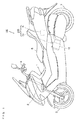
- Fig. 1 is a schematic side view showing the schematic configuration of a motorcycle according to one embodiment of the present invention.
- a front fork 2 is provided at a front of a vehicle body 1 to be swingable to the right and the left.
- a handle 4 is attached to the upper end of the front fork 2, and a front wheel 3 is rotatably attached to the lower end of the front fork 2.
- a seat 5 is provided at substantially the center of the upper portion of the vehicle body 1.
- An ECU (Engine Control Unit) 6 and an engine unit EU are provided below the seat 5.
- the engine unit EU includes, for example, a single-cylinder engine 10.
- the ECU 6 and the engine unit EU constitute an engine system 200.
- a rear wheel 7 is rotatably attached to the lower portion of the rear end of the vehicle body 1. The rotation of the rear wheel 7 is driven by motive power generated by the engine 10.
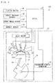
- Fig. 2 is a schematic diagram for explaining the configuration of the engine system 200.
- the engine unit EU includes the engine 10 and an integrated starter generator 14.
- the engine 10 includes a piston 11, a connecting rod 12, a crankshaft 13, an intake valve 15, an exhaust valve 16, a valve driver 17, an ignition plug 18, and an injector 19.
- the piston 11 is provided to be reciprocatable in a cylinder 31 and connected to the crankshaft 13 via the connecting rod 12.
- the reciprocating motion of the piston 11 is converted into the rotational motion of the crankshaft 13.
- the crankshaft 13 is provided with the integrated starter generator 14.
- the integrated starter generator 14 is a generator having a starter motor function, which drives the crankshaft 13 to rotate in forward and reverse directions and generates electric power with the rotation of the crankshaft 13.
- the forward direction is the direction of rotation of a crankshaft 210 during the normal operation of the engine 10, whereas the reverse direction is the opposite direction to the forward direction.
- the integrated starter generator 14 transmits a torque directly to the crankshaft 13 without a reduction gear provided therebetween.
- the rotation of the crankshaft 13 in the forward direction (forward rotation) is transmitted to the rear wheel 7, so that the rotation of the rear wheel 7 is driven.
- a combustion chamber 31 a is formed on the piston 11.
- the combustion chamber 31a communicates with an intake passage 22 through an intake port 21 and communicates with an exhaust passage 24 through an exhaust port 23.
- the intake valve 15 is provided to open and close the intake port 21, and the exhaust valve 16 is provided to open and close the exhaust port 23.
- the intake valve 15 and the exhaust valve 16 are driven by the valve driver 17.
- the intake passage 22 is provided with a throttle valve TV for adjusting the flow rate of air that flows in from outside.
- the ignition plug 18 is configured to ignite a fuel-air mixture in the combustion chamber 31a.
- the injector 19 is configured to inject fuel into the intake passage 22.
- the ECU 6 includes, for example, a CPU (Central Processing Unit) and a memory.
- the CPU and the memory may be replaced with a microcomputer.
- the ECU 6 is electrically connected with a starter switch 41, an intake pressure sensor 42, a crank angle sensor 43, and a current sensor 44.
- the starter switch 41 is provided on the handle 4 of Fig. 1 , for example, to be operated by a driver.
- the intake pressure sensor 42 detects pressure in the intake passage 22.
- the crank angle sensor 43 detects a rotational position of the crankshaft 13 (hereinafter referred to as a crank angle).
- the current sensor 44 detects a current flowing through the integrated starter generator 14 (hereinafter referred to as a motor current).
- An operation of the starter switch 41 is applied as an operation signal to the ECU 6, and the results of detection by the intake pressure sensor 42, the crank angle sensor 43, and the current sensor 44 are applied as detection signals to the ECU 6.
- the ECU 6 controls the integrated starter generator 14, the ignition plug 18 and the injector 19 on the basis of the applied operation and detection signals.
- the engine 10 is started when the starter switch 41 of Fig. 2 is turned on, whereas the engine 10 is stopped when a main switch not shown is turned off. Also, when a predetermined idle stop condition is satisfied, the engine 10 may automatically be stopped. After that, when a predetermined idle stop release condition is satisfied, the engine 10 may be automatically re-started.
- the idle stop condition includes a condition that relates to at least one of, for example, throttle opening (the degree of opening of a throttle valve TV), vehicle speed, and rotation speed of the engine 10.
- the idle stop release condition refers to, for example, the throttle opening being larger than 0 when an accelerator grip is operated.
- a state where the engine 10 is automatically stopped with the idle stop condition being satisfied is hereinafter referred to as an idle stop state.
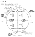
- Fig. 3 is a diagram for explaining the normal operation of the engine unit EU.
- Figs. 4 and 5 are diagrams for explaining the reverse rotation start-up operation of the engine unit EU.
- a top dead center through which the piston 11 passes at the time of shifting from a compression stroke to an expansion stroke is referred to as a compression top dead center
- a top dead center through which the piston 11 passes at the time of shifting from an exhaust stroke to an intake stroke is referred to as an exhaust top dead center
- a bottom dead center through which the piston 11 passes at the time of shifting from the intake stroke to the compression stroke is referred to as an intake bottom dead center
- a bottom dead center through which the piston 11 passes at the time of shifting from the expansion stroke to the exhaust stroke is referred to as an expansion bottom dead center.
- a rotation angle in a range in which the crankshaft 13 makes two rotations (720 degrees) is represented by one circle.
- the two rotations of the crankshaft 13 are equivalent to one cycle of the engine 10.
- the crank angle sensor 43 of Fig. 2 detects a rotational position in a range in which the crankshaft 13 makes one rotation (360 degrees). Based on the pressure in the intake passage 22 detected by the intake pressure sensor 42, the ECU 6 determines which one of the two rotations of the crankshaft 13, equivalent to one cycle of the engine 10, the rotational position detected by the crank angle sensor 43 corresponds to. Thus, the ECU 6 can acquire the rotational position in the range of two rotations (720 degrees) of the crankshaft 13.
- an angle A0 is a crank angle when the piston 11 ( Fig. 2 ) is positioned at the exhaust top dead center
- an angle A2 is a crank angle when the piston 11 is positioned at the compression top dead center
- an angle A1 is a crank angle when the piston 11 is positioned at the intake bottom dead center
- an angle A3 is a crank angle when the piston 11 is positioned at the expansion bottom dead center.
- An arrow R1 indicates a direction in which the crank angle changes during the forward rotation of the crankshaft 13
- an arrow R2 indicates a direction in which the crank angle changes during the reverse rotation of the crankshaft 13.
- Arrows P1 to P4 indicate directions in which the piston 11 moves during the forward rotation of the crankshaft 13.
- Arrows P5 to P8 indicate directions in which the piston 11 moves during the reverse rotation of the crankshaft 13.
- fuel is injected into the intake passage 22 ( Fig. 2 ) by the injector 19 ( Fig. 2 ).
- the angle A11 is positioned at a further advanced angle than the angle A0 in the forward direction.
- the intake port 21 ( Fig. 2 ) is subsequently opened by the intake valve 15 ( Fig. 2 ) in the range from an angle A12 to an angle A13.
- the angle A12 is positioned at a further retarded angle than the angle A11 and at a further advanced angle than the angle A0
- the angle A13 is positioned at a further retarded angle than the angle A1 in the forward direction.
- the range from the angle A12 to the angle A13 is an example of a normal intake range. This allows a fuel-air mixture including air and fuel to be introduced into the combustion chamber 31 a ( Fig. 2 ) through the intake port 21.
- the fuel-air mixture in the combustion chamber 31a ( Fig. 2 ) is ignited by the ignition plug 18 ( Fig. 2 ).
- the angle A14 is positioned at a further advanced angle than the angle A2 in the forward direction.
- the ignited fuel-air mixture causes explosion (combustion of the fuel-air mixture) in the combustion chamber 31a.
- Energy generated by the combustion of the fuel-air mixture turns to a driving force of the piston 11.
- the exhaust port 23 ( Fig. 2 ) is opened by the exhaust valve 16 ( Fig. 2 ) in the range from an angle A15 to an angle A16.
- the angle A15 is positioned at a further advanced angle than the angle A3, and the angle A16 is positioned at a further retarded angle than the angle A0 in the forward direction.
- the range from the angle A15 to the angle A16 is an example of the normal intake range. This allows the combusted air to be exhausted from the combustion chamber 31a through the exhaust port 23.
- the reverse rotation start-up operation of the engine unit EU will be described with reference to Figs. 4 and 5 .
- the crankshaft 13 is rotated forward after it is rotated reversely.
- the reverse rotation of the crankshaft 13 causes the fuel-air mixture to be compressed and then ignited in the combustion chamber 31 a, and also the crankshaft 13 is rotated forward.
- a torque of the crankshaft 13 in the forward direction is sufficiently increased with the energy generated by the combustion. Accordingly, the crank angle exceeds the angle A2 corresponding to the first compression top dead center.
- the reverse rotation star-up operation is repeated until the fuel-air mixture is successfully combusted.
- the successful combustion of the fuel-air mixture means that the fuel-air mixture is appropriately combusted by ignition.
- the reverse rotation start-up operation will be described in detail below.
- the crank angle is adjusted in a predetermined reverse rotation starting range before a first reverse rotation start-up operation is performed.
- the reverse rotation staring range is, for example, in a range from the angle A0 to the angle A2 in the forward direction and preferably in a range from the angle A13 to the angle A2.
- the reverse rotation starting range is a range from an angle A30a to an angle A30b.
- the angular range A30a, A30b is in a range from the angular range A13 to the angle A2.
- the crankshaft 13 is rotated in the reverse direction from a state where the crank angle is in the reverse rotation staring range. Then, the crank angle changes in the direction of the arrow R2.
- the piston 11 is lowered in a range from the angle A2 to the angle A1, raised in a range from the angle A1 to the angle A0, lowered in a range from the angle A0 to the angle A3, and raised in a range from the angle A3 to the angle A2.
- the moving direction of the piston 11 during the reverse rotation of the crankshaft 13 is opposite to the moving direction of the piston 11 during the forward rotation of the crankshaft 13.
- the fuel is injected into the intake passage 22 ( Fig. 2 ) by the injector 19 ( Fig. 2 ).
- the angle A23 is positioned at a further advanced angle than the angle A0.
- the amount of injection of the fuel at the angle A23 in the first reverse rotation start-up operation differs from the amount of injection of the fuel at the angle A23 in a second and subsequent reverse rotation start-up operations.
- the intake port 21 ( Fig. 2 ) is opened by the intake valve 15 ( Fig. 2 ).
- the range from the angle A21 to the angle A22 is an example of a start-up intake range.
- the angles A21, A22 are in the range from the angle A0 to the angle A3. In this case, since the piston 11 is raised in the range from the angle A1 to the angle A0, air or fuel is hardly introduced into the combustion chamber 31a in the range from the angle A13 to the angle A12.
- the exhaust port 23 ( Fig. 2 ) is opened by the exhaust valve 16 ( Fig. 2 ).
- gas is led to the combustion chamber 31 a from the exhaust passage 24.
- an uncombusted fuel-air mixture staying in the exhaust passage 24 is led into the combustion chamber 31 a in the second and subsequent reverse rotation staring operations.
- Energization of an ignition coil connected to the ignition plug 18 ( Fig. 2 ) is started at an angle 31 a, and the fuel-air mixture in the combustion chamber 31 a is ignited by the ignition plug 18 ( Fig. 2 ) at an angle 31a.
- the angle A31a is positioned at a further advanced angle than the angle A31, and the angle A31 is positioned at a further advanced angle than the angle A2.
- the angle A31 is an example of a start-up ignition range.
- the fuel-air mixture is ignited, and the crankshaft 13 is rotated in the forward direction.
- the crank angle is changed in the direction of the arrow R1.
- the exhaust port 23 ( Fig. 2 ) is opened by the exhaust valve 16 ( Fig. 2 ) in a range from an angle A15 to an angle A16. If the fuel-air mixture is successfully combusted right before this opening of the exhaust port 23, then the combusted gas is led to the exhaust passage 24 from the combustion chamber 31a. On the other hand, if the fuel-air mixture is not successfully combusted, then the uncombusted fuel-air mixture is led to the exhaust passage 24 from the combustion chamber 31 a.
- the fuel is injected into the intake passage 22 ( Fig. 2 ) by the injector 19 ( Fig. 2 ) at the angle A11, and the intake port 21 ( Fig. 2 ) is opened by the intake valve 15 ( Fig. 2 ) in the range from the angle A12 to the angle A13.
- the fuel-air mixture is introduced from the intake passage 22 into the combustion chamber 31a.
- the amount of injection of the fuel at the angle A11 in the reverse rotation start-up operation varies depending on the result of determination as to whether the fuel-air mixture has been successfully combusted.
- a combustion determination as to whether the fuel-air mixture has been successfully combusted is performed after the ignition at the angle A31 and before the crank angle reaches the angle A2 corresponding to the first compression top dead center.
- a first combustion determination is performed at an angle A32
- a second combustion determination is performed at an angle A33.
- a point of time at which the crank angle reaches the angle A33 is an example of a first point of time
- a point of time at which the crank angle reaches the angle A32 is an example of a second point of time.
- the angle A32 is positioned at a further advanced angle than the angle A15
- the angle A33 is positioned at a further retarded angle than the angle A13.
- the first combustion determination it is determined based on a result of detection by the crank angle sensor 43 ( Fig. 2 ) whether the rotation state of the crankshaft 13 satisfies a predetermined first condition.
- the second combustion determination it is determined based on a result of detection by the crank angle sensor 43 ( Fig. 2 ) whether the rotation state of the crankshaft 13 satisfies a predetermined second condition.
- the rotation state of the crankshaft 13 is, for example, a rotational speed of the crankshaft 13 or a rate of change of the rotational speed (rotational acceleration) of the crankshaft 13.
- Each of the first and second conditions is, for example, that the rotational speed or the rotational acceleration of the crankshaft 13 is higher than a predetermined threshold value.
- the threshold value of the first condition and that of the second condition are different from each other. Accordingly, it can be accurately determined whether the fuel-air mixture has been appropriately combusted.
- the determination as to whether the fuel-air mixture has been successfully combusted is not limited to the above-mentioned example.
- the second combustion determination is performed at a point of time at which the crank angle is close to the angle A2 corresponding to the compression top dead center.
- the determination as to whether the fuel-air mixture has been successfully combusted may be performed in consideration of both the rotational speed of the crankshaft 13 at the time of the first combustion determination and the rotational speed of the crankshaft 13 at the time of the second combustion determination. For instance, when an average value of the rotational speed of the crankshaft 13 at the time of the first combustion determination and the rotational speed of the crankshaft 13 at the time of the second combustion determination is higher than a predetermined value, it may be determined that the fuel-air mixture has been successfully combusted.
- the determination as to whether the fuel-air mixture has been successfully combusted may be performed in consideration of both the rotational acceleration of the crankshaft 13 at the time of the first combustion determination and the rotational acceleration of the crankshaft 13 at the time of the second combustion determination.
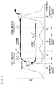
- Figs. 6 and 7 are schematic diagrams for explaining the first and second combustion determinations and the repetition of the reverse rotation start-up operation.
- Figs. 6 and 7 show, for reference, a relationship between the crank angle and a rotational load of the crankshaft 13.
- the abscissa represents the crank angle
- the ordinate represents the rotational load of the crankshaft 13.
- the rotational load of the crankshaft 13 is the largest at the angle A2 corresponding to the compression top dead center. Also, in the examples of Figs. 6 and 7 , a load for driving the intake valve 15 is applied to the crankshaft 13 at an intermediate position between the angle A1 and the angle A0, so that the rotational load of the crankshaft 13 is increased. Further, a load for driving the exhaust valve 16 is applied to the crankshaft 13 at an intermediate position between the angle A0 and the angle A3, so that the rotational load of the crankshaft 13 is increased.
- the fuel is injected at the angle A23 while the crankshaft 13 is rotated in the reverse direction.
- the amount of injection of the fuel at the angle A23 is set to V1.
- the amount V1 is an example of a third amount.
- the fuel-air mixture is successfully combusted.
- the fuel-air mixture is appropriately combusted, and the crankshaft 13 is driven in the forward direction.
- the first condition is satisfied in the first combustion determination at the angle A32.
- the amount of injection of fuel at the angle A11 is set to V2.
- the amount V2 is an amount that is prepared for ignition at the angle A14 in the normal operation.
- the amount V2 is an example of a second amount.
- the second condition is satisfied in the second combustion determination at the angle A33.
- the engine unit EU is shifted to the normal operation without the repetition of the reverse rotation start-up operation. More specifically, the crank angle exceeds the angle A2 which corresponds to the compression top dead center, and the fuel-air mixture is ignited at the angle A14.
- the fuel-air mixture is not successfully combusted by the ignition at the angle A31 in the first reverse rotation start-up operation.
- the first condition is not satisfied in the first combustion determination at the angle A32.
- the amount of injection of fuel is set to V2a at the angle A11.
- the amount V2a is an amount that is prepared for ignition in a subsequent reverse rotation start-up operation and is smaller than the amount V2 set in the example of Fig. 6 .
- the amount V2a is an example of a first amount. In this case, the fuel is prevented from being wastefully consumed.
- the amount of injection of the fuel at the angle A23 during the reverse rotation is set to V1 a.
- the amount V1a is an example of a fourth amount and is smaller than the amount V1 set in the first reverse rotation start-up operation. In this case, the fuel is prevented from being wastefully consumed.
- the fuel-air mixture is successfully combusted by the ignition at the angle A31 in the second reverse rotation start-up operation.
- the fuel-air mixture is appropriately combusted, and the crankshaft 13 is driven in the forward direction. Therefore, the first condition is satisfied in the first combustion determination at the angle A32.
- the amount of injection of the fuel at the angle A11 is set to V2.
- the second condition is satisfied in the second combustion determination at the angle A33. Accordingly, the engine unit EU is shifted to the normal operation without the repetition of the reverse rotation start-up operation.
- Figs. 8 and 9 are diagrams for explaining effects caused by the repetition of the reverse rotation start-up operation.
- the injected fuel vaporizes in the intake passage 22, so that a fuel-air mixture is produced.
- the temperature of the engine 10 is high, the fuel is likely to vaporize, so that the fuel-air mixture is likely to be produced.
- the temperature of the engine 10 is low, the fuel is unlikely to vaporize, so that the fuel-air mixture is unlikely to be produced.
- the temperature of the engine 10 is high right after the engine 10 is stopped, and when a long period of time has elapsed after the stop of the engine 10, the temperature of the engine 10 is reduced. Therefore, during re-start from the idle stop state, for example, the fuel is likely to vaporize, so that the fuel-air mixture is likely to be produced.
- the fuel is unlikely to vaporize, so that the fuel-air mixture is unlikely to be produced.
- the fuel-air mixture is introduced from the intake passage 22 into the combustion chamber 31a through the intake port 21 in the range from the angle A21 to the angle A22.
- the exhaust port 23 is opened, so that gas is introduced also into the combustion chamber 31a from the exhaust port 23.
- a flow velocity of gas from the intake passage 22 to the combustion chamber 31a is lower as compared to a case in which only the intake port 21 is opened.
- part of the fuel-air mixture in the intake passage 22 may remain in the intake passage 22 without being introduced into the combustion chamber 31 a.
- part of the fuel which has not vaporized in the intake passage 22 is moved to the combustion chamber 31a by a flow of gas passing through the intake passage 22.
- the fuel is atomized (reduced in particle size), so that fuel-air mixture concentration is increased.
- the fuel-air mixture concentration means the concentration of the fuel in the fuel-air mixture.
- the flow velocity of the gas passing through the intake passage 22 is low in the range from the angle A21 to the angle A22, so that the fuel is unlikely to be atomized.
- the fuel-air mixture in the reverse rotation start-up operation, is unlikely to be sufficiently introduced into the combustion chamber 31a from the intake passage 22, and unvaporized fuel is unlikely to be atomized. Further, during the cold start-up, the fuel-air mixture is unlikely to be produced in the intake passage 22. Therefore, in the first reverse rotation start-up operation, the fuel-air mixture concentration in the combustion chamber 31 a is likely to be lower than an appropriate value. As a result, as shown in Fig. 8(c) , it is likely that the fuel-air mixture is not successfully combusted by the ignition at the angle A31.
- the uncombusted fuel-air mixture in the combustion chamber 31a is led to the exhaust passage 24 through the exhaust port 23 in the range from the angle A15 to the angle A16 while the crankshaft 13 is rotated in the forward direction.
- the flow velocity of the gas passing through the exhaust passage 24 is low. Therefore, a large part of the fuel-air mixture led to the exhaust passage 24 remains in the exhaust passage 24 without being exhausted to the outside.
- the unvaporized fuel is also moved to the exhaust passage 24 from the combustion chamber 31 a together with the fuel-air mixture. Further, at the angle A11 in the range from the angle A15 to the angle A16, the fuel is injected into the intake passage 22.
- the fuel-air mixture is introduced into the combustion chamber 31 a through the intake port 21 in the range from the angle A12 to the angle A13.
- the intake port 21 is opened except for a range from the angle A12 to the angle A16 ( Fig. 5 ) (overlap). Therefore, the flow velocity of the gas from the intake passage 22 to the combustion chamber 31a is relatively high.
- the fuel-air mixture in the intake passage 22 is efficiently introduced into the combustion chamber 31a, and the fuel is likely to be atomized by the flow of the gas passing through the intake passage 22. Thereafter, the rotation direction of the crankshaft 13 is switched to the reverse direction.
- the second reverse rotation start-up operation will be described.
- the fuel is injected into the intake passage 22 at the angle A23 while the crankshaft 13 is rotated in the reverse direction.
- the fuel-air mixture is introduced into the combustion chamber 31a from the intake passage 22 through the intake port 21 in the range from the angle A21 to the angle A22.
- the fuel-air mixture which remains in the exhaust passage 24, is introduced into the combustion chamber 31a through the exhaust port 23.
- the fuel-air mixture in the combustion chamber 31a includes each of the fuel injected at the angle A23 in the first reverse rotation start-up operation ( Fig. 8(a) ), the fuel injected at the angle A11 in the first reverse rotation start-up operation ( Fig. 8(d) ), and the fuel injected at the angle A23 in the second reverse rotation start-up operation ( Fig. 9(b) ). In this manner, the reverse rotation start-up operation is repeated, so that the fuel in the combustion chamber 31 a is accumulated.
- the unvaporized fuel is introduced into the combustion chamber 31 a from the intake passage 22 and the exhaust passage 24.
- the unvaporized fuel flows in the intake passage 22, the combustion chamber 31 a and the exhaust passage 24, thereby being gradually atomized. Therefore, the reverse rotation start-up operation is repeated, so that atomization of the fuel is progressed. Further, the temperature of the engine 10 is increased by the repetition of the reverse rotation start-up operation, so that the fuel is likely to vaporize.
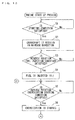
- the ECU 6 performs the engine start-up process based on a control program that is stored in advance in the memory.
- Figs. 10 to 12 are flow charts of the engine start-up process.
- the engine start-up process is performed when a main switch (not shown) is turned on, or when the engine 10 is shifted to the idle stop state.
- the ECU 6 determines whether a predetermined starting condition is satisfied (step S1).
- the starting condition is that the starter switch 41 ( Fig. 2 ) is turned on, for example.
- the starting condition is that an idle stop release condition is satisfied.
- step S2 the ECU 6 repeats the process of step S1 until the starting condition is satisfied.
- the ECU 6 controls the integrated starter generator 14 such that the crankshaft 13 is rotated in the reverse direction (step S2).
- the crank angle when the crank angle is not in the reverse rotation starting range (the range from the angle A30a to A30b), the crank angle may be adjusted in the reverse rotation starting range before the crankshaft 13 is rotated in the reverse direction as described above.
- the ECU 6 determines whether a reverse rotation fuel injection condition is satisfied (step S3).
- the reverse rotation fuel injection condition is that the crank angle acquired from results of detection by the intake pressure sensor 42 ( Fig. 2 ) and the crank angle sensor 43 ( Fig. 2 ) reaches the angle A23 of Fig. 4 .
- the ECU 6 repeats the process of step S3.
- the ECU 6 controls the injector 19 ( Fig. 2 ) such that the fuel is injected into the intake passage 22 ( Fig. 2 ) (step S4). In this case, the amount of injection of the fuel is set to V1.
- the ECU 6 determines whether a reverse rotation energization starting condition is satisfied (step S5).
- the reverse rotation energization starting condition is that the crank angle acquired from the results of detection by the intake pressure sensor 42 ( Fig. 2 ) and the crank angle sensor 43 ( Fig. 2 ) reaches the angle A31a of Fig. 4 .
- the ECU 6 repeats the process of step S5.
- the ECU 6 starts the energization to the ignition coil (step S6).
- the ECU 6 determines whether a reverse rotation ignition condition is satisfied (step S7).
- the reverse rotation ignition condition is that a motor current acquired from a result of detection by the current sensor 44 ( Fig. 2 ) reaches a predetermined threshold value.
- the motor current is increased as the crank angle becomes closer to the angle A2 of Fig. 4 .
- the motor current reaches the threshold value.
- step S7 When the reverse rotation ignition condition is not satisfied, the ECU 6 repeats the process of step S7.
- the ECU 6 controls the integrated starter generator 14 such that the crankshaft 13 is rotated in the forward direction (step S8), and controls the ignition plug 18 such that the fuel-air mixture in the combustion chamber 31 a is ignited (step S9).
- the ECU 6 determines whether a first combustion determination condition is satisfied (step S10).
- the first combustion determination condition is that the crank angle acquired from the results of detection of the intake pressure sensor 42 ( Fig. 2 ) and the crank angle sensor 43 ( Fig. 2 ) reaches the angle A32 of Fig. 5 .
- the ECU 6 repeats the process of step S10.
- the ECU 6 makes the first combustion determination (step S11).
- the ECU 6 determines whether a forward rotation fuel injection condition is satisfied (step S12).
- the forward rotation fuel injection condition is that the crank angle acquired from the results of detection of the intake pressure sensor 42 ( Fig. 2 ) and the crank angle sensor 43 ( Fig. 2 ) reaches the angle A11 of Fig. 5 .
- the ECU 6 repeats the process of step S12.
- the ECU 6 controls the injector 19 ( Fig. 2 ) such that the fuel is injected into the intake passage 22 ( Fig. 2 ) (step S13).
- an amount of injection of the fuel is set based on the result of the first combustion determination in step S11. As described above, when the first condition is satisfied in the first combustion determination, the amount of injection of the fuel is set to V2. On the other hand, when the first condition is not satisfied in the first combustion determination, the amount of injection of the fuel is set to V2a that is smaller than V2.
- the ECU 6 determines whether a second combustion determination condition is satisfied (step S14).
- the second combustion determination condition is that the crank angle acquired from the results of detection of the intake pressure sensor 42 ( Fig. 2 ) and the crank angle sensor 43 ( Fig. 2 ) reaches the angle A33 of Fig. 5 .
- the ECU 6 repeats the process of step S14.
- the ECU 6 makes the second combustion determination (step S15).
- the ECU 6 determines whether the fuel-air mixture is successfully combusted by the ignition in step S9 of Fig. 11 based on the results of the first combustion determination in step S11 of Fig. 11 and the second combustion determination in step S14 of Fig. 12 (step S16).
- the ECU 6 terminates the engine start-up process.
- the crank angle exceeds the angle corresponding to the first compression top dead center by the energy generated by the combustion of the fuel-air mixture, and the engine unit EU is shifted to the normal operation of Fig. 3 .
- step S18 determines whether the reverse rotation fuel injection condition is satisfied.
- the reverse rotation fuel injection condition is the same as that in step S3 of Fig. 10 .
- the ECU 6 repeats the process of step S18.
- the ECU 6 controls the injector 19 ( Fig. 2 ) such that the fuel is injected into the intake passage 22 ( Fig. 2 ) (step S19).
- the amount of injection of the fuel is set to V1 a that is smaller than the amount of injection V1 in step S4.
- the ECU 6 returns to the process of step S5.
- the reverse rotation start-up operation is repeated.
- the first and second combustion determinations are performed after the ignition of the fuel-air mixture in the reverse rotation start-up operation, and the reverse rotation start-up operation is repeated when it is determined that the fuel-air mixture is not successfully combusted.
- the fuel flows in the intake passage 22, the exhaust passage 24 and the combustion chamber 31 a together with the gas (fuel-air mixture). This promotes atomization of the fuel and thus gradually increases the fuel-air mixture concentration. Accordingly, the fuel-air mixture can be finally appropriately combusted. Therefore, the crankshaft 13 can be rotated such that the crank angle exceeds the angle corresponding to the first compression top dead center. As a result, the engine 10 can be appropriately started.
- the exhaust port 23 is opened.
- the exhaust port 23 is opened in the same crank angle range during both the forward and reverse rotations of the crankshaft 13. This reduces the tendency of complexity of the configuration of the valve driver 17.
- the first combustion determination is performed at the angle A32 before the crank angle reaches the normal intake range
- the second combustion determination is performed at the angle A33 after the crank angle has passed the normal intake range.
- the combustion determination is performed in a step- by-step manner, so that it can be appropriately determined whether the fuel-air mixture is successfully combusted.
- the engine 10 can be appropriately started.
- the amount of injection at the combustion at the angle A11 is adjusted based on the result of the first combustion determination.
- respective suitable amounts of the fuel for the ignition in the normal operation and the ignition in the subsequent reverse rotation start-up operation can be injected. Therefore, the fuel-air mixture having respective suitable concentration can be introduced into the combustion chamber 31 a.
- the amount of injection of the fuel at the angle A23 in the first reverse rotation start-up operation is different from the amount of injection of the fuel at the angle A23 in the second and subsequent reverse rotation start-up operations.
- the fuel-air mixture concentration in the combustion chamber 31a can be gradually increased while the fuel is prevented from being wastefully consumed.
- Fig. 13 is a schematic diagram for explaining another example of the reverse rotation start-up operation.
- the fuel-air mixture is not successfully combusted by the ignition at the angle A31 in the first reverse rotation start-up operation.
- the first condition is not satisfied in the first combustion determination.
- no fuel is injected at the angle A11 right thereafter.
- no fuel is injected at the angle A23 during the reverse rotation of the crankshaft 13 in the second reverse rotation start-up operation.
- the fuel-air mixture is successfully combusted by the ignition at the angle A31, so that the first condition is satisfied in the first combustion determination.
- the fuel is injected at the angle A11 after the first combustion determination.
- the present invention is not limited to this.
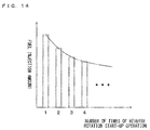
- Fig. 14 is a diagram for explaining other examples of the amount of injection of the fuel.
- the abscissa indicates the number of times of the reverse rotation start-up operation
- the ordinate indicates the amount of injection of the fuel at the angle A23.
- the reverse rotation start-up operation is repeated, so that the fuel-air mixture concentration in the combustion chamber 31 a is gradually increased.
- the amount of injection of the fuel is adjusted to be gradually reduced as the number of times of the reverse rotation start-up operation is increased. Accordingly, the fuel is prevented from being wastefully consumed, and the fuel-air mixture concentration in the combustion chamber 31a is prevented from being excessively high.
- the amount of injection of the fuel at the angle A11 when the fuel-air mixture is not successfully combusted in the reverse rotation start-up operation may also be adjusted to be gradually reduced as the number of times of the reverse rotation start-up operation is increased similarly to the example of Fig. 14 .
- the present invention is not limited to this. Only one of the first and second combustion determinations may be performed. Further, the number of times of the combustion determination to be performed, and the crank angle at which the combustion determination is performed, are not limited to the above-mentioned example, but can be suitably changed. For example, the combustion determination based on the rotation state of the crankshaft may be continuously performed in the range from the angle A32 to the angle A33, and it may be determined whether the fuel-air mixture is successfully combusted.
- the amount of injection of the fuel at the angle A11 is adjusted based on the results of the first and second combustion determinations in the above-mentioned embodiment, the amount of injection of the fuel at the angle A11 may be constant regardless of the results of the first and second combustion determinations. Further, while the amount of injection of the fuel at the angle A23 is adjusted based on the number of times of the repetition of the reverse rotation start-up operation in the above-mentioned embodiment, the amount of injection of the fuel at the angle A23 may be constant regardless of the number of times of the repetition of the reverse rotation start-up operation.
- the intake port 21 is opened in the range from the angle A13 to the angle A12 during the reverse rotation of the crankshaft 13 in the above-mentioned embodiment, the intake port 21 does not have to be opened in this range.
- the present invention is not limited to this.
- the present invention may be applied to another straddled vehicle such as a motor tricycle, an ATV (All-Terrain Vehicle) or the like.
- the engine unit EU is an example of an engine unit
- the engine 10 is an example of an engine
- the integrated starter generator 14 is an example of an integrated starter generator
- the ECU 6 is an example of a controller
- the injector 19 is an example of a fuel injection device
- the ignition plug 18 is an example of an ignition device
- the valve driver 17 is an example of a valve driver
- the intake valve 15 is an example of an intake valve
- the exhaust valve 16 is an example of an exhaust valve
- the crank angle sensor 43 is an example of a rotation state detector
- the crankshaft 13 is an example of a crankshaft.
- the first and second conditions are examples of a start-up condition
- the first condition is an example of a start-up preparation condition.
- the motorcycle 100 is an example of a straddled vehicle
- the rear wheel 7 is an example of a drive wheel
- the vehicle body 1 is an example of a main body.
- the present invention is applicable to various types of engine systems and straddled vehicles.
Landscapes
- Engineering & Computer Science (AREA)
- Chemical & Material Sciences (AREA)
- Combustion & Propulsion (AREA)
- Mechanical Engineering (AREA)
- General Engineering & Computer Science (AREA)
- Theoretical Computer Science (AREA)
- Signal Processing (AREA)
- Combined Controls Of Internal Combustion Engines (AREA)
- Electrical Control Of Air Or Fuel Supplied To Internal-Combustion Engine (AREA)
- Output Control And Ontrol Of Special Type Engine (AREA)
Applications Claiming Priority (1)
| Application Number | Priority Date | Filing Date | Title |
|---|---|---|---|
| PCT/JP2014/003882 WO2016013046A1 (fr) | 2014-07-23 | 2014-07-23 | Système de moteur et véhicule du type à selle |
Publications (2)
| Publication Number | Publication Date |
|---|---|
| EP2998546A1 true EP2998546A1 (fr) | 2016-03-23 |
| EP2998546A4 EP2998546A4 (fr) | 2018-02-14 |
Family
ID=55162605
Family Applications (1)
| Application Number | Title | Priority Date | Filing Date |
|---|---|---|---|
| EP14885069.6A Withdrawn EP2998546A4 (fr) | 2014-07-23 | 2014-07-23 | Système de moteur et véhicule du type à selle |
Country Status (3)
| Country | Link |
|---|---|
| EP (1) | EP2998546A4 (fr) |
| TW (1) | TWI544140B (fr) |
| WO (1) | WO2016013046A1 (fr) |
Cited By (2)
| Publication number | Priority date | Publication date | Assignee | Title |
|---|---|---|---|---|
| CN110425071A (zh) * | 2019-07-19 | 2019-11-08 | 重庆巩诚投资有限公司 | 发动机起动控制方法 |
| US11703005B2 (en) | 2020-01-20 | 2023-07-18 | Brp-Rotax Gmbh & Co. Kg | Cranking procedure for a four-stroke internal combustion engine with a crankshaft mounted electric turning machine |
Families Citing this family (1)
| Publication number | Priority date | Publication date | Assignee | Title |
|---|---|---|---|---|
| WO2017188144A1 (fr) * | 2016-04-25 | 2017-11-02 | ヤマハ発動機株式会社 | Dispositif de commande de moteur |
Family Cites Families (8)
| Publication number | Priority date | Publication date | Assignee | Title |
|---|---|---|---|---|
| JP3351042B2 (ja) * | 1993-09-02 | 2002-11-25 | 株式会社デンソー | 車両用内燃機関始動装置 |
| JP4273838B2 (ja) * | 2002-09-30 | 2009-06-03 | トヨタ自動車株式会社 | 内燃機関の始動制御装置 |
| JP2004339952A (ja) * | 2003-05-13 | 2004-12-02 | Toyota Motor Corp | 内燃機関の始動装置 |
| JP4254607B2 (ja) * | 2004-04-30 | 2009-04-15 | マツダ株式会社 | エンジンの始動装置 |
| JP4516401B2 (ja) * | 2004-10-18 | 2010-08-04 | 日立オートモティブシステムズ株式会社 | エンジンの始動制御装置 |
| US20070204827A1 (en) * | 2006-03-02 | 2007-09-06 | Kokusan Denki Co., Ltd. | Engine starting device |
| JP4665818B2 (ja) * | 2006-03-31 | 2011-04-06 | マツダ株式会社 | エンジンの始動装置 |
| JP2014077405A (ja) * | 2012-10-11 | 2014-05-01 | Yamaha Motor Co Ltd | エンジンシステムおよび鞍乗り型車両 |
-
2014
- 2014-07-23 EP EP14885069.6A patent/EP2998546A4/fr not_active Withdrawn
- 2014-07-23 WO PCT/JP2014/003882 patent/WO2016013046A1/fr not_active Ceased
-
2015
- 2015-07-09 TW TW104122409A patent/TWI544140B/zh not_active IP Right Cessation
Non-Patent Citations (1)
| Title |
|---|
| See references of WO2016013046A1 * |
Cited By (3)
| Publication number | Priority date | Publication date | Assignee | Title |
|---|---|---|---|---|
| CN110425071A (zh) * | 2019-07-19 | 2019-11-08 | 重庆巩诚投资有限公司 | 发动机起动控制方法 |
| CN110425071B (zh) * | 2019-07-19 | 2021-06-11 | 重庆巩诚投资有限公司 | 发动机起动控制方法 |
| US11703005B2 (en) | 2020-01-20 | 2023-07-18 | Brp-Rotax Gmbh & Co. Kg | Cranking procedure for a four-stroke internal combustion engine with a crankshaft mounted electric turning machine |
Also Published As
| Publication number | Publication date |
|---|---|
| TW201604389A (zh) | 2016-02-01 |
| TWI544140B (zh) | 2016-08-01 |
| WO2016013046A1 (fr) | 2016-01-28 |
| EP2998546A4 (fr) | 2018-02-14 |
Similar Documents
| Publication | Publication Date | Title |
|---|---|---|
| EP2719883B1 (fr) | Système motorisé | |
| US9719430B2 (en) | Control system for internal combustion engine | |
| JP2004251275A (ja) | 燃焼機関の運転方法 | |
| JP6398412B2 (ja) | エンジン始動制御装置 | |
| EP3002450B1 (fr) | Système du moteur et véhicule à selle | |
| US20080072860A1 (en) | Driving Apparatus, Control Method Of Driving Apparatus, And Motor Vehicle Equipped With Driving Apparatus | |
| EP2881565A1 (fr) | Système de moteur et véhicule automobile de type selle à enfourcher | |
| JP2001221138A (ja) | 内燃機関の始動装置 | |
| TWI544140B (zh) | 引擎系統及跨坐型車輛 | |
| EP2881566A1 (fr) | Système de démarrage-arrêt pour véhicule automobile de type selle à enfourcher | |
| EP3173606A1 (fr) | Système de moteur et véhicule de type à selle | |
| EP3626956B1 (fr) | Unité de moteur | |
| JP2008095655A (ja) | エンジンの制御装置 | |
| EP3173605A1 (fr) | Système de moteur et véhicule du type à selle | |
| JP4367646B2 (ja) | エンジンの始動装置 | |
| JP2016176444A (ja) | エンジンシステムおよび鞍乗り型車両 | |
| EP2909462B1 (fr) | Système d'énergie et véhicule motorisé à enfourcher | |
| JP5846298B2 (ja) | 車両用エンジン始動制御装置 | |
| JP4775315B2 (ja) | 車両用エンジンの制御装置 | |
| WO2016152010A1 (fr) | Système de propulseur et véhicule du type à selle | |
| JP4835622B2 (ja) | 内燃機関の制御装置 | |
| JP4872790B2 (ja) | 内燃機関の制御装置 | |
| EP3309375A1 (fr) | Système de moteur et véhicule du type monté à califourchon | |
| JP2008163860A (ja) | 燃料噴射式エンジンの吸気装置 | |
| JP2009228545A (ja) | 内燃機関の制御装置 |
Legal Events
| Date | Code | Title | Description |
|---|---|---|---|
| PUAI | Public reference made under article 153(3) epc to a published international application that has entered the european phase |
Free format text: ORIGINAL CODE: 0009012 |
|
| AK | Designated contracting states |
Kind code of ref document: A1 Designated state(s): AL AT BE BG CH CY CZ DE DK EE ES FI FR GB GR HR HU IE IS IT LI LT LU LV MC MK MT NL NO PL PT RO RS SE SI SK SM TR |
|
| AX | Request for extension of the european patent |
Extension state: BA ME |
|
| 17P | Request for examination filed |
Effective date: 20170216 |
|
| DAX | Request for extension of the european patent (deleted) | ||
| A4 | Supplementary search report drawn up and despatched |
Effective date: 20180115 |
|
| RIC1 | Information provided on ipc code assigned before grant |
Ipc: F02D 45/00 20060101ALI20180109BHEP Ipc: F02N 11/08 20060101ALI20180109BHEP Ipc: F02D 43/00 20060101ALI20180109BHEP Ipc: F02D 13/02 20060101ALI20180109BHEP Ipc: F02D 29/02 20060101AFI20180109BHEP Ipc: F02N 19/00 20100101ALI20180109BHEP Ipc: F02P 5/15 20060101ALI20180109BHEP Ipc: F02D 41/00 20060101ALI20180109BHEP Ipc: F02D 41/06 20060101ALI20180109BHEP |
|
| STAA | Information on the status of an ep patent application or granted ep patent |
Free format text: STATUS: THE APPLICATION IS DEEMED TO BE WITHDRAWN |
|
| 18D | Application deemed to be withdrawn |
Effective date: 20180814 |