EP2998598A1 - Cage de roulement à rouleaux sphériques avec bride intérieure tournée radialement vers l'extérieur - Google Patents
Cage de roulement à rouleaux sphériques avec bride intérieure tournée radialement vers l'extérieur Download PDFInfo
- Publication number
- EP2998598A1 EP2998598A1 EP15188655.3A EP15188655A EP2998598A1 EP 2998598 A1 EP2998598 A1 EP 2998598A1 EP 15188655 A EP15188655 A EP 15188655A EP 2998598 A1 EP2998598 A1 EP 2998598A1
- Authority
- EP
- European Patent Office
- Prior art keywords
- cage
- bearing
- main portion
- rollers
- flange portion
- Prior art date
- Legal status (The legal status is an assumption and is not a legal conclusion. Google has not performed a legal analysis and makes no representation as to the accuracy of the status listed.)
- Withdrawn
Links
- 238000004519 manufacturing process Methods 0.000 description 7
- 238000005461 lubrication Methods 0.000 description 4
- 238000001746 injection moulding Methods 0.000 description 2
- 230000014759 maintenance of location Effects 0.000 description 2
- 239000002184 metal Substances 0.000 description 2
- 238000012986 modification Methods 0.000 description 2
- 230000004048 modification Effects 0.000 description 2
- 238000000465 moulding Methods 0.000 description 2
- 229920003002 synthetic resin Polymers 0.000 description 2
- 239000000057 synthetic resin Substances 0.000 description 2
- 210000002105 tongue Anatomy 0.000 description 2
- 238000010276 construction Methods 0.000 description 1
- 239000000463 material Substances 0.000 description 1
- 238000000034 method Methods 0.000 description 1
Images




Classifications
-
- F—MECHANICAL ENGINEERING; LIGHTING; HEATING; WEAPONS; BLASTING
- F16—ENGINEERING ELEMENTS AND UNITS; GENERAL MEASURES FOR PRODUCING AND MAINTAINING EFFECTIVE FUNCTIONING OF MACHINES OR INSTALLATIONS; THERMAL INSULATION IN GENERAL
- F16C—SHAFTS; FLEXIBLE SHAFTS; ELEMENTS OR CRANKSHAFT MECHANISMS; ROTARY BODIES OTHER THAN GEARING ELEMENTS; BEARINGS
- F16C33/00—Parts of bearings; Special methods for making bearings or parts thereof
- F16C33/30—Parts of ball or roller bearings
- F16C33/46—Cages for rollers or needles
- F16C33/467—Details of individual pockets, e.g. shape or roller retaining means
-
- F—MECHANICAL ENGINEERING; LIGHTING; HEATING; WEAPONS; BLASTING
- F16—ENGINEERING ELEMENTS AND UNITS; GENERAL MEASURES FOR PRODUCING AND MAINTAINING EFFECTIVE FUNCTIONING OF MACHINES OR INSTALLATIONS; THERMAL INSULATION IN GENERAL
- F16C—SHAFTS; FLEXIBLE SHAFTS; ELEMENTS OR CRANKSHAFT MECHANISMS; ROTARY BODIES OTHER THAN GEARING ELEMENTS; BEARINGS
- F16C33/00—Parts of bearings; Special methods for making bearings or parts thereof
- F16C33/30—Parts of ball or roller bearings
- F16C33/46—Cages for rollers or needles
- F16C33/4617—Massive or moulded cages having cage pockets surrounding the rollers, e.g. machined window cages
- F16C33/4623—Massive or moulded cages having cage pockets surrounding the rollers, e.g. machined window cages formed as one-piece cages, i.e. monoblock cages
-
- F—MECHANICAL ENGINEERING; LIGHTING; HEATING; WEAPONS; BLASTING
- F16—ENGINEERING ELEMENTS AND UNITS; GENERAL MEASURES FOR PRODUCING AND MAINTAINING EFFECTIVE FUNCTIONING OF MACHINES OR INSTALLATIONS; THERMAL INSULATION IN GENERAL
- F16C—SHAFTS; FLEXIBLE SHAFTS; ELEMENTS OR CRANKSHAFT MECHANISMS; ROTARY BODIES OTHER THAN GEARING ELEMENTS; BEARINGS
- F16C33/00—Parts of bearings; Special methods for making bearings or parts thereof
- F16C33/30—Parts of ball or roller bearings
- F16C33/46—Cages for rollers or needles
- F16C33/467—Details of individual pockets, e.g. shape or roller retaining means
- F16C33/4682—Details of individual pockets, e.g. shape or roller retaining means of the end walls, e.g. interaction with the end faces of the rollers
-
- F—MECHANICAL ENGINEERING; LIGHTING; HEATING; WEAPONS; BLASTING
- F16—ENGINEERING ELEMENTS AND UNITS; GENERAL MEASURES FOR PRODUCING AND MAINTAINING EFFECTIVE FUNCTIONING OF MACHINES OR INSTALLATIONS; THERMAL INSULATION IN GENERAL
- F16C—SHAFTS; FLEXIBLE SHAFTS; ELEMENTS OR CRANKSHAFT MECHANISMS; ROTARY BODIES OTHER THAN GEARING ELEMENTS; BEARINGS
- F16C33/00—Parts of bearings; Special methods for making bearings or parts thereof
- F16C33/30—Parts of ball or roller bearings
- F16C33/46—Cages for rollers or needles
- F16C33/467—Details of individual pockets, e.g. shape or roller retaining means
- F16C33/4676—Details of individual pockets, e.g. shape or roller retaining means of the stays separating adjacent cage pockets, e.g. guide means for the bearing-surface of the rollers
-
- F—MECHANICAL ENGINEERING; LIGHTING; HEATING; WEAPONS; BLASTING
- F16—ENGINEERING ELEMENTS AND UNITS; GENERAL MEASURES FOR PRODUCING AND MAINTAINING EFFECTIVE FUNCTIONING OF MACHINES OR INSTALLATIONS; THERMAL INSULATION IN GENERAL
- F16C—SHAFTS; FLEXIBLE SHAFTS; ELEMENTS OR CRANKSHAFT MECHANISMS; ROTARY BODIES OTHER THAN GEARING ELEMENTS; BEARINGS
- F16C33/00—Parts of bearings; Special methods for making bearings or parts thereof
- F16C33/30—Parts of ball or roller bearings
- F16C33/46—Cages for rollers or needles
- F16C33/54—Cages for rollers or needles made from wire, strips, or sheet metal
- F16C33/541—Details of individual pockets, e.g. shape or roller retaining means
-
- F—MECHANICAL ENGINEERING; LIGHTING; HEATING; WEAPONS; BLASTING
- F16—ENGINEERING ELEMENTS AND UNITS; GENERAL MEASURES FOR PRODUCING AND MAINTAINING EFFECTIVE FUNCTIONING OF MACHINES OR INSTALLATIONS; THERMAL INSULATION IN GENERAL
- F16C—SHAFTS; FLEXIBLE SHAFTS; ELEMENTS OR CRANKSHAFT MECHANISMS; ROTARY BODIES OTHER THAN GEARING ELEMENTS; BEARINGS
- F16C33/00—Parts of bearings; Special methods for making bearings or parts thereof
- F16C33/30—Parts of ball or roller bearings
- F16C33/46—Cages for rollers or needles
- F16C33/54—Cages for rollers or needles made from wire, strips, or sheet metal
- F16C33/542—Cages for rollers or needles made from wire, strips, or sheet metal made from sheet metal
- F16C33/543—Cages for rollers or needles made from wire, strips, or sheet metal made from sheet metal from a single part
-
- F—MECHANICAL ENGINEERING; LIGHTING; HEATING; WEAPONS; BLASTING
- F16—ENGINEERING ELEMENTS AND UNITS; GENERAL MEASURES FOR PRODUCING AND MAINTAINING EFFECTIVE FUNCTIONING OF MACHINES OR INSTALLATIONS; THERMAL INSULATION IN GENERAL
- F16C—SHAFTS; FLEXIBLE SHAFTS; ELEMENTS OR CRANKSHAFT MECHANISMS; ROTARY BODIES OTHER THAN GEARING ELEMENTS; BEARINGS
- F16C19/00—Bearings with rolling contact, for exclusively rotary movement
- F16C19/22—Bearings with rolling contact, for exclusively rotary movement with bearing rollers essentially of the same size in one or more circular rows, e.g. needle bearings
- F16C19/34—Bearings with rolling contact, for exclusively rotary movement with bearing rollers essentially of the same size in one or more circular rows, e.g. needle bearings for both radial and axial load
- F16C19/38—Bearings with rolling contact, for exclusively rotary movement with bearing rollers essentially of the same size in one or more circular rows, e.g. needle bearings for both radial and axial load with two or more rows of rollers
-
- F—MECHANICAL ENGINEERING; LIGHTING; HEATING; WEAPONS; BLASTING
- F16—ENGINEERING ELEMENTS AND UNITS; GENERAL MEASURES FOR PRODUCING AND MAINTAINING EFFECTIVE FUNCTIONING OF MACHINES OR INSTALLATIONS; THERMAL INSULATION IN GENERAL
- F16C—SHAFTS; FLEXIBLE SHAFTS; ELEMENTS OR CRANKSHAFT MECHANISMS; ROTARY BODIES OTHER THAN GEARING ELEMENTS; BEARINGS
- F16C2226/00—Joining parts; Fastening; Assembling or mounting parts
- F16C2226/50—Positive connections
- F16C2226/70—Positive connections with complementary interlocking parts
- F16C2226/74—Positive connections with complementary interlocking parts with snap-fit, e.g. by clips
-
- F—MECHANICAL ENGINEERING; LIGHTING; HEATING; WEAPONS; BLASTING
- F16—ENGINEERING ELEMENTS AND UNITS; GENERAL MEASURES FOR PRODUCING AND MAINTAINING EFFECTIVE FUNCTIONING OF MACHINES OR INSTALLATIONS; THERMAL INSULATION IN GENERAL
- F16C—SHAFTS; FLEXIBLE SHAFTS; ELEMENTS OR CRANKSHAFT MECHANISMS; ROTARY BODIES OTHER THAN GEARING ELEMENTS; BEARINGS
- F16C2240/00—Specified values or numerical ranges of parameters; Relations between them
- F16C2240/40—Linear dimensions, e.g. length, radius, thickness, gap
- F16C2240/70—Diameters; Radii
- F16C2240/80—Pitch circle diameters [PCD]
-
- F—MECHANICAL ENGINEERING; LIGHTING; HEATING; WEAPONS; BLASTING
- F16—ENGINEERING ELEMENTS AND UNITS; GENERAL MEASURES FOR PRODUCING AND MAINTAINING EFFECTIVE FUNCTIONING OF MACHINES OR INSTALLATIONS; THERMAL INSULATION IN GENERAL
- F16C—SHAFTS; FLEXIBLE SHAFTS; ELEMENTS OR CRANKSHAFT MECHANISMS; ROTARY BODIES OTHER THAN GEARING ELEMENTS; BEARINGS
- F16C23/00—Bearings for exclusively rotary movement adjustable for aligning or positioning
- F16C23/06—Ball or roller bearings
- F16C23/08—Ball or roller bearings self-adjusting
- F16C23/082—Ball or roller bearings self-adjusting by means of at least one substantially spherical surface
- F16C23/086—Ball or roller bearings self-adjusting by means of at least one substantially spherical surface forming a track for rolling elements
-
- F—MECHANICAL ENGINEERING; LIGHTING; HEATING; WEAPONS; BLASTING
- F16—ENGINEERING ELEMENTS AND UNITS; GENERAL MEASURES FOR PRODUCING AND MAINTAINING EFFECTIVE FUNCTIONING OF MACHINES OR INSTALLATIONS; THERMAL INSULATION IN GENERAL
- F16C—SHAFTS; FLEXIBLE SHAFTS; ELEMENTS OR CRANKSHAFT MECHANISMS; ROTARY BODIES OTHER THAN GEARING ELEMENTS; BEARINGS
- F16C33/00—Parts of bearings; Special methods for making bearings or parts thereof
- F16C33/30—Parts of ball or roller bearings
- F16C33/46—Cages for rollers or needles
- F16C33/4617—Massive or moulded cages having cage pockets surrounding the rollers, e.g. machined window cages
- F16C33/4623—Massive or moulded cages having cage pockets surrounding the rollers, e.g. machined window cages formed as one-piece cages, i.e. monoblock cages
- F16C33/4635—Massive or moulded cages having cage pockets surrounding the rollers, e.g. machined window cages formed as one-piece cages, i.e. monoblock cages made from plastic, e.g. injection moulded window cages
-
- F—MECHANICAL ENGINEERING; LIGHTING; HEATING; WEAPONS; BLASTING
- F16—ENGINEERING ELEMENTS AND UNITS; GENERAL MEASURES FOR PRODUCING AND MAINTAINING EFFECTIVE FUNCTIONING OF MACHINES OR INSTALLATIONS; THERMAL INSULATION IN GENERAL
- F16C—SHAFTS; FLEXIBLE SHAFTS; ELEMENTS OR CRANKSHAFT MECHANISMS; ROTARY BODIES OTHER THAN GEARING ELEMENTS; BEARINGS
- F16C33/00—Parts of bearings; Special methods for making bearings or parts thereof
- F16C33/30—Parts of ball or roller bearings
- F16C33/46—Cages for rollers or needles
- F16C33/48—Cages for rollers or needles for multiple rows of rollers or needles
- F16C33/485—Cages for rollers or needles for multiple rows of rollers or needles with two or more juxtaposed cages joined together or interacting with each other
Definitions
- This disclosure pertains to a roller bearing with an outer race, an inner race, a plurality of rollers, and a pair of cages.
- the cages may have an inward flange that is turned radially outward.
- the cages may have guide surfaces formed on outward flange portions of the cages for guiding the rollers.
- the guide surface have cylindrically shaped contact surfaces that contact the axial ends of the rollers, so the rollers can be guided with a full line of contact across the roller face whether the outer flange portion is in its designed position or skewed from loading or manufacturing inaccuracies.
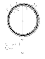
- FIG. 1 shows an exemplary cage 20, which may be used for a roller bearing, for instance, a self-aligning spherical roller bearing.
- the cage 20 may be formed by press-molding or stamping a metal plate or by injection-molding a synthetic resin.
- the cage has a main portion 22, an outward flange portion 24 extending outwardly in the radial direction from a side of the main portion, and an inward flange portion 26 extending outwardly in the radial direction from the opposite side of the main portion.
- a plurality of pockets 28 is formed in the main portion 22. Each pocket retains 28 a single generally cylindrically shaped roller 30 that is rollable therein.
- the main portion 22 disposed between the pockets 28 defines the inner diameter surface of the cage D3 and the inward flange 26 extends outward therefrom.
- Figure 4 shows additional detail with the inner most inner diameter of the cage indicated by D3.
- the main portion 22 disposed between the pockets 28 defines bridges and the inward flange 26 extends radially outward therefrom.
- the inward flange 26 may be turned radially outward from the main portion 22 so that the main portion 22, for instance, the bridges defined by the pockets, may define the innermost surface of the cage.
- the main portion 22 may be conically shaped so the outward flange portion extends radially outward from a larger diameter side of the main portion and the inward flange portion extends radially outward from a small diameter side of the main portion, the smaller diameter portion being indicated by D3.
- the main portion may also be cylindrical rather than conical.
- the inward flange is turned at an angle 90° relative to the bridges.
- roller retainers may be provided adjacent the pockets.
- Figures 5-7A , 7B show an embodiment of the cage with the roller retainer 32' formed on the outward flange 24.
- Figures 8-11 show an embodiment of the cage with the roller retainer 32 formed on the inward flange 26.
- the roller retainers 32,32' are preferably arranged in the center of each of the pockets 28 and engage recessed portions 34 in axial faces of the rollers 30.
- the roller recess portions 34 may be circular in shape and located at the center of ends of the barrel-shaped rollers 30.
- the recesses formed on the ends of the barrel-shaped rollers may also have an annular shape that is concentric with the barrel-shaped rollers.
- the roller retention feature or retainer 32,32' formed on the inward flange may be machined, stamped, or coined.
- FIG. 4 shows an exemplary extended inner ring bearing that may be used in connection with the above described bearing cage.
- the extended inner ring bearing 50 has an inner ring 51 with an extension portion 52 and an outer ring 54 supercircumjacent to the inner ring with the rollers 30 disposed therebetween. Because the inward flange 26 extends radially outward, the bearing cage 30 has radial clearance to allow its use in connection with the bearing 50 having with the inner ring extended portion 51.
- the extended inner ring bearing inner ring extension portion 52 has an outer diameter surface with a diameter D1 that is greater in dimension than a diameter D2 of the outer diameter surface of the inner ring race.
- the inner most inner diameter D3 of the bearing cage 20 may be sized to allow it to be directed over the outer diameter surface D1 of the inner ring extension portion 52.
- sufficiently material may be added to the inward flange (i.e., a relatively large outer diameter) to provide the bearing cage with overall rigidity and strength.
- the bridges of the main portion 22 may be formed in the cage at a diameter, for instance, diameter D3, that is less than the roller pitch D4. This eliminates the need to use other components such as guide rings and other bridges that separate the rollers at a diameter greater than the roller pitch.
- the outwardly turned inner flange provides a location on the inner flange for the roller retainer 32.
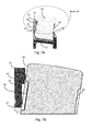
- the bearing cage may be provided with guide surfaces 60 formed on outward flange 24 for guiding the rollers 30.
- the guide surface may have cylindrically shaped contact surfaces that contact the axial ends of the rollers 30, so the rollers can be guided with a full line of contact 62 ( Fig. 8 ) across the roller face whether the outer flange portion is in its designed position or skewed from loading or manufacturing inaccuracies.
- the cylindrical shaped guide surfaces 60 may be formed on the outward flange portion 24 adjacent the pockets 28 on the inner side surfaces of the outward flange portion.
- the guide surfaces may be coined into a cylindrical shape ( Fig. 5,6 ) or otherwise formed as a protrusion ( Figs. 7A,7B ).
- the guide surfaces 60 may be continuous along the pocket 28 ( Fig. 8 ) or may be intermittent ( Figs. 5,6 ).
- the guide surfaces 60 may be arranged in a straight line 62 across the pocket, thus defining a polygonal orientation of the guide surfaces on the outward flange.
- the number of sides to the polygon may correspond to the number of pockets and rollers of the bearing.
- the guide surfaces are arranged to correspond to each side 70 of the polygon.
- the guide surfaces 60 may be cylindrically shaped and abut against the axial end faces of the rollers substantially uniformly with line contact 62 across the axial end surface of the roller.
- the line contact improves the lubrication film that should exist between the roller face and guide surfaces. Additionally, providing full line contact across the roller face allows the generally cylindrically shaped rollers to be guided by the guide surfaces with minimal skew no matter if the flanged portion of the cage is stamped in position as designed or is leaning inward or outward. Further, the line of contact enables guiding of the rollers within greater manufacturing tolerances. For instance, a greater variation may be allowed in the stamping and the roller will contact the cylindrical guide surface at a different height on the roller but with full line contact.
- the cylindrical shape design enhances lubrication in between the roller and the cage guide surface regardless of the direction of rotation or manufacturing variance associated with the stamping.
- the inward flange may be formed with the roller retainer, and the outward flange may be provided with a more robust guide surface feature.
- Figure 11 show an alternate embodiment of the bearing cage with the inward flange 26' comprising a two-piece assembly.
- the inward flange 26' comprises a ring-like, radially extending member 80 which is fitted onto a locater 82 at the inward most portion of the bridges 22.
- a locater 82 at the inward most portion of the bridges 22.
- an inward flange comprising a two-piece assembly enables the roller retainer 32 to be formed on the separate ring-like radially extending member 80 which may then be affixed to the locator 82 at the inward-most portion of the bridges.
- FIG 12 shows an alternate embodiment of a cage 120, which may also be used for a roller bearing, for instance, a self-aligning spherical roller bearing.
- the cage 120 may also be formed by press-molding or stamping a metal plate or by injection-molding a synthetic resin.
- the cage has a main portion 122, an outward flange portion 124 extending outwardly in the radial direction from a side of the main portion, and an inward flange portion 126 extending inwardly in the radial direction from the opposite side of the main portion.
- the main portion may be conically shaped so the outward flange portion extends radially outward from the large diameter side of the main portion and the inward flange portion extends radially inward from the small diameter side of the main portion.
- the main portion may also be cylindrical rather than conical.
- a plurality of pockets 128 (not shown in Figure 2 for ease of illustration) is formed in the main portion 122.
- Each pocket retains 128 a single barrel-shaped roller 130 that is rollable therein.
- tongues or roller retainers 132 are formed on the inner circumferential edges of outward flange portion 124 to extend into the pockets.
- the roller retainers 132 are preferably arranged in the center of each of the pockets 128 and engage recessed portions 134 in axial faces of the rollers 130 ( Fig. 14 ).
- the roller recess portions 134 may be circular in shape and located at the center of ends of the barrel-shaped rollers.
- the recesses formed on the ends of the barrel-shaped rollers may also have an annular shape that is concentric with the barrel-shaped rollers.
- cylindrical shaped guide surfaces 140 may be formed on the outward flange portion 124 adjacent the pockets 128 on the inner side surfaces of the outward flange portion.
- the guide surfaces may be coined into a cylindrical shape or otherwise formed as a protrusion.
- the guide surfaces 140 may be continuous along the pocket 128 or may be intermittent ( Fig. 20 ).
- the guide surfaces 140 may be arranged in a straight line 150 across the pocket, thus defining a polygonal orientation of the guide surfaces on the outward flange.
- the number of sides to the polygon may correspond to the number of pockets and rollers of the bearing.
- the guide surfaces are arranged to correspond to each side 150 of the polygon.
- the guide surfaces may be cylindrically shaped and abut against the axial end faces of the rollers substantially uniformly with line contact 142 ( Fig. 17 ) across the axial end surface of the roller.
- the line contact improves the lubrication film that should exist between the roller face and guide surfaces, and providing full line contact across the roller face allows the barrel-shaped rollers to be guided by the guide surfaces with minimal skew no matter if the flanged portion of the cage is stamped in position as designed or is leaning inward or outward.
- the line of contact enables guiding of the rollers within greater manufacturing tolerances, and the cylindrical shape design enhances lubrication in between the roller and the cage guide surface regardless of the direction of rotation or manufacturing variance associated with the stamping.
Landscapes
- Engineering & Computer Science (AREA)
- General Engineering & Computer Science (AREA)
- Mechanical Engineering (AREA)
- Rolling Contact Bearings (AREA)
- Support Of The Bearing (AREA)
Applications Claiming Priority (4)
| Application Number | Priority Date | Filing Date | Title |
|---|---|---|---|
| US201361820239P | 2013-05-07 | 2013-05-07 | |
| US14/036,350 US9033585B2 (en) | 2013-05-07 | 2013-09-25 | Spherical roller bearing cage with inward flange turned radially outward |
| US14/262,100 US9062715B2 (en) | 2013-05-07 | 2014-04-25 | Spherical roller bearing cage with cylindrical guidance contact surfaces |
| EP14795144.6A EP2994656B1 (fr) | 2013-05-07 | 2014-05-02 | Cage de roulement à rouleaux à surfaces de contact de guidage cylindriques et bride interne retournée vers l'extérieur dans un sens radial |
Related Parent Applications (2)
| Application Number | Title | Priority Date | Filing Date |
|---|---|---|---|
| EP14795144.6A Division EP2994656B1 (fr) | 2013-05-07 | 2014-05-02 | Cage de roulement à rouleaux à surfaces de contact de guidage cylindriques et bride interne retournée vers l'extérieur dans un sens radial |
| EP14795144.6A Division-Into EP2994656B1 (fr) | 2013-05-07 | 2014-05-02 | Cage de roulement à rouleaux à surfaces de contact de guidage cylindriques et bride interne retournée vers l'extérieur dans un sens radial |
Publications (1)
| Publication Number | Publication Date |
|---|---|
| EP2998598A1 true EP2998598A1 (fr) | 2016-03-23 |
Family
ID=51864844
Family Applications (2)
| Application Number | Title | Priority Date | Filing Date |
|---|---|---|---|
| EP15188655.3A Withdrawn EP2998598A1 (fr) | 2013-05-07 | 2014-05-02 | Cage de roulement à rouleaux sphériques avec bride intérieure tournée radialement vers l'extérieur |
| EP14795144.6A Not-in-force EP2994656B1 (fr) | 2013-05-07 | 2014-05-02 | Cage de roulement à rouleaux à surfaces de contact de guidage cylindriques et bride interne retournée vers l'extérieur dans un sens radial |
Family Applications After (1)
| Application Number | Title | Priority Date | Filing Date |
|---|---|---|---|
| EP14795144.6A Not-in-force EP2994656B1 (fr) | 2013-05-07 | 2014-05-02 | Cage de roulement à rouleaux à surfaces de contact de guidage cylindriques et bride interne retournée vers l'extérieur dans un sens radial |
Country Status (5)
| Country | Link |
|---|---|
| US (2) | US9033585B2 (fr) |
| EP (2) | EP2998598A1 (fr) |
| JP (2) | JP6261719B2 (fr) |
| CN (2) | CN105190065B (fr) |
| WO (1) | WO2014182569A2 (fr) |
Families Citing this family (9)
| Publication number | Priority date | Publication date | Assignee | Title |
|---|---|---|---|---|
| US10012265B2 (en) | 2007-12-06 | 2018-07-03 | Roller Bearing Company Of America, Inc. | Corrosion resistant bearing material |
| US9561845B2 (en) | 2007-12-06 | 2017-02-07 | Roller Bearing Company Of America, Inc. | Bearing installed on an aircraft structure |
| US10077808B2 (en) | 2013-12-18 | 2018-09-18 | Roller Bearing Company Of America, Inc. | Roller profile for hourglass roller bearings in aircraft |
| USD772964S1 (en) | 2014-01-17 | 2016-11-29 | Thk Co., Ltd. | Roller bearing |
| US9890814B2 (en) | 2014-06-03 | 2018-02-13 | Roller Bearing Company Of America, Inc. | Cage for hourglass roller bearings |
| USD771166S1 (en) * | 2014-06-19 | 2016-11-08 | Nsk Ltd. | Tapered roller bearing cage |
| JP1645893S (fr) * | 2019-01-10 | 2019-11-18 | ||
| JP7452196B2 (ja) * | 2020-03-31 | 2024-03-19 | 株式会社ジェイテクト | 円すいころ軸受 |
| DE102024207172B3 (de) * | 2024-07-30 | 2025-10-23 | Aktiebolaget Skf | Pendelrollenlager mit radial versetzten Käfigstegen |
Citations (5)
| Publication number | Priority date | Publication date | Assignee | Title |
|---|---|---|---|---|
| US1668112A (en) * | 1927-06-04 | 1928-05-01 | Gen Motors Corp | Cage for antifriction bearings |
| JP2004076928A (ja) * | 2002-06-19 | 2004-03-11 | Nsk Ltd | 転がり軸受用合成樹脂製保持器及び転がり軸受 |
| EP1961981A1 (fr) * | 2005-12-16 | 2008-08-27 | Ntn Corporation | Dispositif de palier pour roue |
| FR2925943A1 (fr) * | 2007-12-28 | 2009-07-03 | Snr Roulements Sa | Assemblage pour roulement a rouleaux coniques et son procede de fabrication |
| EP2309144A1 (fr) * | 2008-07-18 | 2011-04-13 | NTN Corporation | Cage estampée, palier à rouleaux à auto-alignement, et procédé de fabrication de cage estampée |
Family Cites Families (23)
| Publication number | Priority date | Publication date | Assignee | Title |
|---|---|---|---|---|
| JPS6077816U (ja) * | 1983-11-04 | 1985-05-30 | 日本精工株式会社 | ころ軸受 |
| SE447011B (sv) * | 1985-12-10 | 1986-10-20 | Skf Ab | Rullhallare for ett rullager |
| DE3723168C2 (de) * | 1987-07-14 | 1995-11-02 | Kugelfischer G Schaefer & Co | Kegelrollenlager |
| SE462443B (sv) | 1988-11-14 | 1990-06-25 | Skf Ab | Rullhaallare foer rullar i ett rullager |
| JP3039087B2 (ja) | 1991-12-05 | 2000-05-08 | 日本精工株式会社 | 保持器付自動調心ころ軸受 |
| JP3477835B2 (ja) | 1993-10-12 | 2003-12-10 | 日本精工株式会社 | 保持器付自動調心ころ軸受 |
| SE500988C2 (sv) | 1993-10-28 | 1994-10-17 | Skf Ab | Flerradigt sfäriskt rullager |
| US5586826A (en) | 1994-12-19 | 1996-12-24 | Skf Sverige Ab | Roller bearing provided with roller skew control and long life characteristics |
| JP3529191B2 (ja) | 1995-04-26 | 2004-05-24 | 日本精工株式会社 | 保持器付自動調心ころ軸受と保持器付自動調心ころ軸受用保持器の製造方法 |
| US6186669B1 (en) * | 1998-06-04 | 2001-02-13 | Nsk Ltd. | Roller cage for roller bearing |
| WO2005093273A1 (fr) * | 2004-03-26 | 2005-10-06 | Nsk Ltd. | Roulement à rouleaux auto-alignants |
| JP2005344742A (ja) * | 2004-05-31 | 2005-12-15 | Nsk Ltd | 自動調心ころ軸受 |
| CN101379312A (zh) * | 2005-12-16 | 2009-03-04 | Ntn株式会社 | 车轮用轴承装置 |
| WO2008056562A1 (fr) | 2006-11-09 | 2008-05-15 | Ntn Corporation | Roulement à rouleaux coniques |
| FR2925944B1 (fr) * | 2007-12-28 | 2010-05-14 | Roulements Soc Nouvelle | Assemblage pour roulement a rouleaux coniques et son procede de montage |
| US20110255820A1 (en) | 2008-04-23 | 2011-10-20 | Cooper Roller Bearings Company Limited | Roller bearing |
| JP2010025230A (ja) * | 2008-07-18 | 2010-02-04 | Ntn Corp | 打抜き保持器、自動調心ころ軸受、及び打抜き保持器の製造方法 |
| JP2010112473A (ja) * | 2008-11-06 | 2010-05-20 | Ntn Corp | ころ軸受用保持器とこの保持器を備えたころ軸受、およびころ軸受の製造方法 |
| JP2010249226A (ja) * | 2009-04-15 | 2010-11-04 | Ntn Corp | 円筒ころ軸受用保持器およびこれを備えた円筒ころ軸受 |
| DE102009055753A1 (de) | 2009-11-25 | 2011-05-26 | Schaeffler Technologies Gmbh & Co. Kg | Kegelrollenlager |
| DE102010019069A1 (de) * | 2010-05-03 | 2011-11-03 | Schaeffler Technologies Gmbh & Co. Kg | Axialkäfig für zylindrische Wälzkörper |
| DE102011084750A1 (de) * | 2011-10-19 | 2013-04-25 | Schaeffler Technologies AG & Co. KG | Zylinderrollenlager |
| CN202326741U (zh) * | 2011-11-23 | 2012-07-11 | 宁波中和汽配有限公司 | 滚柱轴承用保持架 |
-
2013
- 2013-09-25 US US14/036,350 patent/US9033585B2/en active Active
-
2014
- 2014-04-25 US US14/262,100 patent/US9062715B2/en active Active
- 2014-05-02 EP EP15188655.3A patent/EP2998598A1/fr not_active Withdrawn
- 2014-05-02 JP JP2016512972A patent/JP6261719B2/ja not_active Expired - Fee Related
- 2014-05-02 CN CN201480026030.8A patent/CN105190065B/zh not_active Expired - Fee Related
- 2014-05-02 WO PCT/US2014/036611 patent/WO2014182569A2/fr not_active Ceased
- 2014-05-02 CN CN201710281694.4A patent/CN107269709A/zh active Pending
- 2014-05-02 EP EP14795144.6A patent/EP2994656B1/fr not_active Not-in-force
-
2017
- 2017-02-03 JP JP2017018428A patent/JP2017101832A/ja active Pending
Patent Citations (5)
| Publication number | Priority date | Publication date | Assignee | Title |
|---|---|---|---|---|
| US1668112A (en) * | 1927-06-04 | 1928-05-01 | Gen Motors Corp | Cage for antifriction bearings |
| JP2004076928A (ja) * | 2002-06-19 | 2004-03-11 | Nsk Ltd | 転がり軸受用合成樹脂製保持器及び転がり軸受 |
| EP1961981A1 (fr) * | 2005-12-16 | 2008-08-27 | Ntn Corporation | Dispositif de palier pour roue |
| FR2925943A1 (fr) * | 2007-12-28 | 2009-07-03 | Snr Roulements Sa | Assemblage pour roulement a rouleaux coniques et son procede de fabrication |
| EP2309144A1 (fr) * | 2008-07-18 | 2011-04-13 | NTN Corporation | Cage estampée, palier à rouleaux à auto-alignement, et procédé de fabrication de cage estampée |
Also Published As
| Publication number | Publication date |
|---|---|
| US9033585B2 (en) | 2015-05-19 |
| US9062715B2 (en) | 2015-06-23 |
| US20140334761A1 (en) | 2014-11-13 |
| CN107269709A (zh) | 2017-10-20 |
| WO2014182569A2 (fr) | 2014-11-13 |
| US20140334762A1 (en) | 2014-11-13 |
| EP2994656A2 (fr) | 2016-03-16 |
| JP2016521339A (ja) | 2016-07-21 |
| JP6261719B2 (ja) | 2018-01-17 |
| EP2994656A4 (fr) | 2016-12-14 |
| JP2017101832A (ja) | 2017-06-08 |
| EP2994656B1 (fr) | 2019-03-06 |
| CN105190065A (zh) | 2015-12-23 |
| CN105190065B (zh) | 2020-07-31 |
| WO2014182569A3 (fr) | 2015-10-29 |
Similar Documents
| Publication | Publication Date | Title |
|---|---|---|
| EP2994656B1 (fr) | Cage de roulement à rouleaux à surfaces de contact de guidage cylindriques et bride interne retournée vers l'extérieur dans un sens radial | |
| US5039231A (en) | Bearing cage | |
| JP5597410B2 (ja) | 分割型保持器のセグメント及び転がり軸受 | |
| KR101757095B1 (ko) | 조향 칼럼 지지 베어링 | |
| US20110299805A1 (en) | Prong Cage for an Angular Contact Ball Bearing and Method for Assembling an Angular Contact Ball Bearing | |
| US20160281774A1 (en) | Tapered roller bearing | |
| US20140301683A1 (en) | Split cage for a bearing | |
| US9316255B2 (en) | Split cage and roller bearing | |
| JP2008175257A (ja) | 深溝玉軸受 | |
| US10465745B2 (en) | Thrust roller bearing cage and thrust roller bearing | |
| JP7485948B2 (ja) | 自動調心ころ軸受用保持器 | |
| CN111164318B (zh) | 带有缩短的凸缘的推力轴承保持架 | |
| US10527096B2 (en) | Rolling bearing | |
| US9033586B2 (en) | Two piece cage for a needle bearing | |
| KR20190115374A (ko) | 테이퍼 롤러 베어링 | |
| US9541132B2 (en) | Snap-fit box cage assembly | |
| CN106931038B (zh) | 包括设置有线材的保持架和密封件的轴承 | |
| US9909620B2 (en) | Radial roller cage with centerline guidance | |
| US8529137B2 (en) | Radial bearing cage with contact feature | |
| JP2012219822A (ja) | 円すいころ軸受 | |
| KR20190024277A (ko) | 앵귤러 컨택트 볼 베어링 | |
| US20150285305A1 (en) | Method of forming sheet metal bearing cage with inner and outer retention and roller-cage assembly for a bearing | |
| JP2017125616A5 (fr) | ||
| WO2021235022A1 (fr) | Dispositif de retenue de palier à rouleau à alignement automatique | |
| KR20160082776A (ko) | 이물환경 개선용 볼 베어링용 리테이너 |
Legal Events
| Date | Code | Title | Description |
|---|---|---|---|
| PUAI | Public reference made under article 153(3) epc to a published international application that has entered the european phase |
Free format text: ORIGINAL CODE: 0009012 |
|
| AC | Divisional application: reference to earlier application |
Ref document number: 2994656 Country of ref document: EP Kind code of ref document: P |
|
| AK | Designated contracting states |
Kind code of ref document: A1 Designated state(s): AL AT BE BG CH CY CZ DE DK EE ES FI FR GB GR HR HU IE IS IT LI LT LU LV MC MK MT NL NO PL PT RO RS SE SI SK SM TR |
|
| AX | Request for extension of the european patent |
Extension state: BA ME |
|
| 17P | Request for examination filed |
Effective date: 20160809 |
|
| RBV | Designated contracting states (corrected) |
Designated state(s): AL AT BE BG CH CY CZ DE DK EE ES FI FR GB GR HR HU IE IS IT LI LT LU LV MC MK MT NL NO PL PT RO RS SE SI SK SM TR |
|
| 17Q | First examination report despatched |
Effective date: 20170928 |
|
| STAA | Information on the status of an ep patent application or granted ep patent |
Free format text: STATUS: THE APPLICATION IS DEEMED TO BE WITHDRAWN |
|
| 18D | Application deemed to be withdrawn |
Effective date: 20190430 |