EP2998656A1 - Climatiseur - Google Patents
Climatiseur Download PDFInfo
- Publication number
- EP2998656A1 EP2998656A1 EP15150084.0A EP15150084A EP2998656A1 EP 2998656 A1 EP2998656 A1 EP 2998656A1 EP 15150084 A EP15150084 A EP 15150084A EP 2998656 A1 EP2998656 A1 EP 2998656A1
- Authority
- EP
- European Patent Office
- Prior art keywords
- refrigerant
- tube
- air conditioner
- heat exchanger
- header
- Prior art date
- Legal status (The legal status is an assumption and is not a legal conclusion. Google has not performed a legal analysis and makes no representation as to the accuracy of the status listed.)
- Granted
Links
Images
Classifications
-
- F—MECHANICAL ENGINEERING; LIGHTING; HEATING; WEAPONS; BLASTING
- F24—HEATING; RANGES; VENTILATING
- F24F—AIR-CONDITIONING; AIR-HUMIDIFICATION; VENTILATION; USE OF AIR CURRENTS FOR SCREENING
- F24F1/00—Room units for air-conditioning, e.g. separate or self-contained units or units receiving primary air from a central station
- F24F1/06—Separate outdoor units, e.g. outdoor unit to be linked to a separate room comprising a compressor and a heat exchanger
- F24F1/14—Heat exchangers specially adapted for separate outdoor units
-
- F—MECHANICAL ENGINEERING; LIGHTING; HEATING; WEAPONS; BLASTING
- F24—HEATING; RANGES; VENTILATING
- F24F—AIR-CONDITIONING; AIR-HUMIDIFICATION; VENTILATION; USE OF AIR CURRENTS FOR SCREENING
- F24F1/00—Room units for air-conditioning, e.g. separate or self-contained units or units receiving primary air from a central station
- F24F1/06—Separate outdoor units, e.g. outdoor unit to be linked to a separate room comprising a compressor and a heat exchanger
- F24F1/26—Refrigerant piping
- F24F1/30—Refrigerant piping for use inside the separate outdoor units
-
- F—MECHANICAL ENGINEERING; LIGHTING; HEATING; WEAPONS; BLASTING
- F25—REFRIGERATION OR COOLING; COMBINED HEATING AND REFRIGERATION SYSTEMS; HEAT PUMP SYSTEMS; MANUFACTURE OR STORAGE OF ICE; LIQUEFACTION SOLIDIFICATION OF GASES
- F25B—REFRIGERATION MACHINES, PLANTS OR SYSTEMS; COMBINED HEATING AND REFRIGERATION SYSTEMS; HEAT PUMP SYSTEMS
- F25B13/00—Compression machines, plants or systems, with reversible cycle
-
- F—MECHANICAL ENGINEERING; LIGHTING; HEATING; WEAPONS; BLASTING
- F25—REFRIGERATION OR COOLING; COMBINED HEATING AND REFRIGERATION SYSTEMS; HEAT PUMP SYSTEMS; MANUFACTURE OR STORAGE OF ICE; LIQUEFACTION SOLIDIFICATION OF GASES
- F25B—REFRIGERATION MACHINES, PLANTS OR SYSTEMS; COMBINED HEATING AND REFRIGERATION SYSTEMS; HEAT PUMP SYSTEMS
- F25B30/00—Heat pumps
- F25B30/02—Heat pumps of the compression type
-
- F—MECHANICAL ENGINEERING; LIGHTING; HEATING; WEAPONS; BLASTING
- F25—REFRIGERATION OR COOLING; COMBINED HEATING AND REFRIGERATION SYSTEMS; HEAT PUMP SYSTEMS; MANUFACTURE OR STORAGE OF ICE; LIQUEFACTION SOLIDIFICATION OF GASES
- F25B—REFRIGERATION MACHINES, PLANTS OR SYSTEMS; COMBINED HEATING AND REFRIGERATION SYSTEMS; HEAT PUMP SYSTEMS
- F25B39/00—Evaporators; Condensers
-
- F—MECHANICAL ENGINEERING; LIGHTING; HEATING; WEAPONS; BLASTING
- F28—HEAT EXCHANGE IN GENERAL
- F28D—HEAT-EXCHANGE APPARATUS, NOT PROVIDED FOR IN ANOTHER SUBCLASS, IN WHICH THE HEAT-EXCHANGE MEDIA DO NOT COME INTO DIRECT CONTACT
- F28D1/00—Heat-exchange apparatus having stationary conduit assemblies for one heat-exchange medium only, the media being in contact with different sides of the conduit wall, in which the other heat-exchange medium is a large body of fluid, e.g. domestic or motor car radiators
- F28D1/02—Heat-exchange apparatus having stationary conduit assemblies for one heat-exchange medium only, the media being in contact with different sides of the conduit wall, in which the other heat-exchange medium is a large body of fluid, e.g. domestic or motor car radiators with heat-exchange conduits immersed in the body of fluid
- F28D1/0233—Heat-exchange apparatus having stationary conduit assemblies for one heat-exchange medium only, the media being in contact with different sides of the conduit wall, in which the other heat-exchange medium is a large body of fluid, e.g. domestic or motor car radiators with heat-exchange conduits immersed in the body of fluid with air flow channels
-
- F—MECHANICAL ENGINEERING; LIGHTING; HEATING; WEAPONS; BLASTING
- F28—HEAT EXCHANGE IN GENERAL
- F28D—HEAT-EXCHANGE APPARATUS, NOT PROVIDED FOR IN ANOTHER SUBCLASS, IN WHICH THE HEAT-EXCHANGE MEDIA DO NOT COME INTO DIRECT CONTACT
- F28D1/00—Heat-exchange apparatus having stationary conduit assemblies for one heat-exchange medium only, the media being in contact with different sides of the conduit wall, in which the other heat-exchange medium is a large body of fluid, e.g. domestic or motor car radiators
- F28D1/02—Heat-exchange apparatus having stationary conduit assemblies for one heat-exchange medium only, the media being in contact with different sides of the conduit wall, in which the other heat-exchange medium is a large body of fluid, e.g. domestic or motor car radiators with heat-exchange conduits immersed in the body of fluid
- F28D1/04—Heat-exchange apparatus having stationary conduit assemblies for one heat-exchange medium only, the media being in contact with different sides of the conduit wall, in which the other heat-exchange medium is a large body of fluid, e.g. domestic or motor car radiators with heat-exchange conduits immersed in the body of fluid with tubular conduits
- F28D1/047—Heat-exchange apparatus having stationary conduit assemblies for one heat-exchange medium only, the media being in contact with different sides of the conduit wall, in which the other heat-exchange medium is a large body of fluid, e.g. domestic or motor car radiators with heat-exchange conduits immersed in the body of fluid with tubular conduits the conduits being bent, e.g. in a serpentine or zig-zag
- F28D1/0477—Heat-exchange apparatus having stationary conduit assemblies for one heat-exchange medium only, the media being in contact with different sides of the conduit wall, in which the other heat-exchange medium is a large body of fluid, e.g. domestic or motor car radiators with heat-exchange conduits immersed in the body of fluid with tubular conduits the conduits being bent, e.g. in a serpentine or zig-zag the conduits being bent in a serpentine or zig-zag
-
- F—MECHANICAL ENGINEERING; LIGHTING; HEATING; WEAPONS; BLASTING
- F28—HEAT EXCHANGE IN GENERAL
- F28F—DETAILS OF HEAT-EXCHANGE AND HEAT-TRANSFER APPARATUS, OF GENERAL APPLICATION
- F28F17/00—Removing ice or water from heat-exchange apparatus
- F28F17/005—Means for draining condensates from heat exchangers, e.g. from evaporators
-
- F—MECHANICAL ENGINEERING; LIGHTING; HEATING; WEAPONS; BLASTING
- F25—REFRIGERATION OR COOLING; COMBINED HEATING AND REFRIGERATION SYSTEMS; HEAT PUMP SYSTEMS; MANUFACTURE OR STORAGE OF ICE; LIQUEFACTION SOLIDIFICATION OF GASES
- F25B—REFRIGERATION MACHINES, PLANTS OR SYSTEMS; COMBINED HEATING AND REFRIGERATION SYSTEMS; HEAT PUMP SYSTEMS
- F25B2313/00—Compression machines, plants or systems with reversible cycle not otherwise provided for
- F25B2313/025—Compression machines, plants or systems with reversible cycle not otherwise provided for using multiple outdoor units
-
- F—MECHANICAL ENGINEERING; LIGHTING; HEATING; WEAPONS; BLASTING
- F25—REFRIGERATION OR COOLING; COMBINED HEATING AND REFRIGERATION SYSTEMS; HEAT PUMP SYSTEMS; MANUFACTURE OR STORAGE OF ICE; LIQUEFACTION SOLIDIFICATION OF GASES
- F25B—REFRIGERATION MACHINES, PLANTS OR SYSTEMS; COMBINED HEATING AND REFRIGERATION SYSTEMS; HEAT PUMP SYSTEMS
- F25B2313/00—Compression machines, plants or systems with reversible cycle not otherwise provided for
- F25B2313/025—Compression machines, plants or systems with reversible cycle not otherwise provided for using multiple outdoor units
- F25B2313/0253—Compression machines, plants or systems with reversible cycle not otherwise provided for using multiple outdoor units in parallel arrangements
- F25B2313/02533—Compression machines, plants or systems with reversible cycle not otherwise provided for using multiple outdoor units in parallel arrangements during heating
-
- F—MECHANICAL ENGINEERING; LIGHTING; HEATING; WEAPONS; BLASTING
- F25—REFRIGERATION OR COOLING; COMBINED HEATING AND REFRIGERATION SYSTEMS; HEAT PUMP SYSTEMS; MANUFACTURE OR STORAGE OF ICE; LIQUEFACTION SOLIDIFICATION OF GASES
- F25B—REFRIGERATION MACHINES, PLANTS OR SYSTEMS; COMBINED HEATING AND REFRIGERATION SYSTEMS; HEAT PUMP SYSTEMS
- F25B2313/00—Compression machines, plants or systems with reversible cycle not otherwise provided for
- F25B2313/025—Compression machines, plants or systems with reversible cycle not otherwise provided for using multiple outdoor units
- F25B2313/0254—Compression machines, plants or systems with reversible cycle not otherwise provided for using multiple outdoor units in series arrangements
- F25B2313/02541—Compression machines, plants or systems with reversible cycle not otherwise provided for using multiple outdoor units in series arrangements during cooling
-
- F—MECHANICAL ENGINEERING; LIGHTING; HEATING; WEAPONS; BLASTING
- F25—REFRIGERATION OR COOLING; COMBINED HEATING AND REFRIGERATION SYSTEMS; HEAT PUMP SYSTEMS; MANUFACTURE OR STORAGE OF ICE; LIQUEFACTION SOLIDIFICATION OF GASES
- F25B—REFRIGERATION MACHINES, PLANTS OR SYSTEMS; COMBINED HEATING AND REFRIGERATION SYSTEMS; HEAT PUMP SYSTEMS
- F25B2400/00—Component parts or details not otherwise provided for in this subclass
- F25B2400/07—Details of compressors or related parts
- F25B2400/075—Details of compressors or related parts with parallel compressors
-
- F—MECHANICAL ENGINEERING; LIGHTING; HEATING; WEAPONS; BLASTING
- F25—REFRIGERATION OR COOLING; COMBINED HEATING AND REFRIGERATION SYSTEMS; HEAT PUMP SYSTEMS; MANUFACTURE OR STORAGE OF ICE; LIQUEFACTION SOLIDIFICATION OF GASES
- F25B—REFRIGERATION MACHINES, PLANTS OR SYSTEMS; COMBINED HEATING AND REFRIGERATION SYSTEMS; HEAT PUMP SYSTEMS
- F25B2400/00—Component parts or details not otherwise provided for in this subclass
- F25B2400/13—Economisers
-
- F—MECHANICAL ENGINEERING; LIGHTING; HEATING; WEAPONS; BLASTING
- F25—REFRIGERATION OR COOLING; COMBINED HEATING AND REFRIGERATION SYSTEMS; HEAT PUMP SYSTEMS; MANUFACTURE OR STORAGE OF ICE; LIQUEFACTION SOLIDIFICATION OF GASES
- F25B—REFRIGERATION MACHINES, PLANTS OR SYSTEMS; COMBINED HEATING AND REFRIGERATION SYSTEMS; HEAT PUMP SYSTEMS
- F25B39/00—Evaporators; Condensers
- F25B39/02—Evaporators
- F25B39/028—Evaporators having distributing means
-
- F—MECHANICAL ENGINEERING; LIGHTING; HEATING; WEAPONS; BLASTING
- F25—REFRIGERATION OR COOLING; COMBINED HEATING AND REFRIGERATION SYSTEMS; HEAT PUMP SYSTEMS; MANUFACTURE OR STORAGE OF ICE; LIQUEFACTION SOLIDIFICATION OF GASES
- F25B—REFRIGERATION MACHINES, PLANTS OR SYSTEMS; COMBINED HEATING AND REFRIGERATION SYSTEMS; HEAT PUMP SYSTEMS
- F25B41/00—Fluid-circulation arrangements
- F25B41/40—Fluid line arrangements
- F25B41/42—Arrangements for diverging or converging flows, e.g. branch lines or junctions
-
- F—MECHANICAL ENGINEERING; LIGHTING; HEATING; WEAPONS; BLASTING
- F28—HEAT EXCHANGE IN GENERAL
- F28F—DETAILS OF HEAT-EXCHANGE AND HEAT-TRANSFER APPARATUS, OF GENERAL APPLICATION
- F28F9/00—Casings; Header boxes; Auxiliary supports for elements; Auxiliary members within casings
- F28F9/02—Header boxes; End plates
- F28F9/026—Header boxes; End plates with static flow control means, e.g. with means for uniformly distributing heat exchange media into conduits
- F28F9/027—Header boxes; End plates with static flow control means, e.g. with means for uniformly distributing heat exchange media into conduits in the form of distribution pipes
- F28F9/0275—Header boxes; End plates with static flow control means, e.g. with means for uniformly distributing heat exchange media into conduits in the form of distribution pipes with multiple branch pipes
Definitions
- the present disclosure relates to an air conditioner.
- Air conditioners are appliances that maintain indoor air at the most proper state according to use and purpose thereof.
- such an air conditioner includes a compressor, a condenser, an expansion device, and an evaporator.
- the air conditioner has a refrigerant cycle in which compression, condensation, expansion, and evaporation processes of refrigerant are performed to cool or heat a predetermined space.
- an outdoor heat exchanger provided in an outdoor unit may serve as a condenser, and an indoor heat exchanger provided in an indoor unit may serve as an evaporator.
- the indoor heat exchanger may serve as a condenser, and the outdoor heat exchanger may serve as an evaporator.
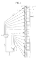
- Fig. 1 is a view of an outdoor heat exchanger according to a related art.
- the refrigerant flows in directions opposite to each other when cooling and heating operations are performed.
- the heat-exchanged refrigerant is mixed in the first and second distributors 5 and 6 to flow toward an indoor heat exchanger.
- the outdoor heat exchanger 1 functions as an evaporator (see a dotted arrow).
- the refrigerant may be heat-exchanged with the outdoor air while flowing in the refrigerant tubes 2.
- the heat-exchanged refrigerant may be mixed in the header 4 to flow to a compressor-side.
- the refrigerant passing through the outdoor heat exchanger 1 is in a high-temperature high-pressure gaseous state.
- the number of branch paths branched into the outdoor heat exchanger 1 may be reduced, and the branch paths may increase in length.
- the refrigerant when a flow path of the refrigerant increases in length, the refrigerant increases in flow rate to reduce a condensation pressure, thereby improving condensation efficiency, i.e., a ratio in which the refrigerant changes into gaseous phase.
- a gaseous refrigerant of the refrigerant in two-phase has a relatively large pressure loss while flowing
- the pressure loss i.e., reduction of an evaporation pressure may be prevented to improve evaporation efficiency.
- the condensation pressure in the outdoor heat exchanger increases to deteriorate condensation efficiency.
- the evaporation pressure in the outdoor heat exchanger decreases to deteriorate evaporation efficiency.
- Embodiments provide an air conditioner including an outdoor heat exchanger having improved heat-exchange efficiency.
- the invention is defined by the claims.
- the air conditioner may further include a third valve disposed in the connection tube.
- an air conditioner in another embodiment, includes: a compressor; a flow switching part disposed at an outlet-side of the compressor to switch a flow direction of refrigerant according to a cooling or heating operation; an outdoor heat exchanger connected to the flow switching part, the outdoor heat exchanger including a plurality of refrigerant tubes for guiding the refrigerant heat exchanged with outdoor air; a main expansion valve disposed at one side of the outdoor heat exchanger; a first inlet/outlet tube extending from the flow switching part to the outdoor heat exchanger; and a second inlet/outlet tube extending from the outdoor heat exchanger to the main expansion valve, wherein the outdoor heat exchanger includes: a header defining a flow space for the refrigerant, the header including an upper header and a lower header; a plurality of refrigerant inflow tubes extending from the header to the plurality of refrigerant tubes; and a bypass tube extending from the lower header to an outlet-side of the outdoor heat exchanger and having a bent part.
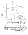
- the air conditioner 10 includes a plurality of compressors 110 and 112 and oil separators 120 and 122 disposed at an outlet-side of each of the plurality of compressors 110 and 112 to separate the oil from the refrigerant discharged from each of the plurality of compressors 110 and 112.
- the plurality of compressors 110 and 112 include a first compressor 110 and a second compressor 112, which are connected in parallel to each other.
- a discharge temperature sensor 114 for detecting a temperature of the compressed refrigerant may be disposed at an outlet-side of each of the first and second compressors 110 and 112.
- the air conditioner 10 includes a supercooling passage 273 disposed at an outlet-side of the supercooling heat exchanger 270 to divide the second refrigerant from the first refrigerant.
- the second refrigerant of the supercooling passage 273 may be introduced into the supercooling heat exchanger 270 and then be heat-exchanged with the first refrigerant to flow to an inlet-side of a gas/liquid separator 280.
- the air conditioner 10 may further include a supercooling discharge temperature sensor 276 for detecting a temperature of the second refrigerant passing through the supercooling heat exchanger 270.
- the gas/liquid separator 280 may be configured to separate a gaseous refrigerant from the refrigerant before the refrigerant is introduced into the compressors 110 and 112.
- the separated gaseous refrigerant may be introduced into the compressors 110 and 112.
- the air conditioner 10 includes a first inlet/outlet tube 201a connected from the flow switching part 130 to one side of the outdoor heat exchanger 200 and a second inlet/outlet tube 201b extending from the other side of the outdoor heat exchanger 200 to the main expansion device 260.
- the plurality of refrigerant tubes 202 may be bent to lengthily extend.
- the plurality of refrigerant tubes 202 may extend to a rear side of the ground and then extend forward.
- each of the plurality of refrigerant tubes 202 may have a U-shape.
- the outdoor heat exchanger 200 may include a coupling plate 203 for supporting the refrigerant tubes 202.
- the coupling plate 203 includes a first plate 203a having a bent shape to support one side of the refrigerant tubes 202 and a second plate 203b supporting the other side of the refrigerant tubes 202.
- Each of the first and second plates 203a and 203b lengthily extends in a vertical direction.
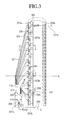
- the outdoor heat exchanger 200 may further include the header 205 defining a flow space of the refrigerant.
- the header 205 Through the header 205, the refrigerant is divided and introduced into the plurality of refrigerant tubes 202, or the refrigerant heat-exchanged in the plurality of refrigerant tubes 202 is mixed with each other.
- the header 205 lengthily extends in a vertical direction to correspond to a direction in which the first plate 203a extends.
- the refrigerant in the header 205 may be introduced into the refrigerant tubes 202 through the plurality of refrigerant inflow tubes 232.
- the refrigerant in the refrigerant tubes 202 may be introduced into the header 205 through the refrigerant inflow tube 232.
- the air conditioner 10 may further include a plurality of distributors 210 and 220 for dividing and introducing the refrigerant into the outdoor heat exchanger 200 when the heating operation is performed.
- the plurality of distributors 210 and 220 include the first distributor 210 and the second distributor 220.
- the air conditioner 10 may further include a first distribution tube 211 and a second distribution tube 221 branched from the second inlet/outlet tube 201b to the first distributor 210 and the second distributor 220.
- the first and second distribution tubes 211 and 221 may extend from a branch portion 201c to the first and second distributors 210 and 220.
- the air conditioner 10 may further include a first valve 215 disposed in the first distribution tube 211 to adjust a refrigerant flow rate flowing in the first distribution tube 211 and a second valve 225 disposed in the second distribution tube 221 to adjust a refrigerant flow rate flowing in the second distribution tube 221.
- Each of the first and second valves 215 and 225 may include an electric expansion valve (EEV) of which an opened degree is adjustable.
- EEV electric expansion valve
- the air conditioner 10 may further include a plurality of capillary tubes 207 extending from the first and second distributors 210 and 220 to the plurality of refrigerant tubes 202.
- the air conditioner 10 performs a heating operation, the refrigerant is divided to flow into the first and second distributors 210 and 220, and the divided refrigerant moves into the refrigerant tubes 202 through the plurality of capillary tubes 207.
- the air conditioner 10 may further include a branch tube 209 connecting each of the plurality of capillary tubes 207 to the refrigerant tube 202.
- the branch tube 209 may divide the refrigerant flowing in the capillary tube 207 in two directions, into one refrigerant tube 202 and the other refrigerant tube 202.
- the branch tube 209 may include a branch tube having a Y shape.
- the branch tube 209 may be provided in plurality to correspond to the number of the plurality of capillary tubes 207.
- the refrigerant introduced into the refrigerant tubes 202 through the plurality of capillary tubes 207 connected to the first distributor 210 is heat-exchanged and introduced into the upper header 205a of the header 205.
- the refrigerant introduced into the refrigerant tubes 202 through the plurality of capillary tubes 207 connected to the second distributor 220 is heat-exchanged and introduced into the lower header 205b of the header 205.
- the air conditioner 10 may further include a check valve 240 disposed between the upper header 205a and the lower header 205b.
- the check valve 240 may allow the refrigerant to flow from the lower header 205b to the upper header 205a and may restrict the flow of the refrigerant from the upper header 205a to the lower header 205b.
- the refrigerant introduced into the refrigerant tube 202 through the second distributor 220 may be heat-exchanged and then be introduced into the lower header 205b.
- the refrigerant introduced into the lower header 205b may be guided by the check valve 240 to flow to the upper header 205a.
- the refrigerant introduced into the refrigerant tube 202 through the first distributor 210 may be heat-exchanged and introduced into the upper header 205a and then be mixed with the refrigerant introduced from the lower header 205b to move to the first inlet/outlet tube 201a.
- the air conditioner 10 may further include a connection tube 230 extending from one spot of the first distribution tube 211 to the lower header 205b.
- a third valve 235 for adjusting a refrigerant flow rate within the connection tube 230 may be disposed.
- the third valve 235 may include an on/off controllable solenoid valve and an EEV of which an opened degree is adjustable.
- the refrigerant flowing from the first distributor 210 to the first distribution tube 211 may be introduced into the lower header 205b through the connection tube 230.
- the supercooling refrigerant passing through the supercooling heat exchanger 270 may cool the heat generating component of the electronic unit while passing through the heat dissipation plate 265 and then be decompressed in the main expansion valve 260.
- the refrigerant discharged from the outdoor heat exchanger 200 may flow toward the indoor unit via the heat dissipation plate 265 and the supercooling heat exchanger 270.
- the refrigerant may be expanded and evaporated in the indoor unit and then be absorbed into the first and the second compressors 110 and 120 via the flow switching part 130 and the gas/liquid separator 280. This refrigeration cycle may be repeatedly performed.
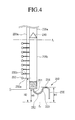
- Fig. 4 is a schematic view illustrating a bypass tube of the outdoor heat exchanger according to an embodiment.
- the bypass tube 250 extends from the lower portion of the lower header 205b of the header 205 toward the second inlet/outlet tube 201b.
- the bypass tube 250 may be curved or bent at least two times.
- the bypass tube 250 may further include a second extension part 253 extending upward from the first extension part 251 and a first bent part 252 disposed at one spot between the first extension part 251 and the second extension part 253 to switch an extension direction of the bypass tube 250.
- the bypass tube 250 may further include a third extension part 255 extending downward from the second extension part 253 and a second bent part 254 disposed at one spot between the second extension part 253 and the third extension part 255 to switch the extension direction of the bypass tube 250.
- the bypass tube 250 may have a structure in which a pressure of the refrigerant flowing in the bypass tube 250 is less than that of the refrigerant in the lowermost inflow tube 232a.
- the height H1 of the uppermost portion of the bypass tube 250 may correspond to a height of the second bent part 254 of the bypass tube 250.
- a pressure of the refrigerant in the lowermost inflow tube 232a may be greater than that in the bypass tube 250.
- introduction of the liquid refrigerant existing in the lower header 205b into the lowermost tube 232a may be prevented.
Landscapes
- Engineering & Computer Science (AREA)
- Mechanical Engineering (AREA)
- General Engineering & Computer Science (AREA)
- Physics & Mathematics (AREA)
- Thermal Sciences (AREA)
- Chemical & Material Sciences (AREA)
- Combustion & Propulsion (AREA)
- Other Air-Conditioning Systems (AREA)
Applications Claiming Priority (1)
| Application Number | Priority Date | Filing Date | Title |
|---|---|---|---|
| KR1020140099194A KR101550549B1 (ko) | 2014-08-01 | 2014-08-01 | 공기 조화기 |
Publications (2)
| Publication Number | Publication Date |
|---|---|
| EP2998656A1 true EP2998656A1 (fr) | 2016-03-23 |
| EP2998656B1 EP2998656B1 (fr) | 2020-08-05 |
Family
ID=52292754
Family Applications (1)
| Application Number | Title | Priority Date | Filing Date |
|---|---|---|---|
| EP15150084.0A Not-in-force EP2998656B1 (fr) | 2014-08-01 | 2015-01-05 | Climatiseur |
Country Status (3)
| Country | Link |
|---|---|
| US (1) | US9897351B2 (fr) |
| EP (1) | EP2998656B1 (fr) |
| KR (1) | KR101550549B1 (fr) |
Cited By (2)
| Publication number | Priority date | Publication date | Assignee | Title |
|---|---|---|---|---|
| EP3306234A1 (fr) * | 2016-10-05 | 2018-04-11 | Mitsubishi Heavy Industries Thermal Systems, Ltd. | Évaporateur et circuit réfrigérant |
| CN110657550A (zh) * | 2019-10-21 | 2020-01-07 | 宁波奥克斯电气股份有限公司 | 一种压缩机回油控制方法、装置和空调器 |
Families Citing this family (21)
| Publication number | Priority date | Publication date | Assignee | Title |
|---|---|---|---|---|
| EP3147591B1 (fr) * | 2014-05-19 | 2022-04-13 | Mitsubishi Electric Corporation | Dispositif de climatisation |
| JP5949831B2 (ja) * | 2014-05-28 | 2016-07-13 | ダイキン工業株式会社 | 冷凍装置 |
| WO2016031186A1 (fr) * | 2014-08-27 | 2016-03-03 | 日本電気株式会社 | Dispositif de refroidissement à changement de phase, et procédé de refroidissement à changement de phase |
| US10156387B2 (en) * | 2014-12-18 | 2018-12-18 | Lg Electronics Inc. | Outdoor device for an air conditioner |
| JP6573484B2 (ja) * | 2015-05-29 | 2019-09-11 | 日立ジョンソンコントロールズ空調株式会社 | 熱交換器 |
| JP6678332B2 (ja) * | 2016-03-07 | 2020-04-08 | パナソニックIpマネジメント株式会社 | 空気調和機の室外ユニットおよび制御方法 |
| US10578377B2 (en) * | 2016-03-31 | 2020-03-03 | Mitsubishi Electric Corporation | Heat exchanger and refrigeration cycle apparatus |
| WO2018029817A1 (fr) * | 2016-08-10 | 2018-02-15 | 三菱電機株式会社 | Dispositif à cycle de réfrigération |
| EP3614075B1 (fr) * | 2017-08-08 | 2022-07-20 | Mitsubishi Electric Corporation | Unité d'échange de chaleur et appareil à cycle de réfrigération |
| WO2019106755A1 (fr) * | 2017-11-29 | 2019-06-06 | 三菱電機株式会社 | Climatiseur |
| KR102447943B1 (ko) * | 2018-02-05 | 2022-09-28 | 엘지전자 주식회사 | 공기조화기 |
| CN110470074A (zh) | 2018-05-11 | 2019-11-19 | 开利公司 | 换热器、热泵系统和换热方法 |
| JP6466047B1 (ja) * | 2018-08-22 | 2019-02-06 | 三菱電機株式会社 | 熱交換器及び空気調和装置 |
| US11221151B2 (en) * | 2019-01-15 | 2022-01-11 | Johnson Controls Technology Company | Hot gas reheat systems and methods |
| CN112240608B (zh) * | 2019-07-18 | 2023-06-27 | 木村工机株式会社 | 热交换器及空调机 |
| CN214039044U (zh) * | 2020-10-27 | 2021-08-24 | 青岛海尔空调器有限总公司 | 换热装置和空调器 |
| CN113719901B (zh) * | 2021-08-26 | 2023-09-19 | Tcl空调器(中山)有限公司 | 空调换热组件以及空调器 |
| CN216694078U (zh) * | 2021-09-19 | 2022-06-07 | 青岛海尔空调器有限总公司 | 换热器及空调器 |
| JP7239857B1 (ja) * | 2021-09-30 | 2023-03-15 | ダイキン工業株式会社 | 空気調和機 |
| CN116951562A (zh) * | 2022-04-14 | 2023-10-27 | 东芝开利空调(中国)有限公司 | 空调装置 |
| CN116147233B (zh) * | 2023-04-21 | 2023-06-30 | 广东美博智能环境设备有限公司 | 一种高效率的制冷设备换热管 |
Citations (6)
| Publication number | Priority date | Publication date | Assignee | Title |
|---|---|---|---|---|
| EP2204625A1 (fr) * | 2009-01-06 | 2010-07-07 | Lg Electronics Inc. | Climatiseur et procédé de fonctionnement du dégivrage correspondant |
| EP2455689A2 (fr) * | 2010-11-18 | 2012-05-23 | LG Electronics Inc. | Climatiseur |
| EP2618077A2 (fr) * | 2012-01-20 | 2013-07-24 | LG Electronics, Inc. | Échangeur de chaleur et climatiseur comprenant celui-ci |
| EP2618076A2 (fr) * | 2012-01-20 | 2013-07-24 | LG Electronics, Inc. | Échangeur de chaleur extérieur et climatiseur comprenant celui-ci |
| EP2623873A2 (fr) * | 2012-02-03 | 2013-08-07 | LG Electronics, Inc. | Échangeur de chaleur extérieur et climatiseur comprenant celui-ci |
| KR20140022319A (ko) * | 2012-08-14 | 2014-02-24 | 엘지전자 주식회사 | 실외 열교환기 |
Family Cites Families (17)
| Publication number | Priority date | Publication date | Assignee | Title |
|---|---|---|---|---|
| US3078689A (en) * | 1963-02-26 | japhet | ||
| US2148415A (en) * | 1933-07-13 | 1939-02-21 | Westinghouse Electric & Mfg Co | Reversible refrigerating apparatus for heating and cooling |
| US2785540A (en) * | 1953-09-30 | 1957-03-19 | Westinghouse Electric Corp | Heat pumps |
| US3132490A (en) * | 1961-08-28 | 1964-05-12 | Carrier Corp | Reverse cycle heat pump |
| US3580005A (en) * | 1969-04-01 | 1971-05-25 | Carrier Corp | Refrigeration system |
| ES461192A1 (es) * | 1976-07-29 | 1978-12-01 | Matsushita Electric Industrial Co Ltd | Una bomba de calor. |
| US4240269A (en) * | 1979-05-29 | 1980-12-23 | Carrier Corporation | Heat pump system |
| US4407137A (en) * | 1981-03-16 | 1983-10-04 | Carrier Corporation | Fast defrost heat exchanger |
| JPS58141808A (ja) * | 1982-02-19 | 1983-08-23 | Hitachi Ltd | 圧延機の板厚制御方法及び装置 |
| US4483156A (en) * | 1984-04-27 | 1984-11-20 | The Trane Company | Bi-directional variable subcooler for heat pumps |
| JP2902853B2 (ja) * | 1992-04-27 | 1999-06-07 | 三洋電機株式会社 | 空気調和機 |
| JP3352469B2 (ja) * | 1992-07-14 | 2002-12-03 | 東芝キヤリア株式会社 | 空気調和装置 |
| JP2000146258A (ja) | 1998-11-16 | 2000-05-26 | Mitsubishi Heavy Ind Ltd | 空気調和機およびその制御方法 |
| JP2008256304A (ja) | 2007-04-06 | 2008-10-23 | Daikin Ind Ltd | 冷凍装置 |
| EP2617077A4 (fr) | 2010-09-16 | 2013-07-24 | Hewlett Packard Development Co | Dispositif de commutation à l'échelle nanométrique |
| KR101288745B1 (ko) * | 2011-10-27 | 2013-07-23 | 엘지전자 주식회사 | 공기조화기 |
| KR101872783B1 (ko) | 2012-02-03 | 2018-06-29 | 엘지전자 주식회사 | 실외 열교환기 |
-
2014
- 2014-08-01 KR KR1020140099194A patent/KR101550549B1/ko active Active
-
2015
- 2015-01-05 EP EP15150084.0A patent/EP2998656B1/fr not_active Not-in-force
- 2015-05-14 US US14/712,600 patent/US9897351B2/en active Active
Patent Citations (6)
| Publication number | Priority date | Publication date | Assignee | Title |
|---|---|---|---|---|
| EP2204625A1 (fr) * | 2009-01-06 | 2010-07-07 | Lg Electronics Inc. | Climatiseur et procédé de fonctionnement du dégivrage correspondant |
| EP2455689A2 (fr) * | 2010-11-18 | 2012-05-23 | LG Electronics Inc. | Climatiseur |
| EP2618077A2 (fr) * | 2012-01-20 | 2013-07-24 | LG Electronics, Inc. | Échangeur de chaleur et climatiseur comprenant celui-ci |
| EP2618076A2 (fr) * | 2012-01-20 | 2013-07-24 | LG Electronics, Inc. | Échangeur de chaleur extérieur et climatiseur comprenant celui-ci |
| EP2623873A2 (fr) * | 2012-02-03 | 2013-08-07 | LG Electronics, Inc. | Échangeur de chaleur extérieur et climatiseur comprenant celui-ci |
| KR20140022319A (ko) * | 2012-08-14 | 2014-02-24 | 엘지전자 주식회사 | 실외 열교환기 |
Cited By (2)
| Publication number | Priority date | Publication date | Assignee | Title |
|---|---|---|---|---|
| EP3306234A1 (fr) * | 2016-10-05 | 2018-04-11 | Mitsubishi Heavy Industries Thermal Systems, Ltd. | Évaporateur et circuit réfrigérant |
| CN110657550A (zh) * | 2019-10-21 | 2020-01-07 | 宁波奥克斯电气股份有限公司 | 一种压缩机回油控制方法、装置和空调器 |
Also Published As
| Publication number | Publication date |
|---|---|
| US9897351B2 (en) | 2018-02-20 |
| KR101550549B1 (ko) | 2015-09-04 |
| EP2998656B1 (fr) | 2020-08-05 |
| US20160033179A1 (en) | 2016-02-04 |
Similar Documents
| Publication | Publication Date | Title |
|---|---|---|
| EP2998656B1 (fr) | Climatiseur | |
| EP3015793B1 (fr) | Climatisation et procédé de commande correspondant | |
| US10156387B2 (en) | Outdoor device for an air conditioner | |
| US10161656B2 (en) | Air conditioner having a bending tube which alters the flow of the refrigerant prior to entering the distributor | |
| US10655917B2 (en) | Heat exchanger and air conditioning device | |
| US20160252282A1 (en) | Air conditioner and evaporator inlet header distributor therefor | |
| US20160327317A1 (en) | Heat exchanger and air conditioning apparatus | |
| US10041705B2 (en) | Outdoor device for an air conditioner | |
| KR101647908B1 (ko) | 공기 조화 장치 | |
| US9239179B2 (en) | Air conditioner | |
| KR101694614B1 (ko) | 공기 조화기 | |
| EP2985549B1 (fr) | Climatiseur | |
| JP2014122770A (ja) | 熱交換器 | |
| KR101644703B1 (ko) | 공기 조화기 및 그 제어방법 | |
| KR101626215B1 (ko) | 공기 조화기 | |
| KR101626216B1 (ko) | 공기 조화기 | |
| KR101630955B1 (ko) | 공기 조화기 및 그 제어방법 | |
| KR20190055972A (ko) | 공기조화기 | |
| KR102100662B1 (ko) | 공기 조화기 | |
| KR20250072788A (ko) | 공기 조화기 | |
| JP7146077B2 (ja) | 熱交換器及び空気調和装置 | |
| KR20180096403A (ko) | 공기 조화기 | |
| KR20180098763A (ko) | 공기 조화기 | |
| KR20090069918A (ko) | 공기조화 시스템 |
Legal Events
| Date | Code | Title | Description |
|---|---|---|---|
| PUAI | Public reference made under article 153(3) epc to a published international application that has entered the european phase |
Free format text: ORIGINAL CODE: 0009012 |
|
| 17P | Request for examination filed |
Effective date: 20150205 |
|
| AK | Designated contracting states |
Kind code of ref document: A1 Designated state(s): AL AT BE BG CH CY CZ DE DK EE ES FI FR GB GR HR HU IE IS IT LI LT LU LV MC MK MT NL NO PL PT RO RS SE SI SK SM TR |
|
| AX | Request for extension of the european patent |
Extension state: BA ME |
|
| RBV | Designated contracting states (corrected) |
Designated state(s): AL AT BE BG CH CY CZ DE DK EE ES FI FR GB GR HR HU IE IS IT LI LT LU LV MC MK MT NL NO PL PT RO RS SE SI SK SM TR |
|
| GRAP | Despatch of communication of intention to grant a patent |
Free format text: ORIGINAL CODE: EPIDOSNIGR1 |
|
| STAA | Information on the status of an ep patent application or granted ep patent |
Free format text: STATUS: GRANT OF PATENT IS INTENDED |
|
| RIC1 | Information provided on ipc code assigned before grant |
Ipc: F28F 9/02 20060101ALI20200218BHEP Ipc: F24F 1/14 20110101AFI20200218BHEP Ipc: F25B 13/00 20060101ALI20200218BHEP Ipc: F28D 1/047 20060101ALI20200218BHEP Ipc: F24F 1/30 20110101ALI20200218BHEP Ipc: F28D 1/02 20060101ALI20200218BHEP Ipc: F25B 41/00 20060101ALI20200218BHEP Ipc: F25B 39/00 20060101ALI20200218BHEP Ipc: F25B 39/02 20060101ALI20200218BHEP Ipc: F28F 17/00 20060101ALI20200218BHEP Ipc: F25B 30/02 20060101ALI20200218BHEP |
|
| INTG | Intention to grant announced |
Effective date: 20200311 |
|
| GRAS | Grant fee paid |
Free format text: ORIGINAL CODE: EPIDOSNIGR3 |
|
| GRAA | (expected) grant |
Free format text: ORIGINAL CODE: 0009210 |
|
| STAA | Information on the status of an ep patent application or granted ep patent |
Free format text: STATUS: THE PATENT HAS BEEN GRANTED |
|
| AK | Designated contracting states |
Kind code of ref document: B1 Designated state(s): AL AT BE BG CH CY CZ DE DK EE ES FI FR GB GR HR HU IE IS IT LI LT LU LV MC MK MT NL NO PL PT RO RS SE SI SK SM TR |
|
| REG | Reference to a national code |
Ref country code: GB Ref legal event code: FG4D |
|
| REG | Reference to a national code |
Ref country code: CH Ref legal event code: EP |
|
| REG | Reference to a national code |
Ref country code: AT Ref legal event code: REF Ref document number: 1299251 Country of ref document: AT Kind code of ref document: T Effective date: 20200815 |
|
| REG | Reference to a national code |
Ref country code: DE Ref legal event code: R096 Ref document number: 602015056771 Country of ref document: DE |
|
| REG | Reference to a national code |
Ref country code: IE Ref legal event code: FG4D |
|
| REG | Reference to a national code |
Ref country code: LT Ref legal event code: MG4D |
|
| REG | Reference to a national code |
Ref country code: NL Ref legal event code: MP Effective date: 20200805 |
|
| REG | Reference to a national code |
Ref country code: AT Ref legal event code: MK05 Ref document number: 1299251 Country of ref document: AT Kind code of ref document: T Effective date: 20200805 |
|
| PG25 | Lapsed in a contracting state [announced via postgrant information from national office to epo] |
Ref country code: FI Free format text: LAPSE BECAUSE OF FAILURE TO SUBMIT A TRANSLATION OF THE DESCRIPTION OR TO PAY THE FEE WITHIN THE PRESCRIBED TIME-LIMIT Effective date: 20200805 Ref country code: GR Free format text: LAPSE BECAUSE OF FAILURE TO SUBMIT A TRANSLATION OF THE DESCRIPTION OR TO PAY THE FEE WITHIN THE PRESCRIBED TIME-LIMIT Effective date: 20201106 Ref country code: PT Free format text: LAPSE BECAUSE OF FAILURE TO SUBMIT A TRANSLATION OF THE DESCRIPTION OR TO PAY THE FEE WITHIN THE PRESCRIBED TIME-LIMIT Effective date: 20201207 Ref country code: BG Free format text: LAPSE BECAUSE OF FAILURE TO SUBMIT A TRANSLATION OF THE DESCRIPTION OR TO PAY THE FEE WITHIN THE PRESCRIBED TIME-LIMIT Effective date: 20201105 Ref country code: LT Free format text: LAPSE BECAUSE OF FAILURE TO SUBMIT A TRANSLATION OF THE DESCRIPTION OR TO PAY THE FEE WITHIN THE PRESCRIBED TIME-LIMIT Effective date: 20200805 Ref country code: ES Free format text: LAPSE BECAUSE OF FAILURE TO SUBMIT A TRANSLATION OF THE DESCRIPTION OR TO PAY THE FEE WITHIN THE PRESCRIBED TIME-LIMIT Effective date: 20200805 Ref country code: HR Free format text: LAPSE BECAUSE OF FAILURE TO SUBMIT A TRANSLATION OF THE DESCRIPTION OR TO PAY THE FEE WITHIN THE PRESCRIBED TIME-LIMIT Effective date: 20200805 Ref country code: AT Free format text: LAPSE BECAUSE OF FAILURE TO SUBMIT A TRANSLATION OF THE DESCRIPTION OR TO PAY THE FEE WITHIN THE PRESCRIBED TIME-LIMIT Effective date: 20200805 Ref country code: NO Free format text: LAPSE BECAUSE OF FAILURE TO SUBMIT A TRANSLATION OF THE DESCRIPTION OR TO PAY THE FEE WITHIN THE PRESCRIBED TIME-LIMIT Effective date: 20201105 Ref country code: SE Free format text: LAPSE BECAUSE OF FAILURE TO SUBMIT A TRANSLATION OF THE DESCRIPTION OR TO PAY THE FEE WITHIN THE PRESCRIBED TIME-LIMIT Effective date: 20200805 |
|
| PG25 | Lapsed in a contracting state [announced via postgrant information from national office to epo] |
Ref country code: IS Free format text: LAPSE BECAUSE OF FAILURE TO SUBMIT A TRANSLATION OF THE DESCRIPTION OR TO PAY THE FEE WITHIN THE PRESCRIBED TIME-LIMIT Effective date: 20201205 Ref country code: PL Free format text: LAPSE BECAUSE OF FAILURE TO SUBMIT A TRANSLATION OF THE DESCRIPTION OR TO PAY THE FEE WITHIN THE PRESCRIBED TIME-LIMIT Effective date: 20200805 Ref country code: RS Free format text: LAPSE BECAUSE OF FAILURE TO SUBMIT A TRANSLATION OF THE DESCRIPTION OR TO PAY THE FEE WITHIN THE PRESCRIBED TIME-LIMIT Effective date: 20200805 Ref country code: NL Free format text: LAPSE BECAUSE OF FAILURE TO SUBMIT A TRANSLATION OF THE DESCRIPTION OR TO PAY THE FEE WITHIN THE PRESCRIBED TIME-LIMIT Effective date: 20200805 Ref country code: LV Free format text: LAPSE BECAUSE OF FAILURE TO SUBMIT A TRANSLATION OF THE DESCRIPTION OR TO PAY THE FEE WITHIN THE PRESCRIBED TIME-LIMIT Effective date: 20200805 |
|
| PG25 | Lapsed in a contracting state [announced via postgrant information from national office to epo] |
Ref country code: SM Free format text: LAPSE BECAUSE OF FAILURE TO SUBMIT A TRANSLATION OF THE DESCRIPTION OR TO PAY THE FEE WITHIN THE PRESCRIBED TIME-LIMIT Effective date: 20200805 Ref country code: RO Free format text: LAPSE BECAUSE OF FAILURE TO SUBMIT A TRANSLATION OF THE DESCRIPTION OR TO PAY THE FEE WITHIN THE PRESCRIBED TIME-LIMIT Effective date: 20200805 Ref country code: EE Free format text: LAPSE BECAUSE OF FAILURE TO SUBMIT A TRANSLATION OF THE DESCRIPTION OR TO PAY THE FEE WITHIN THE PRESCRIBED TIME-LIMIT Effective date: 20200805 Ref country code: DK Free format text: LAPSE BECAUSE OF FAILURE TO SUBMIT A TRANSLATION OF THE DESCRIPTION OR TO PAY THE FEE WITHIN THE PRESCRIBED TIME-LIMIT Effective date: 20200805 Ref country code: CZ Free format text: LAPSE BECAUSE OF FAILURE TO SUBMIT A TRANSLATION OF THE DESCRIPTION OR TO PAY THE FEE WITHIN THE PRESCRIBED TIME-LIMIT Effective date: 20200805 |
|
| REG | Reference to a national code |
Ref country code: DE Ref legal event code: R097 Ref document number: 602015056771 Country of ref document: DE |
|
| PG25 | Lapsed in a contracting state [announced via postgrant information from national office to epo] |
Ref country code: AL Free format text: LAPSE BECAUSE OF FAILURE TO SUBMIT A TRANSLATION OF THE DESCRIPTION OR TO PAY THE FEE WITHIN THE PRESCRIBED TIME-LIMIT Effective date: 20200805 |
|
| PLBE | No opposition filed within time limit |
Free format text: ORIGINAL CODE: 0009261 |
|
| STAA | Information on the status of an ep patent application or granted ep patent |
Free format text: STATUS: NO OPPOSITION FILED WITHIN TIME LIMIT |
|
| PG25 | Lapsed in a contracting state [announced via postgrant information from national office to epo] |
Ref country code: SK Free format text: LAPSE BECAUSE OF FAILURE TO SUBMIT A TRANSLATION OF THE DESCRIPTION OR TO PAY THE FEE WITHIN THE PRESCRIBED TIME-LIMIT Effective date: 20200805 |
|
| 26N | No opposition filed |
Effective date: 20210507 |
|
| PG25 | Lapsed in a contracting state [announced via postgrant information from national office to epo] |
Ref country code: IT Free format text: LAPSE BECAUSE OF FAILURE TO SUBMIT A TRANSLATION OF THE DESCRIPTION OR TO PAY THE FEE WITHIN THE PRESCRIBED TIME-LIMIT Effective date: 20200805 |
|
| PG25 | Lapsed in a contracting state [announced via postgrant information from national office to epo] |
Ref country code: MC Free format text: LAPSE BECAUSE OF FAILURE TO SUBMIT A TRANSLATION OF THE DESCRIPTION OR TO PAY THE FEE WITHIN THE PRESCRIBED TIME-LIMIT Effective date: 20200805 Ref country code: SI Free format text: LAPSE BECAUSE OF FAILURE TO SUBMIT A TRANSLATION OF THE DESCRIPTION OR TO PAY THE FEE WITHIN THE PRESCRIBED TIME-LIMIT Effective date: 20200805 |
|
| REG | Reference to a national code |
Ref country code: CH Ref legal event code: PL |
|
| GBPC | Gb: european patent ceased through non-payment of renewal fee |
Effective date: 20210105 |
|
| PG25 | Lapsed in a contracting state [announced via postgrant information from national office to epo] |
Ref country code: LU Free format text: LAPSE BECAUSE OF NON-PAYMENT OF DUE FEES Effective date: 20210105 |
|
| REG | Reference to a national code |
Ref country code: BE Ref legal event code: MM Effective date: 20210131 |
|
| PG25 | Lapsed in a contracting state [announced via postgrant information from national office to epo] |
Ref country code: FR Free format text: LAPSE BECAUSE OF NON-PAYMENT OF DUE FEES Effective date: 20210131 |
|
| PG25 | Lapsed in a contracting state [announced via postgrant information from national office to epo] |
Ref country code: CH Free format text: LAPSE BECAUSE OF NON-PAYMENT OF DUE FEES Effective date: 20210131 Ref country code: GB Free format text: LAPSE BECAUSE OF NON-PAYMENT OF DUE FEES Effective date: 20210105 Ref country code: LI Free format text: LAPSE BECAUSE OF NON-PAYMENT OF DUE FEES Effective date: 20210131 |
|
| PG25 | Lapsed in a contracting state [announced via postgrant information from national office to epo] |
Ref country code: IE Free format text: LAPSE BECAUSE OF NON-PAYMENT OF DUE FEES Effective date: 20210105 |
|
| PG25 | Lapsed in a contracting state [announced via postgrant information from national office to epo] |
Ref country code: IS Free format text: LAPSE BECAUSE OF FAILURE TO SUBMIT A TRANSLATION OF THE DESCRIPTION OR TO PAY THE FEE WITHIN THE PRESCRIBED TIME-LIMIT Effective date: 20201205 |
|
| PG25 | Lapsed in a contracting state [announced via postgrant information from national office to epo] |
Ref country code: BE Free format text: LAPSE BECAUSE OF NON-PAYMENT OF DUE FEES Effective date: 20210131 |
|
| PG25 | Lapsed in a contracting state [announced via postgrant information from national office to epo] |
Ref country code: HU Free format text: LAPSE BECAUSE OF FAILURE TO SUBMIT A TRANSLATION OF THE DESCRIPTION OR TO PAY THE FEE WITHIN THE PRESCRIBED TIME-LIMIT; INVALID AB INITIO Effective date: 20150105 |
|
| PGFP | Annual fee paid to national office [announced via postgrant information from national office to epo] |
Ref country code: DE Payment date: 20221205 Year of fee payment: 9 |
|
| PG25 | Lapsed in a contracting state [announced via postgrant information from national office to epo] |
Ref country code: CY Free format text: LAPSE BECAUSE OF FAILURE TO SUBMIT A TRANSLATION OF THE DESCRIPTION OR TO PAY THE FEE WITHIN THE PRESCRIBED TIME-LIMIT Effective date: 20200805 |
|
| PG25 | Lapsed in a contracting state [announced via postgrant information from national office to epo] |
Ref country code: MK Free format text: LAPSE BECAUSE OF FAILURE TO SUBMIT A TRANSLATION OF THE DESCRIPTION OR TO PAY THE FEE WITHIN THE PRESCRIBED TIME-LIMIT Effective date: 20200805 |
|
| REG | Reference to a national code |
Ref country code: DE Ref legal event code: R119 Ref document number: 602015056771 Country of ref document: DE |
|
| PG25 | Lapsed in a contracting state [announced via postgrant information from national office to epo] |
Ref country code: MT Free format text: LAPSE BECAUSE OF FAILURE TO SUBMIT A TRANSLATION OF THE DESCRIPTION OR TO PAY THE FEE WITHIN THE PRESCRIBED TIME-LIMIT Effective date: 20200805 |
|
| PG25 | Lapsed in a contracting state [announced via postgrant information from national office to epo] |
Ref country code: DE Free format text: LAPSE BECAUSE OF NON-PAYMENT OF DUE FEES Effective date: 20240801 |
|
| PG25 | Lapsed in a contracting state [announced via postgrant information from national office to epo] |
Ref country code: DE Free format text: LAPSE BECAUSE OF NON-PAYMENT OF DUE FEES Effective date: 20240801 |
|
| PG25 | Lapsed in a contracting state [announced via postgrant information from national office to epo] |
Ref country code: TR Free format text: LAPSE BECAUSE OF FAILURE TO SUBMIT A TRANSLATION OF THE DESCRIPTION OR TO PAY THE FEE WITHIN THE PRESCRIBED TIME-LIMIT Effective date: 20200805 |