EP2998663A2 - Closure assembly for an air canal and a corresponding assembly of a building - Google Patents
Closure assembly for an air canal and a corresponding assembly of a building Download PDFInfo
- Publication number
- EP2998663A2 EP2998663A2 EP15173281.5A EP15173281A EP2998663A2 EP 2998663 A2 EP2998663 A2 EP 2998663A2 EP 15173281 A EP15173281 A EP 15173281A EP 2998663 A2 EP2998663 A2 EP 2998663A2
- Authority
- EP
- European Patent Office
- Prior art keywords
- closure
- channel
- flaps
- closed position
- elements
- Prior art date
- Legal status (The legal status is an assumption and is not a legal conclusion. Google has not performed a legal analysis and makes no representation as to the accuracy of the status listed.)
- Granted
Links
Images




Classifications
-
- F—MECHANICAL ENGINEERING; LIGHTING; HEATING; WEAPONS; BLASTING
- F24—HEATING; RANGES; VENTILATING
- F24F—AIR-CONDITIONING; AIR-HUMIDIFICATION; VENTILATION; USE OF AIR CURRENTS FOR SCREENING
- F24F13/00—Details common to, or for air-conditioning, air-humidification, ventilation or use of air currents for screening
- F24F13/08—Air-flow control members, e.g. louvres, grilles, flaps or guide plates
- F24F13/10—Air-flow control members, e.g. louvres, grilles, flaps or guide plates movable, e.g. dampers
- F24F13/14—Air-flow control members, e.g. louvres, grilles, flaps or guide plates movable, e.g. dampers built up of tilting members, e.g. louvre
- F24F13/1413—Air-flow control members, e.g. louvres, grilles, flaps or guide plates movable, e.g. dampers built up of tilting members, e.g. louvre using more than one tilting member, e.g. with several pivoting blades
-
- F—MECHANICAL ENGINEERING; LIGHTING; HEATING; WEAPONS; BLASTING
- F24—HEATING; RANGES; VENTILATING
- F24F—AIR-CONDITIONING; AIR-HUMIDIFICATION; VENTILATION; USE OF AIR CURRENTS FOR SCREENING
- F24F11/00—Control or safety arrangements
- F24F11/70—Control systems characterised by their outputs; Constructional details thereof
- F24F11/72—Control systems characterised by their outputs; Constructional details thereof for controlling the supply of treated air, e.g. its pressure
- F24F11/74—Control systems characterised by their outputs; Constructional details thereof for controlling the supply of treated air, e.g. its pressure for controlling air flow rate or air velocity
-
- F—MECHANICAL ENGINEERING; LIGHTING; HEATING; WEAPONS; BLASTING
- F24—HEATING; RANGES; VENTILATING
- F24F—AIR-CONDITIONING; AIR-HUMIDIFICATION; VENTILATION; USE OF AIR CURRENTS FOR SCREENING
- F24F13/00—Details common to, or for air-conditioning, air-humidification, ventilation or use of air currents for screening
- F24F13/08—Air-flow control members, e.g. louvres, grilles, flaps or guide plates
- F24F13/10—Air-flow control members, e.g. louvres, grilles, flaps or guide plates movable, e.g. dampers
- F24F13/14—Air-flow control members, e.g. louvres, grilles, flaps or guide plates movable, e.g. dampers built up of tilting members, e.g. louvre
- F24F13/1486—Air-flow control members, e.g. louvres, grilles, flaps or guide plates movable, e.g. dampers built up of tilting members, e.g. louvre characterised by bearings, pivots or hinges
-
- F—MECHANICAL ENGINEERING; LIGHTING; HEATING; WEAPONS; BLASTING
- F24—HEATING; RANGES; VENTILATING
- F24F—AIR-CONDITIONING; AIR-HUMIDIFICATION; VENTILATION; USE OF AIR CURRENTS FOR SCREENING
- F24F7/00—Ventilation
- F24F2007/0025—Ventilation using vent ports in a wall
Definitions
- the invention relates to a closure arrangement for an air duct and a corresponding building arrangement.
- the ventilation of buildings is often realized with the help of wall openings, in which optionally closable and openable wall boxes are used.
- these wall boxes are closed by means of back pressure flaps, which automatically open during ventilation of the building due to the air flow occurring, or which can be moved by motor driven between a closed and an open position.
- a generic ventilation flap is from the DE 20 2010 003 340 U1 known.
- a wall box in which a closure lid between an open position and a closed position driven by a pressure difference between the air pressure inside and outside the building against a self-adjusting mechanism provided by a restoring force automatically opens and closes.
- the known wall boxes often have the disadvantage that they represent a thermal bridge between the building interior and the building environment.
- it is from the DE 20 2006 006 327 U1 known to use in a wall box a motor displaceable between a closed and open position shutter which has an insulating body which has an outer contour which substantially corresponds to the inner contour of a ventilation duct.
- the adjusting mechanism is designed to displace the insulating body in a linear movement between the open and the closed position.
- the closure system is thus formed comparatively complex and in particular does not allow the automatic opening of the closure due to an incipient air flow, as generated for example by hoods for the removal of fumes.
- the closure arrangement according to the invention has a channel and at least two closure elements arranged therein, wherein the closure elements are pivotable between an open position in which they release a cross-section of the channel and a closed position in which they sealingly abut an inner circumference of the channel.
- the closure elements are arranged spaced along the longitudinal axis of the channel and in an air flow direction through the channel by a distance, so that in the closed position between the closure elements, a fluid-sealed space is formed.
- the closure arrangement according to the invention thus makes use of the significantly lower thermal conductivity of air compared to most solids.
- the enclosed between each two adjacent closure elements air volume acts just like a thermal barrier.
- the closure arrangement according to the invention is not restricted to a specific number of the closure elements used. Already two closure elements are sufficient to form the thermal barrier according to the invention in the form of a closed volume of air. Investigations have shown, however, that closure arrangements can be realized on the basis of the teaching according to the invention, which already have a heat transfer value of only about 1 W / (m 2 K) using three closure elements.
- the closure elements each have two flaps which have along their circumference a hinge side whose length corresponds to an inner dimension of the channel, and otherwise have a sealing contour which is adapted to a contour of the inner circumference of the channel.
- the flaps can be designed, for example, as one-sided hinged plastic flaps. If the channel is a round channel, can the flaps have substantially the shape of half a circular disc, wherein the straight side of the flap forms the hinge side.
- the two flaps of each closure element are arranged adjacent to each other with their hinge sides. This allows the flaps in the open position to assume a position in which they are folded on one another and extend along the longitudinal axis of the channel or parallel to it. Alternatively, in the open position, the flaps may also extend at an angle to the longitudinal axis of the channel. Basically, the position of the flaps in the open position should be selected according to the fact that the flaps in the open position represent the lowest possible flow resistance. This in turn depends on the geometry of the flaps. In principle, the flaps in the open position are to be arranged in such a way that they have the smallest possible cross-section in relation to the air flow flowing in the direction of air flow.
- the flaps have a dimension perpendicular to their respective hinge side, which is greater than the distance of the closure elements to each other, so that in the closed position in each case one of the flaps of a first closure element of the closure elements with one of the flaps of at least one further closure element of Closing elements overlap. It has been found that the volume of air trapped between the closure elements in the closed position of the closure arrangement in the longitudinal direction of the channel can only have a comparatively small dimension, which may for example also be smaller than the radius of a used circular channel.
- the overlapping flap sections of the adjoining closure elements are to be arranged such that the closure arrangement forms as low a flow resistance as possible in the open position.
- the flaps each have a step which extends spaced from the hinge side and parallel to the hinge side by the distance between the closure elements, so that the flaps lie in an overlapping region of the flaps and thus due their compact arrangement only have a very small cross section for the air flowing through the channel.
- the flaps are arranged as close to each other as possible in the open position and to largely suppress rattling of the flaps due to turbulence in the open position, at least a first of the closure elements, for example their side facing the hinge side having a spoiler having a raised portion via a step, which is arranged in the open position flaps in the overlapping region at a distance from a flap of another of the closure elements, which is arranged downstream of the first closure element is, so that the overlapping flaps are pressed against each other via an output of the flap having the spoiler, when the closure elements are flowed in the open position of an air flow.
- a first of the closure elements for example their side facing the hinge side having a spoiler having a raised portion via a step, which is arranged in the open position flaps in the overlapping region at a distance from a flap of another of the closure elements, which is arranged downstream of the first closure element is, so that the overlapping flaps are pressed against each other via an output of the flap having the spoiler
- the flaps are designed as cavity profiles which have an enclosed gas volume.
- the flaps themselves can for example be made of a plastic material, in particular of a plastic material with a low coefficient of thermal conductivity, for example by injection molding.
- the adjoining hinge sides of the flaps of each closure element are interconnected via an airtight web, wherein the airtight web may comprise a spring-actuated return element which, in the open position of the flaps, provides a restoring moment in the closed position.
- the restoring element can be designed, for example, in the form of an elastic rubber spring element, in which the hinge sides of the flaps are inserted at opposite longitudinal grooves. If the flaps are flown by an air flow, the flaps move under bias of the return spring element in the open position. If the air flow stops, the flaps are moved back into the closed position due to the restoring moment of the preloaded spring element.
- the flaps have a curved contour with a convex outer side and a concave inner side. Especially if the flaps partially overlap adjacent closure elements in the open position, the above-described curved contour of the flaps has the advantage that the closure assembly forms only a low flow resistance.
- the sealing contour comprises a compression seal, such as a rubber lip or a foam element, or a brush element, so that in the closed position between the inner circumference of the channel and the sealing contour, an impact gap is formed instead of an impact gap.
- the channel has an inner contour with varying diameter in the channel longitudinal direction, wherein the inner contour has chamfers along which the flaps are guided during their movement from the open position to the closed position with compression of the compression seal.
- the run-up slopes thus also have the function of forming a stop for the flaps in their movement between the open position and the closed position.
- an adjusting drive on the movement of the closure elements between the open position and the closed position
- this can be realized according to an embodiment of the invention such that the adjustment acts on the flaps of the rearmost in the air flow direction closure element, wherein the overlapping flaps with each other via coupling elements coupled together.
- the adjusting drive can then be surrounded in the open position by the flaps of the rearmost element in the air flow direction, or be in the slipstream of the closure elements.
- the adjustment is not only aerodynamically arranged, but also effectively protected from contamination, such as those contained in the vapors of a cooker hood.
- the coupling elements as a coupling rod, a Coupling rod or a coupling thread are formed, or have such elements, which extends at an angle 0 ° ⁇ ⁇ ⁇ 90 ° to the longitudinal axis of the channel and is thus connected at a different distance to the hinge sides with the overlapping flaps.
- an embodiment in which the closure arrangement is of modular design, in order to enable, at the discretion of the user and depending on a specific application situation, an efficient adaptability of the closure arrangement to the conditions encountered. It is provided that the channel is divided longitudinally into a plurality of channel sections which are releasably connected to each other, wherein in each of the channel sections of the closure elements is received. This embodiment makes it possible for any number of the channel sections with closure elements accommodated therein to be combined to form a closure arrangement according to the invention.
- the closure arrangement according to the invention can in particular also be used for retrofitting in already existing exhaust air duct systems. It is often the case that an already found wall box in a wall breakthrough of a building wall has an air passage cross-section with a deviating from the standard geometry. For example, an inserted in the wall breakthrough channel due to its installation situation have rounding, which makes the installation of a closure assembly for standardized pipe cross-sectional geometries difficult.
- the closure elements via an adjustment between the open position and the closed position are movable back and forth, wherein the adjustment Has at least one spring element which exerts a closing moment in the closed position on the closure elements.
- the closing moment exerted by the spring element on the closure elements is degressive, increases in the direction of the closed position and is maximum in the closed position.
- the flaps of the closure element have a coating, foliation, or coating to reduce the transmission of heat radiation, for example an aluminum foil coating.
- the channel has on its inner circumference per closure element has a circumferential spoiler, the extends from a channel inside and forms a local channel cross-sectional constriction, wherein the closure elements in the closed position abut against a free end edge of the respective spoiler, which forms a stop.
- this relates to a building arrangement with a building wall having a wall opening into which a wall box having an air passage cross-sectional geometry is inserted, wherein a closure arrangement of the type described above is inserted into the wall box.
- the channel has an outer geometry, which differs from the Lucas miclassqueritessgeometrie.
- a diameter compensation element for example a circumferential, elastic sealing element is arranged, which is designed to compensate for the deviation between the channel outer geometry and the Lucas miclassgeometrie.
- the outer dimensions of the channel are slightly undersized, in which case the required, fluidly sealed closure between the channel and the wall box is ensured by means of the compensating element.
- FIG. 1 shows in longitudinal cross section a simplest embodiment of the invention in a schematic representation.
- the left-hand opening of the channel 1 in the illustration forms the air inflow side, and accordingly the right-hand opening in the illustration is the air outflow side of the channel 1.
- the direction of air flow is indicated by the arrows R.
- the in FIG. 1 shown channel 1 is a circular channel and thus the drawn longitudinal axis X and the axis of symmetry of the channel.
- each closure element 2 has two opposing flaps 3, which are articulated via a hinge side extending perpendicular to the plane of the drawing.
- the hinge sides are perpendicular to the longitudinal axis X, so that the hinge sides of the opposing flaps 3 of each closure element 2 coincide.
- the hinges are provided in the form of an airtight web 9. This can for example be formed as a rubber-elastic component, in which the ends of the opposing flaps of each closure element 2 embedded are.
- the elastic webs 9 are biased so that they act in the open position as a return spring element, which exerts a restoring moment in the direction of the closed position on the flaps 3.
- closure element 2 engages an adjustment 10, with which the flaps 3 can be transferred against the bias of the webs 9 from the closed position to the open position.
- Adjacent flaps of adjacent closure elements are operatively coupled to each other via coupling elements 11.
- the flaps 3 are formed as hollow profiles and thus have over solid material flaps improved thermal insulation properties.
- the flaps 3 are shaped so that they are in the in FIG. 2 illustrated open position of the closure assembly represent the lowest possible air resistance and shield the adjusting member 10 to avoid air vortices and its contamination. Due to the curved outer contour of the flaps 3, the closure assembly forms an outer geometry in the open position, which has a low air resistance.
- the flaps 3 of the closure elements 2 are optimized in such a way that the closure arrangement in the open position, on the one hand, forms the least possible air resistance and, on the other hand, rattling of the flaps 3 is effectively suppressed due to turbulence on the closure arrangement.
- the FIG. 3 it can be seen that the closure assembly 1 is divided into three similar segments, each comprising a channel portion in which one of the closure elements 2 is accommodated. The channel sections can be freely combined with each other in order to combine any number of closure elements 2 according to a specific application, if necessary.
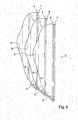
- FIG. 4 shows the closure elements 2 of the embodiment according to FIG. 3 in the open position.
- the channel 1 is not shown.
- the flaps 3 of the different closure arrangements overlap in the open position, wherein the flaps each have a step 6, which is formed at a distance from the hinge side 4 of the respective flap, which corresponds to the distance between the closure elements 2. This makes it possible for the flaps 3 to lie flat against one another in the overlapping region 7 of the flaps 3.
- the flaps 3 of the closure elements 2 have on their side opposite the hinge side 4 each have a spoiler 8, which has a raised paragraph over a step, which is located in the open position flaps 3 in the overlap region 7 at a distance to the flap 3 of each next, downstream arranged closure element 2 is arranged.
- the spoiler 8 produces an output, so that the flaps 3 are pressed against each other to avoid rattling and to bring the closure assembly 2 in a compact design as possible.
- the FIG. 5 clearly shows that due to the stage 6, the closure elements 2 in the open position can take a very compact design in which they represent a low air resistance.
- the channel 1 on its inner side an inner contour 12, with varying in the channel length X diameter.
- the inner contour 12 has chamfers, along which the flaps are guided in their movement between the open position and the closed position under compression of a compression seal on the outer periphery of the flaps.
- a spoiler 8 is formed on the inner circumference of the channel 1 per closure arrangement 2 and flap pair 3, extending from the inside of the channel 1 and extending circumferentially on the inside of the channel 1.
- Each spoiler 8 has a free end edge or spoiler edge, which forms a stop for the flaps 3.
- the flaps 3 are provided at their sealing edge, with which they rest in the closed position on the inside of the channel 1, with a fold to form a sealing ridge over which the flaps 3 sealingly abut against the inside of the channel 1.
- the sealing bar has the task of increasing the sealing area between the flap 3 and the channel 1.
Landscapes
- Engineering & Computer Science (AREA)
- Chemical & Material Sciences (AREA)
- Combustion & Propulsion (AREA)
- Mechanical Engineering (AREA)
- General Engineering & Computer Science (AREA)
- Physics & Mathematics (AREA)
- Fluid Mechanics (AREA)
- Air-Flow Control Members (AREA)
- Duct Arrangements (AREA)
Abstract
Die Erfindung betrifft eine Verschlussanordnung für einen Luftkanal, mit einem Kanal (1) sowie mindestens zwei in dem Kanal (1) angeordneten Verschlusselementen (2), wobei die Verschlusselemente (2) zwischen einer Offenstellung, in der die Verschlusselemente (2) einen Querschnitt des Kanals (1) freigeben, und einer Schließstellung, in der die Verschlusselemente (2) an einem Innenumfang des Kanals (1) dichtend anliegen, verschwenkbar sind, und wobei die Verschlusselemente (2) entlang der Längsachse (X) des Kanals (1) und in einer Luftströmungsrichtung (R) durch den Kanal (1) um einen Abstand voneinander beabstandet angeordnet sind, so dass in der Schließstellung zwischen den Verschlusselementen (2) ein fluidisch abgeschlossener Raum gebildet ist. Es wird weiterhin eine entsprechende Gebäudeanordnung beschriebenThe invention relates to a closure arrangement for an air duct, having a channel (1) and at least two closure elements (2) arranged in the channel (1), wherein the closure elements (2) between an open position in which the closure elements (2) have a cross section of Channel (1) release, and a closed position in which the closure elements (2) sealingly against an inner circumference of the channel (1) are pivotable, and wherein the closure elements (2) along the longitudinal axis (X) of the channel (1) and in an air flow direction (R) through the channel (1) are arranged spaced apart by a distance, so that in the closed position between the closure elements (2), a fluid-sealed space is formed. It is further described a corresponding building arrangement
Description
Die Erfindung betrifft eine Verschlussanordnung für einen Luftkanal sowie eine entsprechende Gebäudeanordnung.The invention relates to a closure arrangement for an air duct and a corresponding building arrangement.
Die Be- und Entlüftung von Gebäuden ist häufig mit Hilfe von Mauerdurchbrüchen realisiert, in welche wahlweise schließ- und öffenbare Mauerkästen eingesetzt sind. Im einfachsten Fall sind diese Mauerkästen mit Hilfe von Rückstauklappen verschlossen, welche bei der Be- oder Entlüftung des Gebäudes aufgrund des auftretenden Luftstroms selbsttätig öffnen, oder welche motorisch angetrieben zwischen einer Schließ- und einer Offenposition bewegt werden können. Eine gattungsgemäße Lüftungsklappe ist aus der
Aus der
Die bekannten Mauerkästen haben häufig den Nachteil, dass sie eine Wärmebrücke zwischen dem Gebäudeinneren und der Gebäudeumgebung darstellen. Zur Lösung dieses Problems ist es aus der
Es ist daher die Aufgabe der Erfindung, eine gattungsgemäße Verschlussanordnung für einen Luftkanal bereit zu stellen, welche einerseits eine effektive Wärmeisolierung in der Schließstellung der Verschlussanordnung bietet und andererseits auch die Realisierung von Ausführungsformen erlaubt, bei welchen die Verschlussanordnungen infolge eines einsetzenden Luftstromes selbsttätig öffnet.It is therefore an object of the invention to provide a generic closure assembly for an air duct, which on the one hand provides effective heat insulation in the closed position of the closure assembly and on the other hand, the realization of embodiments allowed, in which the closure assemblies automatically opens due to an incipient air flow.
Diese Aufgabe wird erfindungsgemäß durch eine Verschlussanordnung mit den Merkmalen des Anspruchs 1 gelöst. Die abhängigen Ansprüche 2 bis 15 betreffen vorteilhafte Ausführungsformen der Erfindung und der nebengeordnete Anspruch 16 eine entsprechende Gebäudeanordnung unter Verwendung einer erfindungsgemäßen Verschlussanordnung.This object is achieved by a closure assembly with the features of
Die erfindungsgemäße Verschlussanordnung weist einen Kanal sowie mindestens zwei darin angeordnete Verschlusselemente auf, wobei die Verschlusselemente zwischen einer Offenstellung, in der sie einen Querschnitt des Kanals freigeben und einer Schließstellung, in der sie an einem Innenumfang des Kanal dichtend anliegend, verschwenkbar sind. Die Verschlusselemente sind entlang der Längsachse des Kanals und in einer Luftströmungsrichtung durch den Kanal um einen Abstand voneinander beabstandet angeordnet, so dass in der Schließstellung zwischen den Verschlusselementen ein fluidisch abgeschlossener Raum gebildet ist.The closure arrangement according to the invention has a channel and at least two closure elements arranged therein, wherein the closure elements are pivotable between an open position in which they release a cross-section of the channel and a closed position in which they sealingly abut an inner circumference of the channel. The closure elements are arranged spaced along the longitudinal axis of the channel and in an air flow direction through the channel by a distance, so that in the closed position between the closure elements, a fluid-sealed space is formed.
Die erfindungsgemäße Verschlussanordnung macht sich somit die im Vergleich zu den meisten Festkörpern wesentlich geringere thermische Leitfähigkeit von Luft zu Nutze. Das zwischen jeweils zwei nebeneinander angeordneten Verschlusselementen eingeschlossene Luftvolumen wirkt gerade wie eine Wärmebarriere. Grundsätzlich ist die erfindungsgemäße Verschlussanordnung auf keine bestimmte Anzahl der verwendeten Verschlusselemente beschränkt. Bereits zwei Verschlusselemente sind ausreichend, um die erfindungsgemäße Wärmebarriere in Form eines abgeschlossenen Luftvolumens auszubilden. Untersuchungen haben jedoch gezeigt, dass auf Grundlage der erfindungsgemäßen Lehre Verschlussanordnungen realisiert werden können, welche bereits unter Verwendung von drei Verschlusselementen einen Wärmedurchgangswert von lediglich ungefähr 1 W/(m2K) aufweisen.The closure arrangement according to the invention thus makes use of the significantly lower thermal conductivity of air compared to most solids. The enclosed between each two adjacent closure elements air volume acts just like a thermal barrier. In principle, the closure arrangement according to the invention is not restricted to a specific number of the closure elements used. Already two closure elements are sufficient to form the thermal barrier according to the invention in the form of a closed volume of air. Investigations have shown, however, that closure arrangements can be realized on the basis of the teaching according to the invention, which already have a heat transfer value of only about 1 W / (m 2 K) using three closure elements.
Bei einer Ausführungsform der Erfindung weisen die Verschlusselemente jeweils zwei Klappen auf, die entlang ihres Umfangs eine Scharnierseite, deren Länge einer Innenabmessung des Kanals entspricht, und im übrigen eine Dichtkontur aufweisen, die an eine Kontur des Innenumfangs des Kanals angepasst ist. Die Klappen können beispielsweise als einseitig anscharnierte Kunststoffklappen ausgebildet sein. Wenn der Kanal ein Rundkanal ist, können die Klappen im Wesentlichen die Form einer halben Kreisscheibe aufweisen, wobei die gerade Seite der Klappe die Scharnierseite bildet.In one embodiment of the invention, the closure elements each have two flaps which have along their circumference a hinge side whose length corresponds to an inner dimension of the channel, and otherwise have a sealing contour which is adapted to a contour of the inner circumference of the channel. The flaps can be designed, for example, as one-sided hinged plastic flaps. If the channel is a round channel, can the flaps have substantially the shape of half a circular disc, wherein the straight side of the flap forms the hinge side.
Bei einer Ausführungsform der Erfindung sind die beiden Klappen jedes Verschlusselements mit ihren Scharnierseiten aneinander grenzend angeordnet. Dies ermöglicht es, dass die Klappen in der Offenstellung eine Position einnehmen, in der sie aufeinander zugeklappt sind und sich entlang der Längsachse des Kanals oder parallel zu dieser erstrecken. Alternativ können sich die Klappen in der Offenstellung auch unter einem Winkel zu der Längsachse des Kanals erstrecken. Grundsätzlich ist die Position der Klappen in der Offenstellung danach auszuwählen, dass die Klappen in der Offenstellung einen möglichst geringen Strömungswiderstand darstellen. Dies wiederum hängt auch von der Geometrie der Klappen ab. Grundsätzlich sind die Klappen in der Offenstellung derart anzuordnen, dass sie in Bezug auf den in Luftströmungsrichtung strömenden Luftstrom einen möglichst geringen Wirkungsquerschnitt aufweisen.In one embodiment of the invention, the two flaps of each closure element are arranged adjacent to each other with their hinge sides. This allows the flaps in the open position to assume a position in which they are folded on one another and extend along the longitudinal axis of the channel or parallel to it. Alternatively, in the open position, the flaps may also extend at an angle to the longitudinal axis of the channel. Basically, the position of the flaps in the open position should be selected according to the fact that the flaps in the open position represent the lowest possible flow resistance. This in turn depends on the geometry of the flaps. In principle, the flaps in the open position are to be arranged in such a way that they have the smallest possible cross-section in relation to the air flow flowing in the direction of air flow.
Bei einer Ausführungsform der Erfindung weisen die Klappen eine Abmessung senkrecht zu ihrer jeweiligen Scharnierseite auf, die größer als der Abstand der Verschlusselemente zueinander ist, so dass in der Schließstellung jeweils eine der Klappen eines ersten Verschlusselements der Verschlusselemente mit einer der Klappen mindestens eines weiteren Verschlusselements der Verschlusselemente überlappt. Es hat sich gezeigt, dass das zwischen den Verschlusselementen in der Schließstellung der Verschlussanordnung eingeschlossene Luftvolumen in Längsrichtung des Kanals nur eine vergleichsweise geringe Abmessung aufweisen kann, welche beispielsweise auch kleiner als der Radius eines verwendeten Rundkanals sein kann.In one embodiment of the invention, the flaps have a dimension perpendicular to their respective hinge side, which is greater than the distance of the closure elements to each other, so that in the closed position in each case one of the flaps of a first closure element of the closure elements with one of the flaps of at least one further closure element of Closing elements overlap. It has been found that the volume of air trapped between the closure elements in the closed position of the closure arrangement in the longitudinal direction of the channel can only have a comparatively small dimension, which may for example also be smaller than the radius of a used circular channel.
Grundsätzlich sind die überlappenden Klappenabschnitte der aneinander grenzenden Verschlusselemente so anzuordnen, dass die Verschlussanordnung in der Offenstellung einen möglichst geringen Strömungswiderstand ausbildet. Dazu ist bei einer Ausführungsform der Erfindung vorgesehen, dass die Klappen jeweils eine Stufe aufweisen, die sich um den Abstand zwischen den Verschlusselementen beabstandet von der Scharnierseite und parallel zu der Scharnierseite erstreckt, so dass die Klappen in einem Überlappungsbereich der Klappen aneinander liegen und damit aufgrund ihrer kompakten Anordnung nur einen sehr geringen Wirkungsquerschnitt für die durch den Kanal strömende Luft aufweisen.In principle, the overlapping flap sections of the adjoining closure elements are to be arranged such that the closure arrangement forms as low a flow resistance as possible in the open position. For this purpose, it is provided in one embodiment of the invention that the flaps each have a step which extends spaced from the hinge side and parallel to the hinge side by the distance between the closure elements, so that the flaps lie in an overlapping region of the flaps and thus due their compact arrangement only have a very small cross section for the air flowing through the channel.
Um zu erreichen, dass die Klappen in der Offenstellung möglichst eng aneinander liegend angeordnet sind und um ein Klappern der Klappen aufgrund von Verwirbelungen in der Offenstellung weitestgehend zu unterdrücken, ist bei einer Ausführungsform der Erfindung vorgesehen, dass die Klappen zumindest eines ersten der Verschlusselemente beispielsweise an ihrer der Scharnierseite gegenüber liegenden Seite einen Spoiler aufweisen, der einen über eine Stufe erhöhten Absatz aufweist, der bei sich in der Offenstellung befindenden Klappen in dem Überlappungsbereich unter einem Abstand zu einer Klappe eines weiteren der Verschlusselemente angeordnet ist, das stromabwärts zu dem ersten Verschlusselement angeordnet ist, so dass die überlappenden Klappen über einen Abtrieb der den Spoiler aufweisenden Klappe aneinander gedrückt werden, wenn die Verschlusselemente in der Offenstellung von einem Luftstrom angeströmt werden.In order to achieve that the flaps are arranged as close to each other as possible in the open position and to largely suppress rattling of the flaps due to turbulence in the open position, is provided in one embodiment of the invention that the flaps at least a first of the closure elements, for example their side facing the hinge side having a spoiler having a raised portion via a step, which is arranged in the open position flaps in the overlapping region at a distance from a flap of another of the closure elements, which is arranged downstream of the first closure element is, so that the overlapping flaps are pressed against each other via an output of the flap having the spoiler, when the closure elements are flowed in the open position of an air flow.
Um in der Schließstellung der Verschlussanordnung eine noch höhere Wärmedämmung zu erreichen, ist bei einer Ausführungsform der Erfindung vorgesehen, dass die Klappen als Hohlraumprofile, die ein eingeschlossenes Gasvolumen aufweisen, ausgebildet sind. Die Klappen selbst können beispielsweise aus einem Kunststoffmaterial, insbesondere aus einem Kunststoffmaterial mit niedrigem Wärmeleitkoeffizienten hergestellt sein, beispielsweise im Spritzgussverfahren.In order to achieve an even higher thermal insulation in the closed position of the closure arrangement, it is provided in one embodiment of the invention that the flaps are designed as cavity profiles which have an enclosed gas volume. The flaps themselves can for example be made of a plastic material, in particular of a plastic material with a low coefficient of thermal conductivity, for example by injection molding.
Bei einer Ausführungsform der Erfindung sind die aneinander grenzenden Scharnierseiten der Klappen jedes Verschlusselements über einen luftdichten Steg miteinander verbunden, wobei der luftdichte Steg ein durch Federn betätigtes Rückstellelement aufweisen kann, das in der Offenstellung der Klappen ein Rückstellmoment in Richtung Schließstellung bereitstellt. Das Rückstellelement kann beispielsweise in Form eines elastischen Gummifederelements ausgebildet sein, bei dem an gegenüberliegenden Längsnuten die Scharnierseiten der Klappen eingesetzt sind. Werden die Klappen von einem Luftstrom angeströmt, bewegen sich die Klappen unter Vorspannung des Rückstellfederelements in die Offenposition. Setzt der Luftstrom aus, werden die Klappen aufgrund des Rückstellmoments des vorgespannten Federelements in die Schließstellung zurück bewegt.In one embodiment of the invention, the adjoining hinge sides of the flaps of each closure element are interconnected via an airtight web, wherein the airtight web may comprise a spring-actuated return element which, in the open position of the flaps, provides a restoring moment in the closed position. The restoring element can be designed, for example, in the form of an elastic rubber spring element, in which the hinge sides of the flaps are inserted at opposite longitudinal grooves. If the flaps are flown by an air flow, the flaps move under bias of the return spring element in the open position. If the air flow stops, the flaps are moved back into the closed position due to the restoring moment of the preloaded spring element.
Bei einer Ausführungsform der Erfindung weisen die Klappen eine gewölbte Kontur mit einer konvexen Außenseite und einer konkaven Innenseite auf. Insbesondere dann, wenn die Klappen benachbarter Verschlusselemente in der Offenstellung teilweise überlappen, hat die zuvor beschriebene gewölbte Kontur der Klappen den Vorteil, dass die Verschlussanordnung lediglich einen geringen Strömungswiderstand ausbildet.In one embodiment of the invention, the flaps have a curved contour with a convex outer side and a concave inner side. Especially if the flaps partially overlap adjacent closure elements in the open position, the above-described curved contour of the flaps has the advantage that the closure assembly forms only a low flow resistance.
Um einen fluidisch dichten Abschuss zwischen den Verschlusselementen und der Kanalinnenwand, insbesondere zwischen den Klappen der Verschlusselemente und der Kanalinnenwand zu erreichen, ist bei einer Ausführungsform der Erfindung vorgesehen, dass die Dichtkontur eine Kompressionsdichtung, etwa eine Gummilippe oder ein Schaumstoffelement, oder ein Bürstenelement aufweist, so dass in der Schließstellung zwischen dem Innenumfang des Kanals und der Dichtkontur ein Prallspalt anstelle eines Stoßspaltes gebildet ist.In order to achieve a fluid-tight firing between the closure elements and the channel inner wall, in particular between the flaps of the closure elements and the channel inner wall, it is provided in one embodiment of the invention that the sealing contour comprises a compression seal, such as a rubber lip or a foam element, or a brush element, so that in the closed position between the inner circumference of the channel and the sealing contour, an impact gap is formed instead of an impact gap.
Bei noch einer anderen Ausführungsform der Erfindung weist der Kanal eine Innenkontur mit in der Kanallängsrichtung variierendem Durchmesser auf, wobei die Innenkontur Anlaufschrägen aufweist, entlang welcher die Klappen bei ihrer Bewegung aus der Offenposition in die Schließposition unter Komprimierung der Kompressionsdichtung geführt sind. Die Anlaufschrägen haben damit auch die Funktion, einen Anschlag für die Klappen bei ihrer Bewegung zwischen der Offenposition und der Schließposition zu bilden.In yet another embodiment of the invention, the channel has an inner contour with varying diameter in the channel longitudinal direction, wherein the inner contour has chamfers along which the flaps are guided during their movement from the open position to the closed position with compression of the compression seal. The run-up slopes thus also have the function of forming a stop for the flaps in their movement between the open position and the closed position.
Sofern die Verwendung eines Verstellantriebs über die Bewegung der Verschlusselemente zwischen der Offenstellung und der Schließstellung vorgesehen ist, kann dies gemäß einer Ausführungsform der Erfindung derart realisiert sein, dass der Verstellantrieb an den Klappen des in Luftströmungsrichtung hintersten Verschlusselementes angreift, wobei die überlappenden Klappen untereinander über Kopplungselemente miteinander gekoppelt sind. Dabei kann dann der Verstellantrieb in der Offenstellung von den Klappen des in Luftströmungsrichtung hintersten Verschlusselementes umgeben sein, oder sich im Windschatten der Verschlusselemente befinden. Damit ist der Verstellantrieb nicht nur strömungsgünstig angeordnet, sondern auch vor Verunreinigungen, wie sie beispielsweise in den Wrasen einer Dunstabzugshaube enthalten sind, wirkungsvoll geschützt.If the use of an adjusting drive on the movement of the closure elements between the open position and the closed position is provided, this can be realized according to an embodiment of the invention such that the adjustment acts on the flaps of the rearmost in the air flow direction closure element, wherein the overlapping flaps with each other via coupling elements coupled together. In this case, the adjusting drive can then be surrounded in the open position by the flaps of the rearmost element in the air flow direction, or be in the slipstream of the closure elements. Thus, the adjustment is not only aerodynamically arranged, but also effectively protected from contamination, such as those contained in the vapors of a cooker hood.
Bei einer Ausführungsform der Erfindung, bei der die Verschlusselemente über einen Verstellantrieb zwischen der Offenstellung und der Schließstellung hin und her beweglich sind und bei der die überlappenden Klappen untereinander über Kopplungselemente miteinander gekoppelt sind, kann vorgesehen sein, dass die Kopplungselemente als eine Koppelstange, ein Koppelstab oder ein Kopplungsfaden ausgebildet sind, oder ein solches Elemente aufweisen, welches sich unter einem Winkel 0° < α < 90° zur Längsachse des Kanals erstreckt und somit unter einem unterschiedlichen Abstand zu den Scharnierseiten mit den überlappenden Klappen verbunden ist.In one embodiment of the invention, in which the closure elements via an adjustment between the open position and the closed position are movable back and forth and in which the overlapping flaps are coupled together via coupling elements, it can be provided that the coupling elements as a coupling rod, a Coupling rod or a coupling thread are formed, or have such elements, which extends at an angle 0 ° < α <90 ° to the longitudinal axis of the channel and is thus connected at a different distance to the hinge sides with the overlapping flaps.
Erfindungsgemäß ist auch eine Ausführungsform vorgesehen, bei der die Verschlussanordnung modular aufgebaut ist, um nach Belieben des Benutzers und in Abhängigkeit einer konkreten Anwendungssituation eine effiziente Adaptierbarkeit der Verschlussanordnung an die vorgefundenen Bedingungen zu ermöglichen. Dabei ist vorgesehen, dass der Kanal in Längsrichtung in mehrere Kanalabschnitte unterteilt ist, die lösbar miteinander verbunden sind, wobei in jedem der Kanalabschnitte eines der Verschlusselemente aufgenommen ist. Diese Ausführungsform ermöglicht es, dass eine beliebige Anzahl der Kanalabschnitte mit darin aufgenommenen Verschlusselementen zu einer erfindungsgemäßen Verschlussanordnung kombiniert werden können.According to the invention, an embodiment is also provided, in which the closure arrangement is of modular design, in order to enable, at the discretion of the user and depending on a specific application situation, an efficient adaptability of the closure arrangement to the conditions encountered. It is provided that the channel is divided longitudinally into a plurality of channel sections which are releasably connected to each other, wherein in each of the channel sections of the closure elements is received. This embodiment makes it possible for any number of the channel sections with closure elements accommodated therein to be combined to form a closure arrangement according to the invention.
Die erfindungsgemäße Verschlussanordnung kann insbesondere auch zur Nachrüstung in bereits vorhandenen Abluftkanalsystemen dienen. Dabei ist es häufig der Fall, dass ein bereits vorgefundener Mauerkasten in einem Mauerdurchbruch einer Gebäudewand einen Luftdurchlassquerschnitt mit einer von der Norm abweichenden Geometrie aufweist. Beispielsweise kann ein in dem Mauerdurchbruch eingesetzter Rundkanal aufgrund seiner Einbausituation Unrundungen aufweisen, welche den Einbau einer Verschlussanordnung für genormte Rohrquerschnittsgeometrien schwierig macht.The closure arrangement according to the invention can in particular also be used for retrofitting in already existing exhaust air duct systems. It is often the case that an already found wall box in a wall breakthrough of a building wall has an air passage cross-section with a deviating from the standard geometry. For example, an inserted in the wall breakthrough channel due to its installation situation have rounding, which makes the installation of a closure assembly for standardized pipe cross-sectional geometries difficult.
Um in der Schließstellung der Verschlussanordnung ein hohes Schließmoment auf die Klappen auszuüben und damit ein ungewolltes Klappern der Klappen zu vermeiden, ist bei einer Ausführungsform vorgesehen, dass die Verschlusselemente über einen Verstellantrieb zwischen der Offenstellung und der Schließstellung hin und her beweglich sind, wobei der Verstellantrieb mindestens ein Federelement aufweist, das ein Schließmoment in Richtung Schließstellung auf die Verschlusselemente ausübt. Vorzugsweise ist das von dem Federelement auf die Verschlusselemente ausgeübte Schließmoment degressiv, nimmt in Richtung Schließstellung zu und ist in der Schließstellung maximal.In order to exert a high closing moment on the flaps in the closed position of the closure assembly and thus to avoid unintentional rattling of the flaps, is provided in one embodiment that the closure elements via an adjustment between the open position and the closed position are movable back and forth, wherein the adjustment Has at least one spring element which exerts a closing moment in the closed position on the closure elements. Preferably, the closing moment exerted by the spring element on the closure elements is degressive, increases in the direction of the closed position and is maximum in the closed position.
Zur weiteren Verringerung des Wärmedurchgangskoeffizienten (U-Wert) der Verschlussanordnung kann vorgesehen sein, dass die Klappen des Verschlusselements eine Beschichtung, Folierung, oder Lackierung zur Verringerung der Durchlässigkeit für Wärmestrahlung aufweisen, beispielsweise eine Aluminiumfolienbeschichtung.To further reduce the heat transfer coefficient (U-value) of the closure arrangement, it can be provided that the flaps of the closure element have a coating, foliation, or coating to reduce the transmission of heat radiation, for example an aluminum foil coating.
Um einerseits in der Offenstellung den Luftdurchgangswiderstand des Kanals zu verringern und um andererseits die Klappen der Verschlussanordnung in der Schließstellung vor ungewolltem Klappern zu bewahren, ist bei noch einer anderen Ausführungsform vorgesehen, dass der Kanal an seinem Innenumfang je Verschlusselement einen umlaufenden Spoiler aufweist, der sich von einer Kanalinnenseite erstreckt und eine lokale Kanalquerschnittsverengung bildet, wobei die Verschlusselemente in der Schließstellung an einer freien Endkante des jeweiligen Spoilers, die einen Anschlag bildet, anliegen.On the one hand to reduce the air passage resistance of the channel in the open position and on the other hand to protect the flaps of the closure assembly in the closed position against unwanted rattling, is provided in yet another embodiment that the channel has on its inner circumference per closure element has a circumferential spoiler, the extends from a channel inside and forms a local channel cross-sectional constriction, wherein the closure elements in the closed position abut against a free end edge of the respective spoiler, which forms a stop.
Gemäß einem anderen Aspekt der Erfindung betrifft diese eine Gebäudeanordnung mit einer einen Mauerdurchbruch aufweisenden Gebäudewand, in die ein Mauerkasten mit einer Luftdurchlassquerschnittsgeometrie eingesetzt ist, wobei in den Mauerkasten eine Verschlussanordnung der zuvor beschriebenen Art eingesetzt ist. Dabei weist der Kanal eine Außengeometrie auf, die von der Luftdurchlassquerschnittsgeometrie abweicht. An dem Außenumfang des Kanals ist erfindungsgemäß ein Durchmesserausgleichselement, beispielsweise ein umlaufendes, elastisches Dichtelement angeordnet, das darauf ausgelegt ist, die Abweichung zwischen der Kanalaußengeometrie und der Luftdurchlassgeometrie auszugleichen. Erfindungsgemäß kann daher vorgesehen sein, dass die Außenabmessungen des Kanals leicht untermaßig gewählt sind, wobei dann der benötigte, fluidisch dichte Verschluss zwischen dem Kanal und dem Mauerkasten mithilfe des Ausgleichselements gewährleistet wird.According to another aspect of the invention, this relates to a building arrangement with a building wall having a wall opening into which a wall box having an air passage cross-sectional geometry is inserted, wherein a closure arrangement of the type described above is inserted into the wall box. In this case, the channel has an outer geometry, which differs from the Luftdurchlassquerschnittsgeometrie. On the outer circumference of the channel according to the invention a diameter compensation element, for example a circumferential, elastic sealing element is arranged, which is designed to compensate for the deviation between the channel outer geometry and the Luftdurchlassgeometrie. According to the invention can therefore be provided that the outer dimensions of the channel are slightly undersized, in which case the required, fluidly sealed closure between the channel and the wall box is ensured by means of the compensating element.
Weitere Einzelheiten der Erfindung werden anhand der nachstehenden Figuren erläutert. Dabei zeigt:
Figur 1- eine schematische Darstellung einer ersten Ausführungsform der erfindungsgemäßen Verschlussanordnung in der Schließstellung im Längsquerschnitt;
Figur 2- die
Ausführungsform gemäß Figur 1 in der Offenstellung; Figur 3- eine perspektivische und teiltransparente Darstellung einer zweiten Ausführungsform der erfindungsgemäßen Verschlussanordnung in der Schließstellung;
Figur 4- eine Detailansicht der Verschlusselemente der Ausführungsform gemäß
Figur 3 in der Offenstellung; Figur 5- eine perspektivische Teilansicht der Einströmseite der Ausführungsform gemäß
den Figuren 3 und4 in der Offenstellung; Figur 6- eine perspektivische Teilansicht der Einströmseite der Ausführungsform gemäß
den Figuren 3 mit einer geöffneten und einer geschlossenen Klappe.; undbis 5 Figur 7- eine Querschnittsansicht noch einer anderen Ausführungsform der erfindungsgemäßen Verschlussanordnung in der Offenstellung.
- FIG. 1
- a schematic representation of a first embodiment of the closure assembly according to the invention in the closed position in the longitudinal cross section;
- FIG. 2
- the embodiment according to
FIG. 1 in the open position; - FIG. 3
- a perspective and partially transparent representation of a second embodiment of the closure assembly according to the invention in the closed position;
- FIG. 4
- a detailed view of the closure elements of the embodiment according to
FIG. 3 in the open position; - FIG. 5
- a partial perspective view of the inflow side of the embodiment according to the
Figures 3 and4 in the open position; - FIG. 6
- a partial perspective view of the inflow side of the embodiment according to the
FIGS. 3 to 5 with an open and a closed flap .; and - FIG. 7
- a cross-sectional view of yet another embodiment of the closure assembly according to the invention in the open position.
Die
Bei der in
Die Klappen 3 sind als Hohlprofile ausgebildet und weisen damit gegenüber Vollmaterialklappen verbesserte Wärmedämmeigenschaften auf. Darüber hinaus sind die Klappen 3 derart geformt, dass sie in der in
Es hat sich herausgestellt, dass für die im Gebäudebereich üblichen Anwendungen bereits Verschlussanordnungen mit drei hintereinander angeordneten Verschlusselementen ausreichend sind, um gegenüber den aus dem Stand der Technik bekannten Systemen einen stark verbesserten Wärmedurchgangskoeffizienten zu erreichen.It has been found that for the applications customary in the field of buildings, closure arrangements with three closure elements arranged one behind the other are already sufficient in order to achieve a greatly improved heat transfer coefficient over the systems known from the prior art.
Bei der in den
Die
Wie in
Bei der in
Die in der vorstehenden Beschreibung, in den Zeichnungen sowie in den Ansprüchen offenbarten Merkmale der Erfindung können sowohl einzeln als auch in beliebiger Kombination für die Verwirklichung der Erfindung wesentlich sein.The features of the invention disclosed in the foregoing description, in the drawings and in the claims may be essential to the realization of the invention both individually and in any combination.
- 11
- Kanalchannel
- 22
- Verschlusselementclosure element
- 33
- Klappeflap
- 44
- Scharnierseitehinge side
- 55
- Dichtkontursealing contour
- 66
- Stufestep
- 77
- Überlappungsbereichoverlap area
- 88th
- Spoilerspoiler
- 99
- Luftdichter StegAirtight bridge
- 1010
- Verstellantriebadjustment
- 1111
- Kopplungselementcoupling element
- 1212
- Innenkonturinner contour
- 1313
- Endkanteend edge
- XX
- Längsachselongitudinal axis
- RR
- LuftströmungsrichtungAir flow direction
Claims (20)
Priority Applications (1)
| Application Number | Priority Date | Filing Date | Title |
|---|---|---|---|
| SI201530153T SI2998663T1 (en) | 2014-09-12 | 2015-06-23 | Closure assembly for an air canal and a corresponding assembly of a building |
Applications Claiming Priority (1)
| Application Number | Priority Date | Filing Date | Title |
|---|---|---|---|
| DE102014113210.6A DE102014113210A1 (en) | 2014-09-12 | 2014-09-12 | Closure arrangement for an air duct and a corresponding building arrangement |
Publications (3)
| Publication Number | Publication Date |
|---|---|
| EP2998663A2 true EP2998663A2 (en) | 2016-03-23 |
| EP2998663A3 EP2998663A3 (en) | 2016-05-04 |
| EP2998663B1 EP2998663B1 (en) | 2017-12-06 |
Family
ID=53793937
Family Applications (1)
| Application Number | Title | Priority Date | Filing Date |
|---|---|---|---|
| EP15173281.5A Active EP2998663B1 (en) | 2014-09-12 | 2015-06-23 | Closure assembly for an air canal and a corresponding assembly of a building |
Country Status (6)
| Country | Link |
|---|---|
| EP (1) | EP2998663B1 (en) |
| DE (1) | DE102014113210A1 (en) |
| DK (1) | DK2998663T3 (en) |
| ES (1) | ES2655653T3 (en) |
| NO (1) | NO3132707T3 (en) |
| SI (1) | SI2998663T1 (en) |
Cited By (1)
| Publication number | Priority date | Publication date | Assignee | Title |
|---|---|---|---|---|
| US11363909B2 (en) | 2020-04-15 | 2022-06-21 | Air Products And Chemicals, Inc. | Sensor device for providing control for a food processing system |
Families Citing this family (5)
| Publication number | Priority date | Publication date | Assignee | Title |
|---|---|---|---|---|
| DE102015104520B4 (en) | 2015-03-25 | 2025-02-27 | Naber Holding Gmbh & Co. Kg | Arrangement for volume flow regulation in a fluid channel |
| DE102016220897A1 (en) | 2016-10-25 | 2018-04-26 | Wilhelm Bruckbauer | Wall box and ventilation system with a wall box |
| DE102018205935A1 (en) | 2018-04-18 | 2019-10-24 | Wilhelm Bruckbauer | Wall box and ventilation system with a wall box |
| DE102018215410A1 (en) | 2018-09-11 | 2020-03-12 | Wilhelm Bruckbauer | Wall box system for a ventilation system |
| DE102022120007A1 (en) * | 2022-08-09 | 2024-02-15 | Volkswagen Aktiengesellschaft | Double flap valve for a direct air capture reactor |
Citations (3)
| Publication number | Priority date | Publication date | Assignee | Title |
|---|---|---|---|---|
| DE202006006327U1 (en) | 2006-04-19 | 2006-08-24 | Berbel Ablufttechnik Gmbh | Wall box for a fan comprises a ventilation opening which can be closed by a closure controlled using an electronic control unit to which is connected a sensor for measuring air flow and/or air pressure |
| DE102007040731A1 (en) | 2006-11-11 | 2009-03-05 | Naber Holding Gmbh & Co. Kg | wall box |
| DE202010003340U1 (en) | 2010-03-09 | 2010-07-29 | Staubach, Manfred | Ventilation flap with magnetic closure |
Family Cites Families (4)
| Publication number | Priority date | Publication date | Assignee | Title |
|---|---|---|---|---|
| US1470262A (en) * | 1921-09-16 | 1923-10-09 | Henriksen Oscar | Ventilator |
| FR1438716A (en) * | 1965-06-15 | 1966-05-13 | Licentia Gmbh | Airlock chamber |
| FR2770411B1 (en) * | 1997-10-30 | 2000-01-21 | Strulik Sa | FIREPROOF VALVE FOR AERATION DUCT |
| DE202006004839U1 (en) * | 2006-03-15 | 2006-06-29 | Maico Elektroapparate-Fabrik Gmbh | Check valves device |
-
2014
- 2014-09-12 DE DE102014113210.6A patent/DE102014113210A1/en not_active Ceased
-
2015
- 2015-06-23 SI SI201530153T patent/SI2998663T1/en unknown
- 2015-06-23 DK DK15173281.5T patent/DK2998663T3/en active
- 2015-06-23 ES ES15173281.5T patent/ES2655653T3/en active Active
- 2015-06-23 EP EP15173281.5A patent/EP2998663B1/en active Active
-
2016
- 2016-08-17 NO NO16184432A patent/NO3132707T3/no unknown
Patent Citations (3)
| Publication number | Priority date | Publication date | Assignee | Title |
|---|---|---|---|---|
| DE202006006327U1 (en) | 2006-04-19 | 2006-08-24 | Berbel Ablufttechnik Gmbh | Wall box for a fan comprises a ventilation opening which can be closed by a closure controlled using an electronic control unit to which is connected a sensor for measuring air flow and/or air pressure |
| DE102007040731A1 (en) | 2006-11-11 | 2009-03-05 | Naber Holding Gmbh & Co. Kg | wall box |
| DE202010003340U1 (en) | 2010-03-09 | 2010-07-29 | Staubach, Manfred | Ventilation flap with magnetic closure |
Cited By (1)
| Publication number | Priority date | Publication date | Assignee | Title |
|---|---|---|---|---|
| US11363909B2 (en) | 2020-04-15 | 2022-06-21 | Air Products And Chemicals, Inc. | Sensor device for providing control for a food processing system |
Also Published As
| Publication number | Publication date |
|---|---|
| ES2655653T3 (en) | 2018-02-21 |
| EP2998663A3 (en) | 2016-05-04 |
| NO3132707T3 (en) | 2018-03-24 |
| EP2998663B1 (en) | 2017-12-06 |
| SI2998663T1 (en) | 2018-04-30 |
| DE102014113210A1 (en) | 2016-03-17 |
| DK2998663T3 (en) | 2018-01-15 |
Similar Documents
| Publication | Publication Date | Title |
|---|---|---|
| EP2998663B1 (en) | Closure assembly for an air canal and a corresponding assembly of a building | |
| AT513167B1 (en) | spoiler device | |
| DE102011004169A1 (en) | Air flap assembly | |
| DE102014009385A1 (en) | Air control system for a motor vehicle | |
| DE102016220527A1 (en) | Arch element for a ventilation system | |
| DE102015002758A1 (en) | Blinds in particular for a storage compartment in a motor vehicle | |
| DE102014115452A1 (en) | Closure arrangement for a ventilation opening in a building wall | |
| DE102015002848A1 (en) | Blinds in particular for a storage compartment in a motor vehicle | |
| CH643912A5 (en) | FIRE PROTECTION VALVE. | |
| DE202009012561U1 (en) | Shut-off device for a ventilation opening in a building wall | |
| DE102014117847B4 (en) | Ventilation grille | |
| EP3188919B1 (en) | Door sealing device, door sealing system, and door leaf for a rail vehicle | |
| DE102011056079A1 (en) | Ventilation nozzle for ventilating passenger compartment of motor vehicle, has operating device comprising control element, gear box and flexible shaft that transfers rotating movement of rotatable control element to position gear box | |
| EP2063059A2 (en) | Ventilation device between sash and frame of a window or door | |
| DE202007009273U1 (en) | Ventilation wall bushing | |
| DE102014211704A1 (en) | ventilation flap | |
| DE202010014870U1 (en) | Flow channel for an air conditioner | |
| EP1607120B1 (en) | Apparatus for isolating a conduit | |
| DE2820208C2 (en) | Shut-off device, in particular pressure relief louvre | |
| DE102017006661B4 (en) | Fire protection device for pipes with a floating mounting of the fire dampers | |
| EP2199505A2 (en) | Coupling for connecting a corner deviation comprising a spring hinge stretched over two brackets to a driving rod section whose length can be altered | |
| DE202008016716U1 (en) | Window or door with a blind and sash frame | |
| EP2924362B1 (en) | Ventilation device | |
| DE102005047242B4 (en) | Ventilation device of a motor vehicle | |
| EP3401585A1 (en) | Blockage device for pipes |
Legal Events
| Date | Code | Title | Description |
|---|---|---|---|
| PUAI | Public reference made under article 153(3) epc to a published international application that has entered the european phase |
Free format text: ORIGINAL CODE: 0009012 |
|
| AK | Designated contracting states |
Kind code of ref document: A2 Designated state(s): AL AT BE BG CH CY CZ DE DK EE ES FI FR GB GR HR HU IE IS IT LI LT LU LV MC MK MT NL NO PL PT RO RS SE SI SK SM TR |
|
| AX | Request for extension of the european patent |
Extension state: BA ME |
|
| PUAL | Search report despatched |
Free format text: ORIGINAL CODE: 0009013 |
|
| AK | Designated contracting states |
Kind code of ref document: A3 Designated state(s): AL AT BE BG CH CY CZ DE DK EE ES FI FR GB GR HR HU IE IS IT LI LT LU LV MC MK MT NL NO PL PT RO RS SE SI SK SM TR |
|
| AX | Request for extension of the european patent |
Extension state: BA ME |
|
| RIC1 | Information provided on ipc code assigned before grant |
Ipc: F24F 11/04 20060101ALI20160330BHEP Ipc: F24F 7/00 20060101ALI20160330BHEP Ipc: F24F 13/14 20060101AFI20160330BHEP |
|
| 17P | Request for examination filed |
Effective date: 20161020 |
|
| RBV | Designated contracting states (corrected) |
Designated state(s): AL AT BE BG CH CY CZ DE DK EE ES FI FR GB GR HR HU IE IS IT LI LT LU LV MC MK MT NL NO PL PT RO RS SE SI SK SM TR |
|
| GRAP | Despatch of communication of intention to grant a patent |
Free format text: ORIGINAL CODE: EPIDOSNIGR1 |
|
| GRAS | Grant fee paid |
Free format text: ORIGINAL CODE: EPIDOSNIGR3 |
|
| INTG | Intention to grant announced |
Effective date: 20171004 |
|
| GRAA | (expected) grant |
Free format text: ORIGINAL CODE: 0009210 |
|
| AK | Designated contracting states |
Kind code of ref document: B1 Designated state(s): AL AT BE BG CH CY CZ DE DK EE ES FI FR GB GR HR HU IE IS IT LI LT LU LV MC MK MT NL NO PL PT RO RS SE SI SK SM TR |
|
| REG | Reference to a national code |
Ref country code: GB Ref legal event code: FG4D Free format text: NOT ENGLISH |
|
| REG | Reference to a national code |
Ref country code: AT Ref legal event code: REF Ref document number: 952742 Country of ref document: AT Kind code of ref document: T Effective date: 20171215 Ref country code: CH Ref legal event code: EP |
|
| REG | Reference to a national code |
Ref country code: IE Ref legal event code: FG4D Free format text: LANGUAGE OF EP DOCUMENT: GERMAN |
|
| REG | Reference to a national code |
Ref country code: DE Ref legal event code: R096 Ref document number: 502015002477 Country of ref document: DE |
|
| REG | Reference to a national code |
Ref country code: DK Ref legal event code: T3 Effective date: 20180109 |
|
| REG | Reference to a national code |
Ref country code: NL Ref legal event code: FP |
|
| REG | Reference to a national code |
Ref country code: SE Ref legal event code: TRGR |
|
| REG | Reference to a national code |
Ref country code: ES Ref legal event code: FG2A Ref document number: 2655653 Country of ref document: ES Kind code of ref document: T3 Effective date: 20180221 |
|
| REG | Reference to a national code |
Ref country code: NO Ref legal event code: T2 Effective date: 20171206 |
|
| REG | Reference to a national code |
Ref country code: LT Ref legal event code: MG4D |
|
| PG25 | Lapsed in a contracting state [announced via postgrant information from national office to epo] |
Ref country code: LT Free format text: LAPSE BECAUSE OF FAILURE TO SUBMIT A TRANSLATION OF THE DESCRIPTION OR TO PAY THE FEE WITHIN THE PRESCRIBED TIME-LIMIT Effective date: 20171206 |
|
| REG | Reference to a national code |
Ref country code: FR Ref legal event code: PLFP Year of fee payment: 4 |
|
| PG25 | Lapsed in a contracting state [announced via postgrant information from national office to epo] |
Ref country code: GR Free format text: LAPSE BECAUSE OF FAILURE TO SUBMIT A TRANSLATION OF THE DESCRIPTION OR TO PAY THE FEE WITHIN THE PRESCRIBED TIME-LIMIT Effective date: 20180307 Ref country code: RS Free format text: LAPSE BECAUSE OF FAILURE TO SUBMIT A TRANSLATION OF THE DESCRIPTION OR TO PAY THE FEE WITHIN THE PRESCRIBED TIME-LIMIT Effective date: 20171206 Ref country code: BG Free format text: LAPSE BECAUSE OF FAILURE TO SUBMIT A TRANSLATION OF THE DESCRIPTION OR TO PAY THE FEE WITHIN THE PRESCRIBED TIME-LIMIT Effective date: 20180306 Ref country code: HR Free format text: LAPSE BECAUSE OF FAILURE TO SUBMIT A TRANSLATION OF THE DESCRIPTION OR TO PAY THE FEE WITHIN THE PRESCRIBED TIME-LIMIT Effective date: 20171206 Ref country code: LV Free format text: LAPSE BECAUSE OF FAILURE TO SUBMIT A TRANSLATION OF THE DESCRIPTION OR TO PAY THE FEE WITHIN THE PRESCRIBED TIME-LIMIT Effective date: 20171206 |
|
| PG25 | Lapsed in a contracting state [announced via postgrant information from national office to epo] |
Ref country code: CZ Free format text: LAPSE BECAUSE OF FAILURE TO SUBMIT A TRANSLATION OF THE DESCRIPTION OR TO PAY THE FEE WITHIN THE PRESCRIBED TIME-LIMIT Effective date: 20171206 Ref country code: SK Free format text: LAPSE BECAUSE OF FAILURE TO SUBMIT A TRANSLATION OF THE DESCRIPTION OR TO PAY THE FEE WITHIN THE PRESCRIBED TIME-LIMIT Effective date: 20171206 Ref country code: EE Free format text: LAPSE BECAUSE OF FAILURE TO SUBMIT A TRANSLATION OF THE DESCRIPTION OR TO PAY THE FEE WITHIN THE PRESCRIBED TIME-LIMIT Effective date: 20171206 |
|
| PG25 | Lapsed in a contracting state [announced via postgrant information from national office to epo] |
Ref country code: RO Free format text: LAPSE BECAUSE OF FAILURE TO SUBMIT A TRANSLATION OF THE DESCRIPTION OR TO PAY THE FEE WITHIN THE PRESCRIBED TIME-LIMIT Effective date: 20171206 Ref country code: PL Free format text: LAPSE BECAUSE OF FAILURE TO SUBMIT A TRANSLATION OF THE DESCRIPTION OR TO PAY THE FEE WITHIN THE PRESCRIBED TIME-LIMIT Effective date: 20171206 Ref country code: SM Free format text: LAPSE BECAUSE OF FAILURE TO SUBMIT A TRANSLATION OF THE DESCRIPTION OR TO PAY THE FEE WITHIN THE PRESCRIBED TIME-LIMIT Effective date: 20171206 |
|
| REG | Reference to a national code |
Ref country code: DE Ref legal event code: R097 Ref document number: 502015002477 Country of ref document: DE |
|
| PG25 | Lapsed in a contracting state [announced via postgrant information from national office to epo] |
Ref country code: MT Free format text: LAPSE BECAUSE OF FAILURE TO SUBMIT A TRANSLATION OF THE DESCRIPTION OR TO PAY THE FEE WITHIN THE PRESCRIBED TIME-LIMIT Effective date: 20171206 |
|
| PLBE | No opposition filed within time limit |
Free format text: ORIGINAL CODE: 0009261 |
|
| STAA | Information on the status of an ep patent application or granted ep patent |
Free format text: STATUS: NO OPPOSITION FILED WITHIN TIME LIMIT |
|
| 26N | No opposition filed |
Effective date: 20180907 |
|
| PG25 | Lapsed in a contracting state [announced via postgrant information from national office to epo] |
Ref country code: MC Free format text: LAPSE BECAUSE OF FAILURE TO SUBMIT A TRANSLATION OF THE DESCRIPTION OR TO PAY THE FEE WITHIN THE PRESCRIBED TIME-LIMIT Effective date: 20171206 |
|
| PG25 | Lapsed in a contracting state [announced via postgrant information from national office to epo] |
Ref country code: PT Free format text: LAPSE BECAUSE OF FAILURE TO SUBMIT A TRANSLATION OF THE DESCRIPTION OR TO PAY THE FEE WITHIN THE PRESCRIBED TIME-LIMIT Effective date: 20171206 |
|
| PG25 | Lapsed in a contracting state [announced via postgrant information from national office to epo] |
Ref country code: CY Free format text: LAPSE BECAUSE OF FAILURE TO SUBMIT A TRANSLATION OF THE DESCRIPTION OR TO PAY THE FEE WITHIN THE PRESCRIBED TIME-LIMIT Effective date: 20171206 Ref country code: MK Free format text: LAPSE BECAUSE OF NON-PAYMENT OF DUE FEES Effective date: 20171206 Ref country code: HU Free format text: LAPSE BECAUSE OF FAILURE TO SUBMIT A TRANSLATION OF THE DESCRIPTION OR TO PAY THE FEE WITHIN THE PRESCRIBED TIME-LIMIT; INVALID AB INITIO Effective date: 20150623 |
|
| PG25 | Lapsed in a contracting state [announced via postgrant information from national office to epo] |
Ref country code: AL Free format text: LAPSE BECAUSE OF FAILURE TO SUBMIT A TRANSLATION OF THE DESCRIPTION OR TO PAY THE FEE WITHIN THE PRESCRIBED TIME-LIMIT Effective date: 20171206 Ref country code: IS Free format text: LAPSE BECAUSE OF FAILURE TO SUBMIT A TRANSLATION OF THE DESCRIPTION OR TO PAY THE FEE WITHIN THE PRESCRIBED TIME-LIMIT Effective date: 20180406 |
|
| P01 | Opt-out of the competence of the unified patent court (upc) registered |
Effective date: 20230313 |
|
| PGFP | Annual fee paid to national office [announced via postgrant information from national office to epo] |
Ref country code: FI Payment date: 20250624 Year of fee payment: 11 |
|
| PGFP | Annual fee paid to national office [announced via postgrant information from national office to epo] |
Ref country code: DE Payment date: 20250626 Year of fee payment: 11 |
|
| PGFP | Annual fee paid to national office [announced via postgrant information from national office to epo] |
Ref country code: GB Payment date: 20250618 Year of fee payment: 11 Ref country code: DK Payment date: 20250619 Year of fee payment: 11 |
|
| PGFP | Annual fee paid to national office [announced via postgrant information from national office to epo] |
Ref country code: NO Payment date: 20250617 Year of fee payment: 11 |
|
| PGFP | Annual fee paid to national office [announced via postgrant information from national office to epo] |
Ref country code: LU Payment date: 20250624 Year of fee payment: 11 Ref country code: NL Payment date: 20250624 Year of fee payment: 11 Ref country code: BE Payment date: 20250624 Year of fee payment: 11 |
|
| PGFP | Annual fee paid to national office [announced via postgrant information from national office to epo] |
Ref country code: FR Payment date: 20250624 Year of fee payment: 11 |
|
| PGFP | Annual fee paid to national office [announced via postgrant information from national office to epo] |
Ref country code: AT Payment date: 20250617 Year of fee payment: 11 |
|
| PGFP | Annual fee paid to national office [announced via postgrant information from national office to epo] |
Ref country code: TR Payment date: 20250604 Year of fee payment: 11 |
|
| PGFP | Annual fee paid to national office [announced via postgrant information from national office to epo] |
Ref country code: IE Payment date: 20250617 Year of fee payment: 11 |
|
| PGFP | Annual fee paid to national office [announced via postgrant information from national office to epo] |
Ref country code: SI Payment date: 20250602 Year of fee payment: 11 Ref country code: SE Payment date: 20250619 Year of fee payment: 11 |
|
| PGFP | Annual fee paid to national office [announced via postgrant information from national office to epo] |
Ref country code: ES Payment date: 20250710 Year of fee payment: 11 |
|
| PGFP | Annual fee paid to national office [announced via postgrant information from national office to epo] |
Ref country code: IT Payment date: 20250623 Year of fee payment: 11 |
|
| PGFP | Annual fee paid to national office [announced via postgrant information from national office to epo] |
Ref country code: CH Payment date: 20250701 Year of fee payment: 11 |