EP2998771A1 - Ferrule - Google Patents
Ferrule Download PDFInfo
- Publication number
- EP2998771A1 EP2998771A1 EP15185012.0A EP15185012A EP2998771A1 EP 2998771 A1 EP2998771 A1 EP 2998771A1 EP 15185012 A EP15185012 A EP 15185012A EP 2998771 A1 EP2998771 A1 EP 2998771A1
- Authority
- EP
- European Patent Office
- Prior art keywords
- ferrule
- guide portion
- optical axis
- ferrules
- optical
- Prior art date
- Legal status (The legal status is an assumption and is not a legal conclusion. Google has not performed a legal analysis and makes no representation as to the accuracy of the status listed.)
- Granted
Links
Images





Classifications
-
- G—PHYSICS
- G02—OPTICS
- G02B—OPTICAL ELEMENTS, SYSTEMS OR APPARATUS
- G02B6/00—Light guides; Structural details of arrangements comprising light guides and other optical elements, e.g. couplings
- G02B6/24—Coupling light guides
- G02B6/36—Mechanical coupling means
- G02B6/38—Mechanical coupling means having fibre to fibre mating means
- G02B6/3807—Dismountable connectors, i.e. comprising plugs
- G02B6/389—Dismountable connectors, i.e. comprising plugs characterised by the method of fastening connecting plugs and sockets, e.g. screw- or nut-lock, snap-in, bayonet type
-
- G—PHYSICS
- G02—OPTICS
- G02B—OPTICAL ELEMENTS, SYSTEMS OR APPARATUS
- G02B6/00—Light guides; Structural details of arrangements comprising light guides and other optical elements, e.g. couplings
- G02B6/24—Coupling light guides
- G02B6/36—Mechanical coupling means
- G02B6/38—Mechanical coupling means having fibre to fibre mating means
- G02B6/3807—Dismountable connectors, i.e. comprising plugs
- G02B6/381—Dismountable connectors, i.e. comprising plugs of the ferrule type, e.g. fibre ends embedded in ferrules, connecting a pair of fibres
- G02B6/3818—Dismountable connectors, i.e. comprising plugs of the ferrule type, e.g. fibre ends embedded in ferrules, connecting a pair of fibres of a low-reflection-loss type
-
- G—PHYSICS
- G02—OPTICS
- G02B—OPTICAL ELEMENTS, SYSTEMS OR APPARATUS
- G02B6/00—Light guides; Structural details of arrangements comprising light guides and other optical elements, e.g. couplings
- G02B6/24—Coupling light guides
- G02B6/36—Mechanical coupling means
- G02B6/38—Mechanical coupling means having fibre to fibre mating means
- G02B6/3807—Dismountable connectors, i.e. comprising plugs
-
- G—PHYSICS
- G02—OPTICS
- G02B—OPTICAL ELEMENTS, SYSTEMS OR APPARATUS
- G02B6/00—Light guides; Structural details of arrangements comprising light guides and other optical elements, e.g. couplings
- G02B6/24—Coupling light guides
- G02B6/36—Mechanical coupling means
- G02B6/38—Mechanical coupling means having fibre to fibre mating means
- G02B6/3807—Dismountable connectors, i.e. comprising plugs
- G02B6/381—Dismountable connectors, i.e. comprising plugs of the ferrule type, e.g. fibre ends embedded in ferrules, connecting a pair of fibres
- G02B6/3826—Dismountable connectors, i.e. comprising plugs of the ferrule type, e.g. fibre ends embedded in ferrules, connecting a pair of fibres characterised by form or shape
- G02B6/3829—Bent or angled connectors
-
- G—PHYSICS
- G02—OPTICS
- G02B—OPTICAL ELEMENTS, SYSTEMS OR APPARATUS
- G02B6/00—Light guides; Structural details of arrangements comprising light guides and other optical elements, e.g. couplings
- G02B6/24—Coupling light guides
- G02B6/36—Mechanical coupling means
- G02B6/38—Mechanical coupling means having fibre to fibre mating means
- G02B6/3807—Dismountable connectors, i.e. comprising plugs
- G02B6/3833—Details of mounting fibres in ferrules; Assembly methods; Manufacture
- G02B6/3853—Lens inside the ferrule
-
- G—PHYSICS
- G02—OPTICS
- G02B—OPTICAL ELEMENTS, SYSTEMS OR APPARATUS
- G02B6/00—Light guides; Structural details of arrangements comprising light guides and other optical elements, e.g. couplings
- G02B6/24—Coupling light guides
- G02B6/36—Mechanical coupling means
- G02B6/38—Mechanical coupling means having fibre to fibre mating means
- G02B6/3807—Dismountable connectors, i.e. comprising plugs
- G02B6/3873—Connectors using guide surfaces for aligning ferrule ends, e.g. tubes, sleeves, V-grooves, rods, pins, balls
- G02B6/3882—Connectors using guide surfaces for aligning ferrule ends, e.g. tubes, sleeves, V-grooves, rods, pins, balls using rods, pins or balls to align a pair of ferrule ends
-
- G—PHYSICS
- G02—OPTICS
- G02B—OPTICAL ELEMENTS, SYSTEMS OR APPARATUS
- G02B6/00—Light guides; Structural details of arrangements comprising light guides and other optical elements, e.g. couplings
- G02B6/24—Coupling light guides
- G02B6/36—Mechanical coupling means
- G02B6/38—Mechanical coupling means having fibre to fibre mating means
- G02B6/3807—Dismountable connectors, i.e. comprising plugs
- G02B6/3873—Connectors using guide surfaces for aligning ferrule ends, e.g. tubes, sleeves, V-grooves, rods, pins, balls
- G02B6/3885—Multicore or multichannel optical connectors, i.e. one single ferrule containing more than one fibre, e.g. ribbon type
-
- G—PHYSICS
- G02—OPTICS
- G02B—OPTICAL ELEMENTS, SYSTEMS OR APPARATUS
- G02B6/00—Light guides; Structural details of arrangements comprising light guides and other optical elements, e.g. couplings
- G02B6/24—Coupling light guides
- G02B6/26—Optical coupling means
- G02B6/32—Optical coupling means having lens focusing means positioned between opposed fibre ends
- G02B6/327—Optical coupling means having lens focusing means positioned between opposed fibre ends with angled interfaces to reduce reflections
Definitions
- the present invention relates to a ferrule.
- Japanese Patent Application Laid-Open No. 2008-151843 discloses an optical component for optical transmission.
- a pair of ferrules each holding an optical fiber and including a lens is made to face each other, thereby optically connecting the optical fibers each other.
- the pair of the ferrules having the lenses includes respective guide pin holes concentric with each other, and mutual positions are determined by guide pins being inserted into these guide pin holes.
- the reflected return light may be generated at the boundary face between the air and the lens integrally formed with the ferrule.
- the light reflected at a lens surface may be concentrated by the lens, and connected to the optical fiber because all of an optical axis of a beam emitted from the optical fiber, an optical axis of the lens, and an optical axis of a beam between the ferrules coincides.
- the present invention is directed to providing a ferrule capable of reducing the reflected return light.
- a ferrule according to an embodiment of the present invention is a ferrule on one side constituting a pair of ferrules mutually connectable, and includes: a plurality of holding portions aligned in a first direction and further arranged in one or a plurality of stages in a second direction orthogonal to the first direction, and configured to provide a first optical axis by holding optical waveguide members, the first optical axis extending in a third direction orthogonal to the first direction and the second direction; a light incidence/emission plane configured to pass light entering or emitted from the optical waveguide members respectively held at the plurality of holding portions, and further configured to face the ferrule on the other side constituting the pair of ferrules; a plurality of lenses disposed on optical axes between the respective plural holding portions and the light incidence/emission plane; and two or more guide portions configured to determine a relative position with the ferrule on the other side in the first direction and the second direction.
- a second optical axis between the light incidence/emission plane and the ferrule on the other side is inclined relative to the third direction, a positional relation between the two or more guide portions is 180-degree rotationally symmetric around a reference axial line extending in the third direction, and the plurality of lenses is disposed disproportionately in a direction opposite to an inclination direction of the second optical axis from a position line-symmetric relative to a straight line crossing with the reference axial line and parallel to the first direction or the second direction.
- the reflected return light can be reduced.
- a ferrule according to an embodiment of the present invention is a ferrule on one side constituting a pair of ferrules mutually connectable, and includes: a plurality of holding portions aligned in a first direction and further arranged in one or a plurality of stages in a second direction orthogonal to the first direction, and configured to provide a first optical axis by holding optical waveguide members, the first optical axis extending in a third direction orthogonal to the first direction and the second direction; a light incidence/emission plane configured to pass light entering or emitted from the optical waveguide members respectively held at the plurality of holding portions, and further configured to face the ferrule on the other side constituting the pair of ferrules; a plurality of lenses disposed on optical axes between the respective plural holding portions and the light incidence/emission plane; and two or more guide portions configured to determine a relative position with the ferrule on the other side in the first direction and the second direction.
- a second optical axis between the light incidence/emission plane and the ferrule on the other side is inclined relative to the third direction, a positional relation between the two or more guide portions is 180-degree rotationally symmetric around a reference axial line extending in the third direction, and the plurality of lenses is disposed disproportionately in a direction opposite to an inclination direction of the second optical axis from a position line-symmetric relative to a straight line crossing with the reference axial line and parallel to the first direction or the second direction.
- the second optical axis between the light incidence/emission plane and the ferrule on the other side is inclined relative to the first optical axis (i.e., optical axis of the optical waveguide member) provided by the holding portion which holds the optical waveguide member.
- the positional relation between the two or more guide portions is 180-degree rotationally symmetric around the reference axial line, and further the plurality of lenses is disposed disproportionately in the direction opposite to the inclination angle of the second optical axis from the position line-symmetric relative to the straight line crossing with the reference axial line and parallel to the first direction or the second direction.
- the ferrules can be connected in a state that a center axis line of the ferrule and a center axis line of the ferrule on the other side where the guide portions and the lenses are arranged same are made to coincide with each other and also the ferrule on the other side is vertically inverted.
- the ferrules can be suitably connected to each other even when the second optical axis between the ferrules is inclined.
- the number of stages of the holding portions in the second direction is smaller than the number of holding portions aligned in the first direction
- the plurality of lenses is disposed disproportionately in the direction opposite to the inclination direction of the second optical axis from the position line-symmetric relative to the straight line crossing with the reference axial line and parallel to the first direction
- the second optical axis may be inclined in the second direction.
- the two or more guide portions include a first guide portion and a second guide portion connectable to the first guide portion of the ferrule on the other side, and a positional relation between the first guide portion and the second guide portion is 180-degree rotationally symmetric around the reference axial line.
- the pair of ferrules is stably fixed each other, thereby achieving to provide a highly reliable connector fitting structure.
- the first guide portion may be, for example, a guide pin protruded from the light incidence/emission plane
- the second guide portion may be, for example, a guide hole formed on the light incidence/emission plane and configured to be fitted with the guide pin.
- a positional relation between the first guide portion and the second guide portion is line-symmetric relative to a straight line crossing with the reference axial line and parallel to the first direction.
- the two or more guide portions may be disposed on a straight line crossing with the reference axial line and parallel to the first direction.
- the number of the stages of holding portions in the second direction is smaller than the number of holding portions aligned in the first direction
- the plurality of lenses is disposed disproportionately in a direction opposite to an inclination direction of the second optical axis from a position line-symmetric relative to a straight line crossing with the reference axial line and parallel to the second direction
- the second optical axis may be inclined in the first direction.
- the second optical axis can be easily inclined.
- the two or more guide portions may be disposed on a straight line crossing with the reference axial line and parallel to the first direction.
- the two or more guide portions include a first guide portion and a second guide portion connectable to the first guide portion of the ferrule on the other side, and a positional relation between the first guide portion and the second guide portion may be line-symmetric relative to a straight line crossing with the reference axial line and parallel to the second direction.
- FIG. 1 is a perspective view illustrating external appearance of an optical connection structure 1A including a ferrule according to an embodiment of the present invention.
- the optical connection structure 1A includes a pair of ferrules 10 mutually connected.
- Each of the ferrules 10 is a member made of clear resin and having the same structure.
- Each of the ferrules 10 has appearance of a substantially rectangular parallelepiped, and includes a front end 10a and a rear end 10b aligned in a connecting direction (Z direction in the drawing). These ferrules 10 are mutually connected in the predetermined connecting direction (Z direction) while making the front ends 10a face each other. Further, the ferrule 10 includes an inserting portion 15.
- the inserting portion 15 is formed at the rear end 10b, and an optical fiber bundle F 1 including a plurality of optical fibers F2 (refer to FIG 3 ) is inserted into the inserting portion 15.
- the optical fiber set at the ferrule 10 on one side is optically connected to the optical fibers F2 set at the ferrule 10 on the other side via the ferrules 10 on one side and on the other side.
- a structure of one of the pair of the ferrules 10 will be mainly described, but a structure of the other ferrule 10 is the same as well.
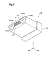
- FIG 2 is a perspective view of the ferrule 10 on one side, viewed from obliquely below.
- the ferrule 10 according to the present embodiment includes a light incidence/emission plane 21 formed in a flat surface, and two or more guide portions 40 at the front end 10a.
- the light incidence/emission plane 21 extends in an X direction (first direction) and a Y direction (second direction), and passes light entering and emitted from the optical fibers F2 (refer to FIG 3 ) constituting the optical fiber bundle F1.
- the light incidence/emission plane 21 faces the light incidence/emission plane 21 of the ferrule 10 on the other side.
- N On the light incidence%mission plane 21, (N ⁇ M) lenses 31 are arranged.
- N is an integer of 2 or more
- M is an integer of 1 or more.
- a line of the lenses formed of the N lenses 31 aligned in the X direction is arranged in one or a plurality of stages in the Y direction.
- the number of stages of the lenses 31 in the Y direction is smaller than the number of lenses 31 aligned in the X direction. That is, N is larger than M.
- the lens 31 is, for example, a GRIN lens embedded in the ferrule 10.
- the GRIN lens is a Graded Index (GI) fiber formed such that a refractive index is gradually decreased from a center to an outer periphery.
- GI Graded Index
- the two or more guide portions 40 determine a relative position with the ferrule 10 on the other side in the X direction and the Y direction.
- the four guide portions 40 are arranged at four corners of the front end 10a.
- the two or more guide portions 40 include a first guide portion 41 and a second guide portion 42 connectable to the first guide portion 41 of the ferrule 10 on the other side.
- the first guide portion 41 is a guide pin protruded from the light incidence/emission plane 21 in the Z direction, for example.
- the second guide portion 42 is, for example, a guide hole formed on the light incidence/emission plane 21 and configured to be fitted with the guide pin of the ferrule 10 on the other side. Note that arrangement of the first guide portion 41 and the second guide portion 42 will be described later in detail.
- FIG 3 is a diagram to describe optical axes in the pair of ferrules 10 and schematically illustrating sectional side view of the ferrules 10 along a YZ plane.
- the pair of ferrules 10 faces each other in a state that one of the ferrules is vertically inverted relative to the other.
- Each of the ferrules 10 includes a plurality of holding holes 16 (holding portions) to hold optical fibers F2 (optical waveguide members).
- the optical fiber F2 may be any one of a single-mode fiber and a multi-mode fiber.
- the plurality of holding holes 16 is formed in an array same as the plurality of lenses 31 illustrated in FIG 2 .
- the plurality of holding holes 16 is arranged such that N holding holes are aligned in the X direction, and further arranged in one or a plurality of stages in the Y direction.
- the plurality of holding holes 16 provides a first optical axis L1 extending in the Z-direction by holding the optical fibers F2. Note that the first optical axis L1 coincides with an optical axis of a core of the optical fiber F2.
- the plurality of lenses 31 is disposed on an optical axis between the respective plural holding holes 16 and the light incidence/emission plane 21.
- an optical axis of the lens 31 (center axis line) is slightly deviated in the Y direction from the first optical axis L1.
- an optical axis of light which enters or is emitted from the optical fiber F2 is slightly curved due to refractive index distribution inside the lens 31. Further, the light is more curved at a boundary face (light incidence/emission plane 21) between the lens 31 and air.
- a second optical axis L2 between the light incidence/emission plane 21 of the ferrule 10 on one side and the light incidence/emission plane 21 of the ferrule 10 on the other side is inclined in the Y direction relative to the Z direction.
- the light emitted from the optical fiber F2 of the ferrule 10 on one side along the first optical axis L1 is directed along the second optical axis L2 after being paralleled (collimated) by the lens 31 of the ferrule 10, and then concentrated by the lens 31 of the ferrule 10 on the other side to enter the optical fiber F2 of the ferrule 10.
- FIGS. 4A and 4B are front views illustrating the pair of ferrules 10, respectively viewed from the front end 10a side.
- FIG 4A illustrates the front end 10a of the ferrule 10 on one side
- FIG 4B illustrates the front end 10a of the ferrule 10 on the other side.
- a positional relation between the two or more guide portions 40 in the ferrule 10 is 180-degree rotationally symmetric around a reference axial line A1 extending in the Z direction.
- the ferrule 10 of the present embodiment includes two of the first guide portions 41 and two of the second guide portions 42, and one of the first guide portions 41 and one of the second guide portions 42 are 180-degree rotationally symmetric around the reference axial line A1, and the other one of the first guide portions 41 and the other one of the second guide portions 42 are 180-degree rotationally symmetric around the reference axial line A1.
- the positional relation between the first guide portion 41 and the second guide portion 42 is line-symmetric relative to a straight line A2 crossing with the reference axial line A1 and parallel to the X direction.
- the reference axial line A1 is a center axis line of the ferrule 10 formed in the Z-direction, and passes through a center point between the two or more guide portions 40.
- one of the first guide portions 41 and one of the second guide portions 42 are disposed close to one end of the front end 10a in the X direction, and the other one of the first guide portions 41 and the other one of the second guide portions 42 are disposed close to the other end of the front end 10a in the X direction. Further, the two first guide portions 41 are disposed close to one end of the front end 10a in the Y direction, and the two second guide portions 42 are disposed close to the other end of the front end 10a in the Y direction.
- the plurality of lenses 31 is disposed disproportionately (asymmetric relative to the straight line A2) in a direction opposite to an inclination direction of the second optical axis L2 (negative direction in a Y axis at the ferrule 10 on one side, and positive direction in the Y axis at the ferrule 10 on the other side) from a position line-symmetric relative to the straight line A2.
- the plurality of lenses 31 is arranged line-symmetric relative to a straight line A3 parallel to the X direction, and the straight line A3 is offset in the Y direction by a distance H1 relative to the straight line A2 which is a symmetric line of the guide portions 40.
- each of the plurality of lenses 31 of the ferrule 10 on one side is suitably optically connected to each of the plurality of lenses 31 of the ferrule 10 on the other side via the inclined second optical axis L2.
- FIG 5 is a diagram illustrating an offset amount of the plurality of lenses 31 in the Y direction, namely, a calculation method for the offset amount of the first optical axis L1 in the Y direction.
- a distance between the lens 31 of the ferrule 10 on one side and the lens 31 of the ferrule 10 on the other side when the pair of ferrules 10 is connected facing each other is defined as 2d
- an angle formed between the first optical axis L1 and the second optical axis L2 (before refraction between the optical fiber F2 and the lens 31) is defined as ⁇ .
- the second optical axis L2 between the light incidence/emission plane 21 and the ferrule 10 on the other side is inclined relative to the first optical axis L1 (i.e., optical axis of the optical fiber F2) provided by the holding hole 16 which holds the optical fiber F2.
- the first optical axis L1 i.e., optical axis of the optical fiber F2
- the holding hole 16 which holds the optical fiber F2.
- the positional relation between the two or more guide portions 40 is 180-degree rotationally symmetric around the reference axial line A1, and further the plurality of lenses 31 is arranged disproportionately in a direction opposite to the inclination direction of the second optical axis L2 from the position line-symmetric relative to the straight line A2.
- the plurality of lenses 31 is asymmetrically arranged relative to the straight line A2.
- the two or more guide portion 40 include the first guide portion 41 and the second guide portion 42, and the positional relation therebetween is preferably 180-degree rotationally symmetric around the reference axial line A1.
- the pair of ferrules 10 is stably fixed each other, thereby achieving to provide a highly reliable connector fitting structure.
- the positional relation between the first guide portion 41 and the second guide portion 42 is line-symmetric relative to the straight line A2 as illustrated in FIG. 4 .
- the ferrules 10 can be suitably connected to each other by vertically inverting one of the ferrules 10 having the same shape and making the ferrules face each other. Therefore, the shape of the ferrules 10 can be standardized, and cost for the connector fitting structure can be reduced.
- FIGS. 6A and 6B are diagrams illustrating a structure of an optical connection structure according to a first modified example of the above-described embodiment
- FIG. 6A is a front view of the ferrule 10A on one side
- FIG 6B is a front view of the ferrule 10A on the other side, viewed from the front end 10a side.
- FIG 6B illustrates the ferrule 10A vertically inverted.
- a difference between the ferrule 10A of the present modified example and the ferrule 10 of the above-described embodiment is a structure of the guide portion.
- the positional relation between the two guide portions 40 in the present modified example is 180-degree rotationally symmetric around the reference axial line A1, and further when viewed in the Z direction, the guide portions are respectively disposed on the straight line A2. More specifically, one of the guide portions 40 is disposed close to one side of the straight line A2 at the front end 10a, and the other guide portions 40 is disposed closed to the other side of the straight line A2 at the front end 10a. Further, according to the present modified example, the two guide portions 40 are all formed of long holes 43 for inserting the guide pins each having a round bar shape, instead of the first guide portion 41 and the second guide portion 42 described in the above embodiment. A center axis line of the long hole 43 extends along the Z-direction. Note that the guide pin is prepared separately from the ferrule 10A.
- the ferrules 10A can also be connected in a state that the respective center axis lines of the pair of the ferrules 10A are made to coincide with each other and also the ferrule 10A on the other side is vertically inverted.
- the ferrules 10A mutually having the same shape can be suitably connected even when the second optical axis L2 between the ferrules 10A is inclined.
- the pair of the ferrules 10A is stably fixed each other by the guide portions 40 being disposed at the center of the ferrule 10A in the Y direction like the present modified example, thereby achieving to provide a highly reliable connector fitting structure.
- FIGS. 7A and 7B are diagrams illustrating a structure of an optical connection structure according to a second modified example of the above-described embodiment
- FIG 7A is a front view of the ferrule 10B on one side
- FIG 7B is a front view of the ferrule 10C on the other side, viewed from the front end 10a side.
- a difference between the ferrules 10B, 10C of the present modified example and the ferrule 10 of the above-described embodiment is a structure of the guide portion.
- the positional relation between the two guide portions 40 according to the present modified example is 180-degree rotationally symmetric around the reference axial line A1, and further the guide portions 40 are disposed on the straight line A2 when viewed in the Z direction.
- One of the two guide portions 40 is the first guide portion 41, and the other is the second guide portion 42. More specifically, the first guide portion 41 is disposed close to one end of the straight line A2 at the front end 10a, and the second guide portion 42 is disposed close to the other end of the straight line A2 at the front end 10a.
- FIG 7B illustrates a state in which the ferrule 10C is vertically inverted.
- a plurality of lenses 31 of the ferrule 10B and a plurality of lenses 31 of the ferrule 10C are optically connected to each other via the inclined second optical axis L2.
- a positional relation between the first guide portion 41 and the second guide portion 42 is reversed between the ferrule 10B and the ferrule 10C.
- the ferrule 10B and the ferrule 10C cannot have the same shape.
- the pair of ferrules 10B and 10C is stably fixed each other by the guide portions 40 being disposed at the center of the ferrule 10B in the Y direction, thereby achieving to provide a highly reliable connector fitting structure.
- the guide pin is not needed to be prepared separately unlike the first modified example, the number of components can be reduced and cost reduction can be achieved.
- FIGS. 8A and 8B are diagrams illustrating a structure of an optical connection structure according to a third modified example of the above-described embodiment
- FIG. 8A is a front view of the ferrule 10D on one side
- FIG 8B is a front view of the ferrule 10E on the other side, viewed from the front end 10a side.
- a difference between the ferrules 10D, 10E of the present modified example and the ferrules 10B, 10C of the above-described second modified example is a structure of the guide portion.
- the positional relation between the two guide portions 40 according to the present modified example is 180-degree rotationally symmetric around the reference axial line A1, and further the guide portions are not disposed on the straight line A2 when viewed in the Z direction. More specifically, the first guide portion 41 is disposed close to one end of a diagonal line at the front end 10a, and the second guide portion 42 is disposed close to the other of the diagonal line at the front end 10a.
- the plurality of lenses 31 of the ferrule 10D and the plurality of lenses 31 of the ferrule 10E are optically connected to each other via the inclined second optical axis L2 by vertically inverting the ferrule 10E. Therefore, in order that the first guide portion 41 of the ferrule 10D and the second guide portion 42 of the ferrule 10E are mutually fitted and also the second guide portion 42 of the ferrule 10D and the first guide portion 41 of the ferrule 10E are mutually fitted, a positional relation between the first guide portion 41 and the second guide portion 42 is reversed between the ferrule 10D and the ferrule 10E.
- the ferrule 10D and the ferrule 10E cannot have the same shape each other.
- the pair of ferrules 10D, 10E is stably fixed each other, thereby achieving to provide a highly reliable connector fitting structure. Further, since the guide pin is not needed to be prepared separately unlike the first modified example, the number of components can be reduced and cost reduction can be achieved.
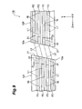
- FIG 9 is a diagram illustrating a structure of an optical connection structure 1B according to a fourth modified example of the above-described embodiment and schematically illustrating a sectional side view of ferrules 10F along the YZ plane in order to describe optical axes in a pair of ferrules 10F.
- the optical connection structure 1B includes the pair of the ferrules 10F mutually connected.
- a difference between the ferrule 10F of the present modified example and the above-described embodiment is a structure to incline the second optical axis L2.
- the light incidence/emission plane 21 at the front end 10a is inclined in the Y direction relative to a flat surface vertical to the first optical axis L1 provided by the holding hole 16. Further, the first optical axis L1 and the optical axis of the lens 31 coincide with each other. With this structure, the first optical axis L1 is kept inside the lens 31, and the second optical axis L2 inclined relative to the Z direction is provided by refraction at the light incidence/emission plane 21.
- the ferrule 10F is suitably manufactured by, for example, inserting and fixing the lens 31 into a hole formed at the light incidence/emission plane 21 of a ferrule main body and diagonally polishing an end surface of the lens 31 along with the light incidence/emission plane 21.
- the light incidence/emission plane 21 is inclined and a length of the lens 31 is constant. Therefore, positions of tip surfaces of the optical fibers F2 are gradually deviated along the inclination of the light incidence%mission plane 21.
- a tip surface of an optical fiber F2 at an n th stage counted from one end 10d side of the ferrule 10F in the Y direction is deviated in the Z direction from a tip surface of an optical fiber F2 at an (n - 1) th stage by a distance Z1.
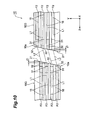
- FIG 10 is a diagram illustrating a structure in which the optical connection structure 1B in FIG. 9 is more improved.
- An optical connection structure 1C illustrated in FIG 10 includes a pair of ferrules 10G mutually connected.
- a coreless fiber 32 is disposed between the lens 31 and the light incidence/emission plane 21.
- the coreless fiber 32 keeps the light in the lens 31 in a paralleled state. Further, a length of the coreless fiber 32 in the Z direction becomes gradually longer along the inclination of the light incidence/emission plane 21.
- the length of the coreless fiber 32 at an n th stage counted from one end 10d side of the ferrule 10G in the Y direction is longer than the length of the coreless fiber 32 at a (n - 1) th stage by a length Z1.
- the positions of the tip surfaces of the optical fibers F2 in the respective stages can be aligned same as the first embodiment.
- the ferrule 10G can be suitably manufactured by, for example, inserting and fixing the lens 31 and the coreless fiber 32 into a hole formed at the light incidence/emission plane 21 of the ferrule main body and diagonally polishing an end surface of the coreless fiber 32 along with the light incidence/emission plane 21.
- the optical connection structure in which the second optical axis L2 is inclined relative to the Z direction can be achieved with a simple structure.
- the number of stages of the holding holes 16 in the Y direction (i.e., number of lenses 31) M is preferably smaller than the number of holding holes 16 aligned in the X direction (i.e., number of lenses 31) N.
- the light incidence%mission plane 21 is preferably inclined in a short direction in the array of the plurality of lenses 31.
- FIGS. 11A and 11B are diagrams schematically illustrating sectional side views of a ferrule according to a second embodiment of the present invention.
- a ferrule 10H illustrated in FIG 11A includes a ferrule main body 17 and a lens array 18 set at one end of the ferrule main body 17 in a Z direction. Note that the ferrule 10H includes a guide portion same as a first embodiment or each of modified examples, but illustration thereof is omitted here.
- the ferrule main body 17 includes a plurality of holding holes 16 to hold a plurality of optical fibers F2. Arrays of the optical fibers F2 and the holding holes 16 in an X direction and a Y direction are same as the first embodiment.
- the plurality of holding holes 16 reaches to a front end surface 17a of the ferrule main body 17, and tip surfaces of the plurality of the optical fibers F2 are exposed from the front end surface 17a.
- the lens array 18 includes a rear surface 18a facing the front end surface 17a of the ferrule main body 17, and a light incidence/emission plane 18b on an opposite side of the rear surface 18a.
- the light incidence%mission plane 18b extends in the X direction and the Y direction, and is orthogonal to a first optical axis L1, for example.
- the light incidence%mission plane passes light entering and emitted from each of the optical fibers F2.
- the light incidence/emission plane 18b faces a light incidence/emission plane 18b of a ferrule 10H on the other side.
- a plurality of lenses 33 is disposed at the rear surface 18a. Arrays of the lenses 33 in the X direction and the Y direction are same as the first embodiment.
- the lens 33 is, for example, a convex lens disposed at the rear surface 18a and preferably integrally formed with the lens array 18. Further, each of the plurality of lenses 33 and each of the plurality of optical fibers F2 are optically connected to each other by a suitable positioning structure provided at the lens array 18.
- optical axes of the respective lenses 33 are slightly deviated in the Y direction relative to the first optical axes L1 provided by the holding holes 16 that hold corresponding optical fibers F2.
- the optical axis of the light entering or emitted from the optical fiber F2 is curved at the lens 33. Therefore, a second optical axis L2 between the lens 33 of the ferrule 10H on one side and the lens 33 of the ferrule 10H on the other side is inclined in the Y direction relative to the Z direction.
- the light emitted from the optical fiber F2 of the ferrule 10H on one side along the first optical axis L1 is directed along the second optical axis L2 after being paralleled (collimated) by the lens 33 of the ferrule 10H, and passes through the light incidence/emission planes 18b on the both ferrules to enter the optical fiber F2 of the ferrule 10H on the other side while being concentrated by the lens 33 of the ferrule 10H on the other side.
- a ferrule 10J illustrated in FIG 11B has the same structure as a ferrule 10H illustrated in FIG. 11A except for following points.
- the first optical axis L1 provided by each of the plurality of holding holes 16 and an optical axis of each of the plurality of lenses 33 coincide with each other. Therefore, an optical axis between the light incidence/emission plane 18b and the lens 33 coincides with the first optical axis L1.
- the light incidence/emission plane 18b is inclined in the Y direction relative to a flat surface vertical to the first optical axis L1. With this structure, refraction is generated at the light incidence/emission plane 18b and the second optical axis L2 inclined in the Z direction is provided.
- the lens 33 which is the convex lens is disposed at the rear surface 18a.
- the light incidence/emission plane 18b can be formed flat and cleaning for the light incidence/emission plane 18b is facilitated compared to the case where the convex lens is provided at the light incidence%mission plane.
- the optical axes of the lens 33 coincides with the optical axis of the optical fiber F2. Therefore, a center portion of the lens 33 is efficiently used and the lens 33 can be downsized compared to the ferrule 10H illustrated in FIG. 11A .
- FIG. 12 is a diagram illustrating a structure of an optical connection structure 1D according to a third embodiment of the present invention, and a schematic view of a cross-sectional surface taken along an XZ plane.
- This optical connection structure 1D includes a pair of ferrules 10K mutually connected.
- a difference between the ferrule 10K of the present embodiment and a ferrule 10 of a first embodiment (refer to FIG 3 ) is an inclination direction of a second optical axis L2.
- the second optical axis L2 of the present embodiment is inclined in an X direction relative to a Z direction.
- optical axes (center axis lines) of respective plural lenses 31 are slightly deviated in the X direction from first optical axes L1 provided by a plurality of holding holes 16.
- an optical axis of light which enters or is emitted from the optical fiber F2 is slightly curved due to refractive index distribution inside the lens 31. Further, the light is more curved at a boundary face (light incidence/emission plane 21) between the lens 31 and air.
- the second optical axis L2 between the light incidence/emission plane 21 of the ferrule 10K on one side and the light incidence/emission plane 21 of the ferrule 10K on the other side is inclined in the X direction relative to the Z direction.
- FIGS. 13A and 13B are front views of a pair of the ferrules 10K, respectively viewed from a front end 10a side.
- FIG 13A illustrates the front end 10a of the ferrule 10K on one side
- FIG. 13B illustrates the front end 10a of the ferrule 10K on the other side horizontally inverted.
- a positional relation between two guide portions 40 in the ferrule 10K is 180-degree rotationally symmetric around a reference axial line A1 extending in the Z direction, and the two guide portions 40 are respectively disposed on a straight line A2 when viewed in the Z direction.
- the ferrule 10K of the present embodiment includes one first guide portion 41 and one second guide portion 42, and these guide portions are 180-degree rotationally symmetric around the reference axial line A1. More specifically, the first guide portion 41 is disposed close to one end of the straight line A2 at the front end 10a, and the second guide portion 42 is disposed close to the other end of the straight line A2 at the front end 10a.
- the plurality of lenses 31 is disposed disproportionately (asymmetric relative a straight line A5) in a direction opposite to the inclination direction of the second optical axis L2 (negative direction in an X axis at the ferrule 10K on one side, and positive direction in the X axis at the ferrule 10K on the other side) from a position line-symmetric relative to the straight line A5 crossing with the reference axial line A1 and parallel to the Y direction.
- the plurality of lenses 31 is disposed line-symmetric relative to a straight line A6 parallel to the Y direction, and the straight line A6 is offset in the X direction by a distance H2 relative to the straight line A5 which is a symmetric line of the guide portions 40.
- each of the plurality of lenses 31 of the ferrule 10K on one side is suitably optically connected to each of the plurality of lenses 31 of the ferrule 10K on the other side via the inclined second optical axis L2.
- the ferrules 10K of the above-described present embodiment effects same as the first embodiment can be obtained. Further, the ferrules 10K can be connected in a state that the respective center axis lines of the pair of the ferrules 10K are made to coincide with each other without vertically inverting the ferrule 10K on the other side.
- the ferrules 10K mutually having the same shape can be suitably connected even when the second optical axis L2 between the ferrules 10K is inclined. Further, the pair of ferrules 10K is stably fixed each other, thereby achieving to provide a highly reliable connector fitting structure.
- an unused region (dead space) 10e at the front end 10a caused by offsetting the plurality of lenses 31 is minimized, thereby achieving to improve area use efficiency at the front end 10a.
- the area of the unused region is obtained by multiplying an offset distance by N because a plurality of lenses 31 is offset in a direction (Y direction) vertical to a direction in which N lenses 31 are arrayed.
- the area of the unused region 10e obtained by multiplying an offset distance by M is smaller than the first embodiment because the plurality of lenses 31 is offset in a direction (X direction) vertical to a direction in which M lenses 31 fewer than N lenses are arrayed.
- FIGS. 14A and 14B are diagrams illustrating a structure of an optical connection structure according to a fifth modified example of the above-described embodiment
- FIG. 14A is a front view of a ferrule 10L on one side
- FIG 14B is a front view of the ferrule 10L on the other side, viewed from a front end 10a side.
- FIG 14B illustrates the ferrule 10L horizontally inverted.
- a difference between the ferrule 10L of the present modified example and the ferrule 10K of the above-described embodiment is a structure of the guide portion.
- the two guide portions 40 according to the present modified example are all formed of long holes 43 for inserting guide pins each having a round bar shape, instead of the first guide portion 41 and the second guide portion 42 described in the above embodiment.
- a center axis line of the long hole 43 extends along the Z-direction. Note that the guide pin is prepared separately from the ferrule 10L.
- the ferrules 10L can be connected in a state that the respective center axis lines of the pair of the ferrules 10L are made to coincide with each other and further the ferrule 10L on the other side is horizontally inverted.
- the ferrules 10L mutually having the same shape can be suitably connected even when the second optical axis L2 between the ferrules 10L is inclined.
- the pair of the ferrules 10L is stably fixed each other by the guide portions 40 being disposed at the center of the ferrule 10L in the Y direction like the present modified example, thereby achieving to provide a highly reliable connector fitting structure.
Landscapes
- Physics & Mathematics (AREA)
- General Physics & Mathematics (AREA)
- Optics & Photonics (AREA)
- Optical Couplings Of Light Guides (AREA)
- Mechanical Coupling Of Light Guides (AREA)
Applications Claiming Priority (1)
| Application Number | Priority Date | Filing Date | Title |
|---|---|---|---|
| JP2014189829A JP6459334B2 (ja) | 2014-09-18 | 2014-09-18 | フェルール及び光接続構造 |
Publications (2)
| Publication Number | Publication Date |
|---|---|
| EP2998771A1 true EP2998771A1 (fr) | 2016-03-23 |
| EP2998771B1 EP2998771B1 (fr) | 2018-10-24 |
Family
ID=54140349
Family Applications (1)
| Application Number | Title | Priority Date | Filing Date |
|---|---|---|---|
| EP15185012.0A Active EP2998771B1 (fr) | 2014-09-18 | 2015-09-14 | Ferrule |
Country Status (5)
| Country | Link |
|---|---|
| US (1) | US9360632B2 (fr) |
| EP (1) | EP2998771B1 (fr) |
| JP (1) | JP6459334B2 (fr) |
| CN (1) | CN105445866B (fr) |
| TW (1) | TWI665482B (fr) |
Cited By (4)
| Publication number | Priority date | Publication date | Assignee | Title |
|---|---|---|---|---|
| WO2018164954A1 (fr) * | 2017-03-07 | 2018-09-13 | Corning Optical Communications LLC | Ferrules de fibre optique incorporant une plaque frontale de verre et leurs procédés de fabrication |
| EP3327475A4 (fr) * | 2015-07-22 | 2019-02-27 | Toyo Seikan Group Holdings, Ltd. | Connecteur pour fibres optiques comprenant des lentilles |
| EP3470897A4 (fr) * | 2016-06-10 | 2020-01-15 | Toyo Seikan Group Holdings, Ltd. | Connecteur optique à âmes multiples et son procédé de fabrication |
| US11579369B2 (en) | 2017-12-21 | 2023-02-14 | Sony Corporation | Optical communication connector, optical communication cable, and electronic device |
Families Citing this family (8)
| Publication number | Priority date | Publication date | Assignee | Title |
|---|---|---|---|---|
| US10197743B2 (en) | 2015-05-22 | 2019-02-05 | US Conec, Ltd | Multi-fiber ferrule with improved eye safety |
| JP2017173539A (ja) * | 2016-03-23 | 2017-09-28 | 住友電気工業株式会社 | 光コネクタ及び光結合構造 |
| JPWO2017195636A1 (ja) * | 2016-05-12 | 2019-03-14 | 住友電気工業株式会社 | 光コネクタ及び光結合構造 |
| TWI731128B (zh) * | 2016-08-10 | 2021-06-21 | 日商索尼股份有限公司 | 光連接器、光纜線及電子機器 |
| JP6763234B2 (ja) * | 2016-08-18 | 2020-09-30 | 住友電気工業株式会社 | 光コネクタフェルール、光コネクタ、アダプタ、及び光接続構造 |
| CN110692002B (zh) * | 2017-06-02 | 2021-11-05 | 古河电气工业株式会社 | 光连接器以及光连接器连接结构 |
| CN112219144B (zh) * | 2018-06-05 | 2022-07-22 | 住友电气工业株式会社 | 光连接器插芯的制造方法及光连接器插芯 |
| US12222557B2 (en) * | 2020-01-24 | 2025-02-11 | Us Conec Ltd. | Ferrule with molded internal tilted refractive surfaces |
Citations (6)
| Publication number | Priority date | Publication date | Assignee | Title |
|---|---|---|---|---|
| US5214730A (en) * | 1991-05-13 | 1993-05-25 | Nippon Telegraph And Telephone Corporation | Multifiber optical connector plug with low reflection and low insertion loss |
| US5832153A (en) * | 1996-06-20 | 1998-11-03 | Duck; Gary Stephen | Method and system for reducing unwanted effects of back reflections between two lenses in an optical system |
| US5845028A (en) * | 1996-03-12 | 1998-12-01 | Minnesota Mining And Manufacturing Company | Alignment assembly for multifiber or single fiber optical cable connector |
| US6012852A (en) * | 1996-12-18 | 2000-01-11 | The Whitaker Corporation | Expanded beam fiber optic connector |
| JP2008151843A (ja) | 2006-12-14 | 2008-07-03 | Omron Corp | 光伝送用光学部品及びその製造方法 |
| WO2013019622A2 (fr) * | 2011-07-29 | 2013-02-07 | Molex Incorporated | Ferrule multifibre à plaque de lentille |
Family Cites Families (16)
| Publication number | Priority date | Publication date | Assignee | Title |
|---|---|---|---|---|
| JPS57110520U (fr) * | 1980-12-27 | 1982-07-08 | ||
| DE68921207T2 (de) * | 1989-09-27 | 1995-09-07 | Hewlett Packard Gmbh | Verfahren zur Herstellung eines faseroptischen Steckers. |
| US6044187A (en) * | 1998-04-01 | 2000-03-28 | Duck; Gary S. | Multi-port fiber optical device |
| JP2003248142A (ja) * | 2001-07-12 | 2003-09-05 | Ngk Insulators Ltd | 二次元光学部材アレイ及び二次元導波路装置 |
| JP2003337244A (ja) * | 2002-05-20 | 2003-11-28 | Sumitomo Electric Ind Ltd | 光ファイバ位置決めユニット及び光ファイバアレイ |
| JP2005037731A (ja) * | 2003-07-16 | 2005-02-10 | Nippon Telegr & Teleph Corp <Ntt> | 光コネクタ |
| JP2005309009A (ja) * | 2004-04-20 | 2005-11-04 | Furukawa Electric Co Ltd:The | 多心多段光コネクタ用フェルール及びこれを用いた多心多段光コネクタ。 |
| JP4925323B2 (ja) * | 2007-08-21 | 2012-04-25 | 東洋ガラス株式会社 | 光ファイバコリメータ及び光ファイバコリメータアレイの製造方法 |
| JP2010026175A (ja) * | 2008-07-17 | 2010-02-04 | Fujikura Ltd | 光ファイバコリメータアレイ |
| JP5823198B2 (ja) * | 2011-07-15 | 2015-11-25 | 北日本電線株式会社 | フォトモジュール |
| JP5851794B2 (ja) * | 2011-10-21 | 2016-02-03 | 株式会社フジクラ | 光軸合わせ方法及び光ファイバアレイユニットの製造方法 |
| JP2013171208A (ja) * | 2012-02-21 | 2013-09-02 | Fujitsu Ltd | 光コネクタ、光接続構造、及び光コネクタの製造方法 |
| US8814442B2 (en) * | 2012-03-07 | 2014-08-26 | Verizon Patent And Licensing Inc. | Hardened multiport optical connector assembly |
| US9022669B2 (en) * | 2012-12-21 | 2015-05-05 | Corning Cable Systems Llc | Gradient index lens assemblies, fiber optic connectors, and fiber optic cable assemblies employing lens alignment channels |
| JP6029115B2 (ja) * | 2014-03-26 | 2016-11-24 | インターナショナル・ビジネス・マシーンズ・コーポレーションInternational Business Machines Corporation | 光デバイス、光コネクタ・アセンブリおよび光接続方法 |
| JP6379898B2 (ja) * | 2014-09-11 | 2018-08-29 | 住友電気工業株式会社 | 光コネクタ、及び、光コネクタの製造方法 |
-
2014
- 2014-09-18 JP JP2014189829A patent/JP6459334B2/ja active Active
-
2015
- 2015-09-11 TW TW104130186A patent/TWI665482B/zh active
- 2015-09-14 EP EP15185012.0A patent/EP2998771B1/fr active Active
- 2015-09-15 US US14/854,188 patent/US9360632B2/en active Active
- 2015-09-18 CN CN201510599704.XA patent/CN105445866B/zh active Active
Patent Citations (6)
| Publication number | Priority date | Publication date | Assignee | Title |
|---|---|---|---|---|
| US5214730A (en) * | 1991-05-13 | 1993-05-25 | Nippon Telegraph And Telephone Corporation | Multifiber optical connector plug with low reflection and low insertion loss |
| US5845028A (en) * | 1996-03-12 | 1998-12-01 | Minnesota Mining And Manufacturing Company | Alignment assembly for multifiber or single fiber optical cable connector |
| US5832153A (en) * | 1996-06-20 | 1998-11-03 | Duck; Gary Stephen | Method and system for reducing unwanted effects of back reflections between two lenses in an optical system |
| US6012852A (en) * | 1996-12-18 | 2000-01-11 | The Whitaker Corporation | Expanded beam fiber optic connector |
| JP2008151843A (ja) | 2006-12-14 | 2008-07-03 | Omron Corp | 光伝送用光学部品及びその製造方法 |
| WO2013019622A2 (fr) * | 2011-07-29 | 2013-02-07 | Molex Incorporated | Ferrule multifibre à plaque de lentille |
Cited By (4)
| Publication number | Priority date | Publication date | Assignee | Title |
|---|---|---|---|---|
| EP3327475A4 (fr) * | 2015-07-22 | 2019-02-27 | Toyo Seikan Group Holdings, Ltd. | Connecteur pour fibres optiques comprenant des lentilles |
| EP3470897A4 (fr) * | 2016-06-10 | 2020-01-15 | Toyo Seikan Group Holdings, Ltd. | Connecteur optique à âmes multiples et son procédé de fabrication |
| WO2018164954A1 (fr) * | 2017-03-07 | 2018-09-13 | Corning Optical Communications LLC | Ferrules de fibre optique incorporant une plaque frontale de verre et leurs procédés de fabrication |
| US11579369B2 (en) | 2017-12-21 | 2023-02-14 | Sony Corporation | Optical communication connector, optical communication cable, and electronic device |
Also Published As
| Publication number | Publication date |
|---|---|
| US20160085030A1 (en) | 2016-03-24 |
| US9360632B2 (en) | 2016-06-07 |
| TW201619650A (zh) | 2016-06-01 |
| CN105445866A (zh) | 2016-03-30 |
| CN105445866B (zh) | 2019-01-01 |
| TWI665482B (zh) | 2019-07-11 |
| EP2998771B1 (fr) | 2018-10-24 |
| JP6459334B2 (ja) | 2019-01-30 |
| JP2016061942A (ja) | 2016-04-25 |
Similar Documents
| Publication | Publication Date | Title |
|---|---|---|
| EP2998771B1 (fr) | Ferrule | |
| EP2998770B1 (fr) | Connecteur optique et procédé de fabrication d'un connecteur optique | |
| US9551835B2 (en) | Grin lens array, lens-mounted connector, and lens-mounted connector system | |
| JP6775085B2 (ja) | レンズ素子を有するマルチファイバフェルール | |
| US11054586B2 (en) | Optical connector and optical connection structure | |
| WO2012172906A1 (fr) | Élément de connexion optique, structure de connexion optique et procédé de production d'éléments de connexion optique | |
| US10670814B2 (en) | Optical connector and optical connection structure | |
| US9599776B2 (en) | Optical coupling member | |
| EP3470897A1 (fr) | Connecteur optique à âmes multiples et son procédé de fabrication | |
| JP2016061941A (ja) | 光ファイバ接続構造 | |
| US20170184793A1 (en) | Lens-equipped connector | |
| US10775569B2 (en) | Optical connector and optical connection structure | |
| US20170160491A1 (en) | Eye-safe interface for optical connector | |
| WO2017015279A1 (fr) | Interface sans danger pour l'oeil pour connecteur optique | |
| WO2019200066A1 (fr) | Structure d'alignement pour une ferrule de fibre optique et interface mécanique-optique | |
| JP2016061944A (ja) | ファンアウト部品 | |
| EP4571375A1 (fr) | Fibre à âmes multiples, dispositif optique et ensemble fibre à âmes multiples | |
| CN104272152A (zh) | 具有扩展光束的多模态多芯光纤连接 | |
| CN2557964Y (zh) | 多光路准直装置 | |
| JP2016057483A (ja) | コネクタフェルール | |
| JP2013020229A (ja) | 光接続部材及び光接続構造 |
Legal Events
| Date | Code | Title | Description |
|---|---|---|---|
| PUAI | Public reference made under article 153(3) epc to a published international application that has entered the european phase |
Free format text: ORIGINAL CODE: 0009012 |
|
| AK | Designated contracting states |
Kind code of ref document: A1 Designated state(s): AL AT BE BG CH CY CZ DE DK EE ES FI FR GB GR HR HU IE IS IT LI LT LU LV MC MK MT NL NO PL PT RO RS SE SI SK SM TR |
|
| AX | Request for extension of the european patent |
Extension state: BA ME |
|
| 17P | Request for examination filed |
Effective date: 20160712 |
|
| RBV | Designated contracting states (corrected) |
Designated state(s): AL AT BE BG CH CY CZ DE DK EE ES FI FR GB GR HR HU IE IS IT LI LT LU LV MC MK MT NL NO PL PT RO RS SE SI SK SM TR |
|
| STAA | Information on the status of an ep patent application or granted ep patent |
Free format text: STATUS: EXAMINATION IS IN PROGRESS |
|
| 17Q | First examination report despatched |
Effective date: 20170616 |
|
| GRAP | Despatch of communication of intention to grant a patent |
Free format text: ORIGINAL CODE: EPIDOSNIGR1 |
|
| STAA | Information on the status of an ep patent application or granted ep patent |
Free format text: STATUS: GRANT OF PATENT IS INTENDED |
|
| INTG | Intention to grant announced |
Effective date: 20180703 |
|
| GRAS | Grant fee paid |
Free format text: ORIGINAL CODE: EPIDOSNIGR3 |
|
| GRAA | (expected) grant |
Free format text: ORIGINAL CODE: 0009210 |
|
| STAA | Information on the status of an ep patent application or granted ep patent |
Free format text: STATUS: THE PATENT HAS BEEN GRANTED |
|
| AK | Designated contracting states |
Kind code of ref document: B1 Designated state(s): AL AT BE BG CH CY CZ DE DK EE ES FI FR GB GR HR HU IE IS IT LI LT LU LV MC MK MT NL NO PL PT RO RS SE SI SK SM TR |
|
| REG | Reference to a national code |
Ref country code: CH Ref legal event code: EP |
|
| REG | Reference to a national code |
Ref country code: IE Ref legal event code: FG4D |
|
| REG | Reference to a national code |
Ref country code: AT Ref legal event code: REF Ref document number: 1057353 Country of ref document: AT Kind code of ref document: T Effective date: 20181115 |
|
| REG | Reference to a national code |
Ref country code: DE Ref legal event code: R096 Ref document number: 602015018602 Country of ref document: DE |
|
| REG | Reference to a national code |
Ref country code: SE Ref legal event code: TRGR |
|
| REG | Reference to a national code |
Ref country code: NL Ref legal event code: MP Effective date: 20181024 |
|
| REG | Reference to a national code |
Ref country code: CH Ref legal event code: NV Representative=s name: NOVAGRAAF INTERNATIONAL SA, CH |
|
| REG | Reference to a national code |
Ref country code: LT Ref legal event code: MG4D |
|
| REG | Reference to a national code |
Ref country code: AT Ref legal event code: MK05 Ref document number: 1057353 Country of ref document: AT Kind code of ref document: T Effective date: 20181024 |
|
| PG25 | Lapsed in a contracting state [announced via postgrant information from national office to epo] |
Ref country code: NL Free format text: LAPSE BECAUSE OF FAILURE TO SUBMIT A TRANSLATION OF THE DESCRIPTION OR TO PAY THE FEE WITHIN THE PRESCRIBED TIME-LIMIT Effective date: 20181024 |
|
| PG25 | Lapsed in a contracting state [announced via postgrant information from national office to epo] |
Ref country code: IS Free format text: LAPSE BECAUSE OF FAILURE TO SUBMIT A TRANSLATION OF THE DESCRIPTION OR TO PAY THE FEE WITHIN THE PRESCRIBED TIME-LIMIT Effective date: 20190224 Ref country code: FI Free format text: LAPSE BECAUSE OF FAILURE TO SUBMIT A TRANSLATION OF THE DESCRIPTION OR TO PAY THE FEE WITHIN THE PRESCRIBED TIME-LIMIT Effective date: 20181024 Ref country code: BG Free format text: LAPSE BECAUSE OF FAILURE TO SUBMIT A TRANSLATION OF THE DESCRIPTION OR TO PAY THE FEE WITHIN THE PRESCRIBED TIME-LIMIT Effective date: 20190124 Ref country code: PL Free format text: LAPSE BECAUSE OF FAILURE TO SUBMIT A TRANSLATION OF THE DESCRIPTION OR TO PAY THE FEE WITHIN THE PRESCRIBED TIME-LIMIT Effective date: 20181024 Ref country code: HR Free format text: LAPSE BECAUSE OF FAILURE TO SUBMIT A TRANSLATION OF THE DESCRIPTION OR TO PAY THE FEE WITHIN THE PRESCRIBED TIME-LIMIT Effective date: 20181024 Ref country code: AT Free format text: LAPSE BECAUSE OF FAILURE TO SUBMIT A TRANSLATION OF THE DESCRIPTION OR TO PAY THE FEE WITHIN THE PRESCRIBED TIME-LIMIT Effective date: 20181024 Ref country code: LV Free format text: LAPSE BECAUSE OF FAILURE TO SUBMIT A TRANSLATION OF THE DESCRIPTION OR TO PAY THE FEE WITHIN THE PRESCRIBED TIME-LIMIT Effective date: 20181024 Ref country code: ES Free format text: LAPSE BECAUSE OF FAILURE TO SUBMIT A TRANSLATION OF THE DESCRIPTION OR TO PAY THE FEE WITHIN THE PRESCRIBED TIME-LIMIT Effective date: 20181024 Ref country code: LT Free format text: LAPSE BECAUSE OF FAILURE TO SUBMIT A TRANSLATION OF THE DESCRIPTION OR TO PAY THE FEE WITHIN THE PRESCRIBED TIME-LIMIT Effective date: 20181024 Ref country code: NO Free format text: LAPSE BECAUSE OF FAILURE TO SUBMIT A TRANSLATION OF THE DESCRIPTION OR TO PAY THE FEE WITHIN THE PRESCRIBED TIME-LIMIT Effective date: 20190124 |
|
| PG25 | Lapsed in a contracting state [announced via postgrant information from national office to epo] |
Ref country code: PT Free format text: LAPSE BECAUSE OF FAILURE TO SUBMIT A TRANSLATION OF THE DESCRIPTION OR TO PAY THE FEE WITHIN THE PRESCRIBED TIME-LIMIT Effective date: 20190224 Ref country code: AL Free format text: LAPSE BECAUSE OF FAILURE TO SUBMIT A TRANSLATION OF THE DESCRIPTION OR TO PAY THE FEE WITHIN THE PRESCRIBED TIME-LIMIT Effective date: 20181024 Ref country code: RS Free format text: LAPSE BECAUSE OF FAILURE TO SUBMIT A TRANSLATION OF THE DESCRIPTION OR TO PAY THE FEE WITHIN THE PRESCRIBED TIME-LIMIT Effective date: 20181024 Ref country code: GR Free format text: LAPSE BECAUSE OF FAILURE TO SUBMIT A TRANSLATION OF THE DESCRIPTION OR TO PAY THE FEE WITHIN THE PRESCRIBED TIME-LIMIT Effective date: 20190125 |
|
| REG | Reference to a national code |
Ref country code: DE Ref legal event code: R097 Ref document number: 602015018602 Country of ref document: DE |
|
| PG25 | Lapsed in a contracting state [announced via postgrant information from national office to epo] |
Ref country code: CZ Free format text: LAPSE BECAUSE OF FAILURE TO SUBMIT A TRANSLATION OF THE DESCRIPTION OR TO PAY THE FEE WITHIN THE PRESCRIBED TIME-LIMIT Effective date: 20181024 Ref country code: IT Free format text: LAPSE BECAUSE OF FAILURE TO SUBMIT A TRANSLATION OF THE DESCRIPTION OR TO PAY THE FEE WITHIN THE PRESCRIBED TIME-LIMIT Effective date: 20181024 Ref country code: DK Free format text: LAPSE BECAUSE OF FAILURE TO SUBMIT A TRANSLATION OF THE DESCRIPTION OR TO PAY THE FEE WITHIN THE PRESCRIBED TIME-LIMIT Effective date: 20181024 |
|
| PG25 | Lapsed in a contracting state [announced via postgrant information from national office to epo] |
Ref country code: SK Free format text: LAPSE BECAUSE OF FAILURE TO SUBMIT A TRANSLATION OF THE DESCRIPTION OR TO PAY THE FEE WITHIN THE PRESCRIBED TIME-LIMIT Effective date: 20181024 Ref country code: RO Free format text: LAPSE BECAUSE OF FAILURE TO SUBMIT A TRANSLATION OF THE DESCRIPTION OR TO PAY THE FEE WITHIN THE PRESCRIBED TIME-LIMIT Effective date: 20181024 Ref country code: SM Free format text: LAPSE BECAUSE OF FAILURE TO SUBMIT A TRANSLATION OF THE DESCRIPTION OR TO PAY THE FEE WITHIN THE PRESCRIBED TIME-LIMIT Effective date: 20181024 Ref country code: EE Free format text: LAPSE BECAUSE OF FAILURE TO SUBMIT A TRANSLATION OF THE DESCRIPTION OR TO PAY THE FEE WITHIN THE PRESCRIBED TIME-LIMIT Effective date: 20181024 |
|
| PLBE | No opposition filed within time limit |
Free format text: ORIGINAL CODE: 0009261 |
|
| STAA | Information on the status of an ep patent application or granted ep patent |
Free format text: STATUS: NO OPPOSITION FILED WITHIN TIME LIMIT |
|
| 26N | No opposition filed |
Effective date: 20190725 |
|
| PG25 | Lapsed in a contracting state [announced via postgrant information from national office to epo] |
Ref country code: SI Free format text: LAPSE BECAUSE OF FAILURE TO SUBMIT A TRANSLATION OF THE DESCRIPTION OR TO PAY THE FEE WITHIN THE PRESCRIBED TIME-LIMIT Effective date: 20181024 |
|
| PG25 | Lapsed in a contracting state [announced via postgrant information from national office to epo] |
Ref country code: TR Free format text: LAPSE BECAUSE OF FAILURE TO SUBMIT A TRANSLATION OF THE DESCRIPTION OR TO PAY THE FEE WITHIN THE PRESCRIBED TIME-LIMIT Effective date: 20181024 |
|
| PG25 | Lapsed in a contracting state [announced via postgrant information from national office to epo] |
Ref country code: MC Free format text: LAPSE BECAUSE OF FAILURE TO SUBMIT A TRANSLATION OF THE DESCRIPTION OR TO PAY THE FEE WITHIN THE PRESCRIBED TIME-LIMIT Effective date: 20181024 |
|
| REG | Reference to a national code |
Ref country code: CH Ref legal event code: PL |
|
| PG25 | Lapsed in a contracting state [announced via postgrant information from national office to epo] |
Ref country code: CH Free format text: LAPSE BECAUSE OF NON-PAYMENT OF DUE FEES Effective date: 20190930 Ref country code: LU Free format text: LAPSE BECAUSE OF NON-PAYMENT OF DUE FEES Effective date: 20190914 Ref country code: IE Free format text: LAPSE BECAUSE OF NON-PAYMENT OF DUE FEES Effective date: 20190914 Ref country code: LI Free format text: LAPSE BECAUSE OF NON-PAYMENT OF DUE FEES Effective date: 20190930 |
|
| REG | Reference to a national code |
Ref country code: BE Ref legal event code: MM Effective date: 20190930 |
|
| PG25 | Lapsed in a contracting state [announced via postgrant information from national office to epo] |
Ref country code: BE Free format text: LAPSE BECAUSE OF NON-PAYMENT OF DUE FEES Effective date: 20190930 |
|
| GBPC | Gb: european patent ceased through non-payment of renewal fee |
Effective date: 20190914 |
|
| PG25 | Lapsed in a contracting state [announced via postgrant information from national office to epo] |
Ref country code: GB Free format text: LAPSE BECAUSE OF NON-PAYMENT OF DUE FEES Effective date: 20190914 Ref country code: FR Free format text: LAPSE BECAUSE OF NON-PAYMENT OF DUE FEES Effective date: 20190930 |
|
| PG25 | Lapsed in a contracting state [announced via postgrant information from national office to epo] |
Ref country code: CY Free format text: LAPSE BECAUSE OF FAILURE TO SUBMIT A TRANSLATION OF THE DESCRIPTION OR TO PAY THE FEE WITHIN THE PRESCRIBED TIME-LIMIT Effective date: 20181024 |
|
| PG25 | Lapsed in a contracting state [announced via postgrant information from national office to epo] |
Ref country code: MT Free format text: LAPSE BECAUSE OF FAILURE TO SUBMIT A TRANSLATION OF THE DESCRIPTION OR TO PAY THE FEE WITHIN THE PRESCRIBED TIME-LIMIT Effective date: 20181024 Ref country code: HU Free format text: LAPSE BECAUSE OF FAILURE TO SUBMIT A TRANSLATION OF THE DESCRIPTION OR TO PAY THE FEE WITHIN THE PRESCRIBED TIME-LIMIT; INVALID AB INITIO Effective date: 20150914 |
|
| PG25 | Lapsed in a contracting state [announced via postgrant information from national office to epo] |
Ref country code: MK Free format text: LAPSE BECAUSE OF FAILURE TO SUBMIT A TRANSLATION OF THE DESCRIPTION OR TO PAY THE FEE WITHIN THE PRESCRIBED TIME-LIMIT Effective date: 20181024 |
|
| P01 | Opt-out of the competence of the unified patent court (upc) registered |
Effective date: 20230515 |
|
| PGFP | Annual fee paid to national office [announced via postgrant information from national office to epo] |
Ref country code: DE Payment date: 20250730 Year of fee payment: 11 |
|
| PGFP | Annual fee paid to national office [announced via postgrant information from national office to epo] |
Ref country code: SE Payment date: 20250728 Year of fee payment: 11 |