EP2999048A1 - Solution de communication destinée à des antennes - Google Patents
Solution de communication destinée à des antennes Download PDFInfo
- Publication number
- EP2999048A1 EP2999048A1 EP15190593.2A EP15190593A EP2999048A1 EP 2999048 A1 EP2999048 A1 EP 2999048A1 EP 15190593 A EP15190593 A EP 15190593A EP 2999048 A1 EP2999048 A1 EP 2999048A1
- Authority
- EP
- European Patent Office
- Prior art keywords
- control
- control system
- signal
- signals
- antenna
- Prior art date
- Legal status (The legal status is an assumption and is not a legal conclusion. Google has not performed a legal analysis and makes no representation as to the accuracy of the status listed.)
- Granted
Links
Images


Classifications
-
- H—ELECTRICITY
- H01—ELECTRIC ELEMENTS
- H01Q—ANTENNAS, i.e. RADIO AERIALS
- H01Q1/00—Details of, or arrangements associated with, antennas
- H01Q1/12—Supports; Mounting means
- H01Q1/22—Supports; Mounting means by structural association with other equipment or articles
- H01Q1/24—Supports; Mounting means by structural association with other equipment or articles with receiving set
- H01Q1/241—Supports; Mounting means by structural association with other equipment or articles with receiving set used in mobile communications, e.g. GSM
- H01Q1/246—Supports; Mounting means by structural association with other equipment or articles with receiving set used in mobile communications, e.g. GSM specially adapted for base stations
-
- H—ELECTRICITY
- H01—ELECTRIC ELEMENTS
- H01Q—ANTENNAS, i.e. RADIO AERIALS
- H01Q3/00—Arrangements for changing or varying the orientation or the shape of the directional pattern of the waves radiated from an antenna or antenna system
- H01Q3/26—Arrangements for changing or varying the orientation or the shape of the directional pattern of the waves radiated from an antenna or antenna system varying the relative phase or relative amplitude of energisation between two or more active radiating elements; varying the distribution of energy across a radiating aperture
- H01Q3/30—Arrangements for changing or varying the orientation or the shape of the directional pattern of the waves radiated from an antenna or antenna system varying the relative phase or relative amplitude of energisation between two or more active radiating elements; varying the distribution of energy across a radiating aperture varying the relative phase between the radiating elements of an array
-
- H—ELECTRICITY
- H04—ELECTRIC COMMUNICATION TECHNIQUE
- H04B—TRANSMISSION
- H04B1/00—Details of transmission systems, not covered by a single one of groups H04B3/00 - H04B13/00; Details of transmission systems not characterised by the medium used for transmission
- H04B1/06—Receivers
- H04B1/16—Circuits
- H04B1/18—Input circuits, e.g. for coupling to an antenna or a transmission line
Definitions
- the present invention relates to a control system and method for controlling radiation direction of an antenna beam.
- the present invention also relates to a base station for controlling radiation direction of an antenna beam.
- the present invention also relates to a communication system for controlling radiation direction of an antenna beam.
- the radiation direction of an antenna can be remotely adjusted in order to adapt a cell size to varying environmental factors, such as location of an antenna, geographic topography and the presence or absence of buildings.
- the cell size and thus also the radiation direction can also vary for different types of mobile systems using different frequencies.
- the radiation direction is altered by applying phase shifts between transmitting antenna elements in antenna arrays in such a way that radiation from a number of antenna elements is combined for obtaining a combined beam.
- the direction of this combined beam can then be altered by altering the phase shifts.
- the phase shifting means typically alters the phase shifts of the antenna elements using an actuating device, such as a motor, situated inside the antenna casing.
- the motor is driven by motor control logic also situated in the mast top.
- the motor control logic controls the motor movements based on remote control signals that could be sent from a control centre, which could be located on the ground, at a distance from the antenna.
- the signals are transmitted from the control centre to the mast top motor control logic over a control signal system.
- Control signal systems as the one used for carrying control signals used for altering the radiation direction in the background art described above, are exposed to the environmental surroundings of the control systems. They have to be protected against damages caused by lightning strikes and the like. These protection actions are often both complicated and expensive to implement.
- a further object of the present invention is to provide a base station including such a control system.
- a still further object of the present invention is to provide a communication system including such a base station.
- the system and the method for controlling radiation direction of an antenna beam according to the present invention make it possible to connect the filtering means directly to the external control unit and thereby to directly provide the filtered out control signals from the filtering means to the external control unit.
- Having the filtering means and external control unit directly connected to each other has the advantage that a number of circuits, in the background art systems, situated between the filtering means and the control means, can be omitted.
- a cable having fewer conductors can also be used between the CIN (Current Injector) means and the RET (Remote-Controlled Electrical Down-tilt) unit, in the system and method according to the invention, than was used between the CILOC (Current Injector Layer One Converter) and the RET unit in background art systems.
- the present invention further has the advantage that a CILOC, used in background art systems for receiving control signals superposed in the RF feeder cable, can be simplified into a simple filtering means, a CIN. This makes the system and the method more robust as well as reduces complexity and production costs.
- the filtering means may be placed either inside a TMA (Tower Mounted Amplifier) or outside a TMA.
- TMA Tower Mounted Amplifier
- Placement of the detecting means and the control means within the external control unit has the advantage that these means are better protected there than compared to placement of, for example, the detecting means in a CILOC, as was done in background art systems.
- a further advantage of placing the detecting means and the control means in this way is that the connections between these means are not exposed to damages from the environment.
- Placement of the detecting means and the control means in the external control unit also has the advantage that systems according to the present invention can be used for upgrading existing systems, wherein the existing systems could have different configurations of their antennas.
- control data is OOK modulated directly at the MCU (Master Control Unit).
- RS485 is thus not used at all for controlling the radiation direction of the antenna, OOK signals are instead used all the way from the MCU to the RET unit.
- Neither RS485 converting circuits nor RS485 cables are needed for this embodiment, which makes the control system both less complex and less expensive.
- the AISG standard "Antenna Interface Standards Group, Standard No. AISG1: Issue 1.1, 30 July 2004” defines a standard data interface at an antenna line device by means of which functional parameters of the device can be remotely controlled.
- the standard specifically defines power and data communication between BTS/ Node B and tower top equipment.
- the AISG standard states that there are two alternatives for communicating data for remote control between BTS/ Node B and the tower top equipment.
- the first alternative is to use a direct RS485 connection between BTS/ Node B and tower top equipment and the second alternative is to use a coaxial cable for carrying power, RF signals and remote control data communication.
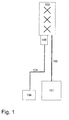
- a BTS/node B 101 is connected to an antenna 102 through a coaxial feeder cable 103.
- the control data for controlling the radiation direction of the antenna is created in a MCU (Master Control Unit) 104 and sent to an external control unit 106, such as a RET (Remote-Controlled Electrical Down-Tilt) unit, via an RS485 connection 105.
- MCU Master Control Unit
- RET Remote-Controlled Electrical Down-Tilt
- the remote control data signals are, usually inside a TMA, converted in a layer-1 converter, also called CILOC (Current Injector Layer One Converter), and a RS485 data connection is used between the CILOC and the antenna.
- the remote control data communication is thus sent partly over the coaxial antenna feeder cable and partly using a RS485 data connection.
- OOK modulation On Off Keying modulation
- OOK the presence or absence of carrier is used for representing the information, a logical 1 is modulated as "carrier off” and a logical 0 s modulated as "carrier on”.
- Fig. 2 schematically shows an exemplary control system for controlling the radiation direction of an antenna beam according to the second alternative of the AISG standard.
- the control system in fig. 2 includes a BTS/ Node B 201 connected to an antenna 202 via a coaxial feeder cable 203 carrying RF signals to the antenna.
- the control data for controlling the radiation direction of the antenna is created in a MCU 204 and sent to a converter 207 via an RS485 connection 205.
- the converter 207 receives the control data on the RS485 connection 205, modulates the data using OOK and superposes the OOK signals on the RF signals on the coaxial feeder cable 203.
- a CILOC (Current Injector Layer One Converter) 208 connected to the coaxial cable 203, receives the RF signals and the superposed control data on the cable.
- the CILOC 208 can be included in a TMA (Tower mounted amplifier).
- the CILOC 208 demodulates the control data and sends the control data to a RET unit (Remote-Controlled Electrical Down-Tilt) unit 206 via a second RS485 connection 209.
- RET unit Remote-Controlled Electrical Down-Tilt
- Fig. 3 shows the details of the CILOC and the RET unit according to the second alternative of the AISG standard.
- the CILOC 303 is connected to the coaxial feeder cable 301 and receives the RF signals and the superposed control data on the cable.
- the CILOC 303 includes a filter 304, detecting means 305 such as a detector, and an RS485 circuit 306.
- the filter 304 filters out the OOK modulated control.
- the detector 305 detects the OOK modulated control data and provides the control data to the RS485 circuit 306.
- the RS485 circuit 306 converts the control data into an RS485 signal being on the format suitable for an RS485 connection.
- the control data is then sent from the CILOC 303 to a RET unit 308 via an RS485 connection 307.
- the coaxial feeder cable 301 has one conductor and one screening wire.
- the control data signal on the coaxial cable 301 is further OOK modulated.
- the RS485 cable 307 has two conductors, one screening wire and one grounding wire.
- the control data signal received by the CILOC 303 thus has to be converted from OOK modulation and coaxial cable format into a format suitable for an RS485 connection. This is done by the RS485 circuit 306.
- the control data is provided via the RS485 connection 307 to the RET unit 308.
- the RET unit includes a second RS485 circuit 309 that converts the control data from the RS485 signalling format to logical signal, such as TTL signals (Transistor Transistor Logic signals), readable by control means 310, such as a CPU (Central Processing Unit).
- the RS485 circuit 309 provides the TTL signals to the CPU 310.
- the CPU 310 processes the control data and sends the control data to a motor control circuit 311.
- the motor control circuit 311 produces motor control signals for controlling a motor 312. Controlled by the motor control signals the motor 312 alters the radiation direction of the antenna by displacing a phase shifting means.
- the inventors have realised that the background art system shown in fig. 3 , working according to the AISG standard, can be simplified and be made more robust.
- An analysis of the background art system gives that the control signals are filtered out by filter 304 and detected by the detector 305 in the CILOC 303.
- the control signals are then first converted to a signal format suitable for an RS485 connection in an RS485 circuit 306, then provided to the RET unit 308 on an RS485 connection and then converted once more in an other RS485 circuit 309 into logical level signals readable by a CPU 310.
- the present invention aims to simplify the transfer of the control signals from the filter 304 to the CPU 310.
- FIG. 4 An exemplary embodiment of a control system according to the present invention is shown in fig. 4 .
- a number of parts of the system in fig. 4 are the same or similar to the ones shown in fig. 3 and are placed at the same location in the control system as in fig. 3 . These parts are the coaxial feeder cable 401, the antenna 402, the external control unit 405 (the RET unit), the control means 407 (the CPU), the Motor control circuit 408 and the motor 409.
- Some parts of the system have been changed or moved in the exemplary embodiment according to the invention. These parts are the CIN (Current Injector), the detecting means 406 and the jumper cable connection 404 between the CIN and the external control unit 405.
- the CIN is here just a filtering means 403, which is a much less complex circuit than the CILOC 303 in fig. 3 .
- the detecting means 406 is here moved from the CILOC in fig. 3 and is incorporated in the external control unit 405.
- the exemplary control system according to the invention does not use an RS485 connection for the control signals filtered out by the filtering means 403.
- the connection 404 is thus not an RS485 connection. There is therefore no need for the two RS485 circuits 306 and 309 shown in fig. 3 in a system according to the invention.
- the CIN here only includes filtering means 403 that filters out the OOK modulated control signals superposed on the feeder cable and directly provides these control signals on a jumper cable 404 to detecting means 406, such as a detector, which detects the OOK modulated control signals and provides the control signals to control means 407, preferably being a CPU, on a signal format readable by the control means 407.
- detecting means 406 such as a detector, which detects the OOK modulated control signals and provides the control signals to control means 407, preferably being a CPU, on a signal format readable by the control means 407.
- the CIN does here not include an RS485 circuit and the RET unit 405 does also not include an RS485 circuit as in the background art.
- Two RS485 circuits can thus be omitted by implementation of the invention.
- the invention thereby reduces the number of circuits and the complexity in the control system.
- the control system according to the invention has less electronic circuitry and is thereby both more robust (for example less sensitive to lightning strikes and the like) and is less costly to produce.
- the cable 404 is further a coaxial cable having one conductor and one screening wire compared to the RS485 cable 307 in fig. 3 having two conductors, one screening wire and one grounding wire. Fewer conductors in the cable of the inventive solution mean that fewer conductors have to be protected against environmental problems, such as lightning strikes and the like.
- the motor 409 and the motor control circuit 408 can be partly or totally incorporated within the casing of the antenna 402.
- the external control unit 405 includes the detecting means 406, the control means 407, the motor control circuit 408, and the motor 409.
- the filtering means 403 is situated outside the external control unit 405, close to the external control unit 405, or more far away.
- the motor control circuit 408 and the motor 409 are situated within the casing of the antenna 402.
- the detecting means 406 and the control means 407 are in this embodiment situated outside the casing of the antenna 402, in the external control unit 405 attached to the antenna.
- the motor control circuit 408, the motor 409 and the control means 407 are situated within the casing of the antenna 402.
- the control means 407 can in this embodiment be placed behind a cover in the antenna casing, thereby being possible to switch and upgrade.
- the detecting means 406 is in this embodiment situated outside the casing of the antenna, in the external control unit 405 attached to the antenna.
- the different embodiments of the placing of the motor 409, the motor control circuit 408, the control means 407 and the detecting means 406 have different advantages. It is generally advantageous, regarding robustness, to include as much as possible of the electronic circuitry within the antenna casing since this casing is constructed to be protected against environmental threats, such as lightning strikes and the like.
- the embodiments having a differing number of parts in the external control unit, outside the casing of the antenna have the positive feature that they could be implemented in existing systems, without altering the contents of the antenna of the existing system. Such embodiments could thus be used for upgrading existing systems according to the teachings of the present invention.
- the embodiments according to the invention, having electric circuitry situated in the external control unit outside the casing of the antenna, have nevertheless better environmental protection than background art systems since two RS485 circuits and the RS485 connection present in background art systems are omitted.
- Fig. 5 schematically shows the major components of an exemplary embodiment of the CIN of the present invention.
- the CIN is connectable to the feeder cable 501 that carries RF signals between BTS/ Node B and the antenna.
- the CIN includes a filtering means 502, including a capacitor 503 and an inductor 504, that filters out DC and control signals for the antenna from the RF signals on the feeder cable 501.
- the control signals on the feeder cable have a much lower frequency than the RF signals.
- the control signals can, for example be 2 MHz OOK signals. Also other frequencies and modulations can be used for the control signals.
- DC and control signals are provided to a jumper cable 505 that delivers the control signals to a detector in the external control unit.
- the CIN can be included in a TMA (Tower mounted amplifier) or be situated outside a TMA.
- Fig. 6 schematically shows the major components of an exemplary embodiment of the detecting means 602 of the present invention.
- the detecting means 602 receives OOK modulated signals on a jumper cable 601.
- the detecting means includes a level detecting circuit, including a diode 604 and a capacitor 603, which detects the control signals. These detected control signals are provided to a CPU connection 605 for delivery to the control means (CPU).
- the DC is used by the motor 409 in fig. 4 and other electrical circuitry in the antenna unit.
- figs. 5 and 6 show schematic views of the major parts of the CIN and detecting means.
- the detector could for instance also include transistor circuits and filters.
- the MCU 204 provides OOK modulated control data to the converting means 207 that superposes them on the RF signal on the feeder cable.
- RS485 is not used at all for controlling the radiation direction of the antenna, OOK signals are instead used all the way from the MCU to the RET unit. No RS485 converting circuits or RS485 cables are thus needed for this embodiment, which makes the control system both less complex and less costly.
- control data can be modulated using other modulation than OOK.
- FSK Frequency Shift Keying
- any other type of suitable modulation can be used for modulating the control data according to this embodiment.
- Different kinds of modulations have different characteristics regarding bitrate and robustness as is known by a skilled person.
- the type of modulation to be used is preferably chosen with respect to these characteristics.
- control system the base station, the communication system and the method for controlling according to the invention may be modified by those skilled in the art, as compared to the exemplary embodiments described above.
- a number of different components, circuits and cables can, for instance, be used for implementing a control system according to the invention.
- the different parts of a control system according to the invention can also be situated in different parts and casings of existing antenna systems.
- a first additional embodiment provides a control system for controlling radiation direction of an antenna beam of an antenna (402), the radiation direction being adjustable by an actuating device influencing phase shifting means based on an actuating signal
- the system including filtering means (403, 502) connected, in use, to a feeder cable (401, 501) arranged for carrying RF signals and a control signal, said filtering means (403, 502) being arranged for filtering out said control signal; and an external control unit (405), attached to said antenna (402), including detecting means (406, 602) and control means (407), said detecting means (406, 602) being arranged for detecting said filtered out control signal, said control means (407) being arranged for producing the actuating signal based on the detected control signal.
- the system is characterized in that said filtering means (403, 502) is directly connected to said external control unit (405) so as to provide the filtered out control signal directly to said external control unit (405).
- the detected control signal is in a signal format suitable for input in a logical circuit.
- said control means (407) is a processor.
- a converting means (207) is arranged for supplying control signals to the feeder cable (401, 501).
- said converting means (207) is arranged for modulating control signals and supplying the modulated control signals to the feeder cable (401, 501).
- control signals are modulated using OOK (On Off Keying).
- control signals are modulated using FSK (Frequency Shift Keying).
- said converting means (207) is arranged for superposing control signals on the RF signal on the feeder cable (401, 501).
- said filtering means (403, 502) includes a capacitor (503) and an inductance (504).
- said detecting means (406, 602) includes a diode (604) and a capacitor (603).
- said filtering means (403, 502) is located inside a TMA (Tower Mounted Amplifier).
- the external control unit (405) is a RET (Remote-Controlled Electrical Down-Tilt) unit.
- second control means (204) is arranged for providing control signals to said converting means (207).
- control signals is provided to said converting means (207) being in signal format RS485.
- control signals is provided to said converting means (207) being OOK modulated.
- a sixteenth additional embodiment provides a base station including a control system according to one of the first to fifteenth additional embodiment.
- a seventeenth additional embodiment provides a communication system including base stations including a control system according to one of the first to fifteenth additional embodiment.
- An eighteenth additional embodiment provides a method for controlling radiation direction of an antenna beam of an antenna (402), the radiation direction being adjustable by an actuating device influencing phase shifting means based on an actuating signal, the method including the steps of
Landscapes
- Engineering & Computer Science (AREA)
- Computer Networks & Wireless Communication (AREA)
- Signal Processing (AREA)
- Variable-Direction Aerials And Aerial Arrays (AREA)
- Radio Transmission System (AREA)
Applications Claiming Priority (2)
| Application Number | Priority Date | Filing Date | Title |
|---|---|---|---|
| SE0601909A SE530306C2 (sv) | 2006-09-15 | 2006-09-15 | Kommunikationslösning för antenner |
| EP07808808.5A EP2062330B1 (fr) | 2006-09-15 | 2007-09-12 | Solution de communication pour antennes |
Related Parent Applications (1)
| Application Number | Title | Priority Date | Filing Date |
|---|---|---|---|
| EP07808808.5A Division EP2062330B1 (fr) | 2006-09-15 | 2007-09-12 | Solution de communication pour antennes |
Publications (2)
| Publication Number | Publication Date |
|---|---|
| EP2999048A1 true EP2999048A1 (fr) | 2016-03-23 |
| EP2999048B1 EP2999048B1 (fr) | 2017-05-31 |
Family
ID=39184033
Family Applications (2)
| Application Number | Title | Priority Date | Filing Date |
|---|---|---|---|
| EP07808808.5A Active EP2062330B1 (fr) | 2006-09-15 | 2007-09-12 | Solution de communication pour antennes |
| EP15190593.2A Active EP2999048B1 (fr) | 2006-09-15 | 2007-09-12 | Solution de communication destinée à des antennes |
Family Applications Before (1)
| Application Number | Title | Priority Date | Filing Date |
|---|---|---|---|
| EP07808808.5A Active EP2062330B1 (fr) | 2006-09-15 | 2007-09-12 | Solution de communication pour antennes |
Country Status (4)
| Country | Link |
|---|---|
| US (1) | US8279127B2 (fr) |
| EP (2) | EP2062330B1 (fr) |
| SE (1) | SE530306C2 (fr) |
| WO (1) | WO2008033076A1 (fr) |
Families Citing this family (10)
| Publication number | Priority date | Publication date | Assignee | Title |
|---|---|---|---|---|
| JP2011524050A (ja) | 2008-06-12 | 2011-08-25 | マゼラン テクノロジー ピーティーワイ.エルティーディー. | アンテナ設計およびインテロゲータシステム |
| EP2340683B1 (fr) | 2008-10-30 | 2012-11-28 | Kathrein-Werke KG | Installation d'antenne à distance pour plusieurs stations de base se partageant une seule ligne d'alimentation hf pour la transmission des signaux de haute frequence, de commande et de surveillance ainsi que de la tension continue d'alimentation |
| KR101945405B1 (ko) | 2012-01-27 | 2019-02-08 | 주식회사 케이엠더블유 | 이동통신 기지국의 안테나 시스템 |
| KR20130130281A (ko) * | 2012-05-22 | 2013-12-02 | 엘에스전선 주식회사 | 안테나 위상 변환 장치 및 이를 이용하는 안테나 위상 변환 시스템 |
| WO2015163580A1 (fr) * | 2014-04-22 | 2015-10-29 | 주식회사 케이엠더블유 | Appareil de commande d'antenne de station de base pour communications mobiles |
| KR101635932B1 (ko) | 2014-04-22 | 2016-07-05 | 주식회사 케이엠더블유 | 이동통신 기지국 안테나 제어 장치 |
| DE102014011822A1 (de) * | 2014-08-08 | 2016-02-11 | Kathrein-Werke Kg | Antennenanlage für mehrere Primaries, insbesondere mehrere Basisstationen |
| WO2016052779A1 (fr) * | 2014-10-01 | 2016-04-07 | 주식회사 케이엠더블유 | Dispositif de commande d'antenne portable et système de commande d'antenne |
| US10044417B2 (en) | 2015-07-07 | 2018-08-07 | Huawei Technologies Co., Ltd. | Systems and methods for RRU control messaging architecture for massive MIMO systems |
| US11289799B2 (en) * | 2018-05-01 | 2022-03-29 | Commscope Technologies Llc | Base station antennas with compact remote electronic tilt actuators for controlling multiple phase shifters |
Citations (2)
| Publication number | Priority date | Publication date | Assignee | Title |
|---|---|---|---|---|
| US20050113047A1 (en) * | 2003-11-25 | 2005-05-26 | Duk-Yong Kim | Antenna remote control apparatus of mobile communication base station system |
| WO2006057613A1 (fr) | 2004-11-26 | 2006-06-01 | Powerwave Technologies Sweden Ab | Systeme de controle d'antenne |
Family Cites Families (6)
| Publication number | Priority date | Publication date | Assignee | Title |
|---|---|---|---|---|
| US6047199A (en) | 1997-08-15 | 2000-04-04 | Bellsouth Intellectual Property Corporation | Systems and methods for transmitting mobile radio signals |
| US6266545B1 (en) | 1998-10-21 | 2001-07-24 | Telefonaktiebolaget Lm Ericsson (Publ) | Transferring data in a fixed-site radio transceiver station by modulating power supply current |
| WO2002076115A2 (fr) * | 2001-03-19 | 2002-09-26 | Remec, Inc. | Multiplexeurs intelligents dans un systeme de gestion de ligne d'antenne |
| US6864837B2 (en) * | 2003-07-18 | 2005-03-08 | Ems Technologies, Inc. | Vertical electrical downtilt antenna |
| GB0425813D0 (en) * | 2004-11-24 | 2004-12-29 | Finglas Technologies Ltd | Remote control of antenna line device |
| SE528018C2 (sv) | 2004-11-26 | 2006-08-08 | Powerwave Technologies Sweden | Antennstyrsystem |
-
2006
- 2006-09-15 SE SE0601909A patent/SE530306C2/sv unknown
-
2007
- 2007-09-12 US US12/441,375 patent/US8279127B2/en active Active
- 2007-09-12 WO PCT/SE2007/000795 patent/WO2008033076A1/fr not_active Ceased
- 2007-09-12 EP EP07808808.5A patent/EP2062330B1/fr active Active
- 2007-09-12 EP EP15190593.2A patent/EP2999048B1/fr active Active
Patent Citations (2)
| Publication number | Priority date | Publication date | Assignee | Title |
|---|---|---|---|---|
| US20050113047A1 (en) * | 2003-11-25 | 2005-05-26 | Duk-Yong Kim | Antenna remote control apparatus of mobile communication base station system |
| WO2006057613A1 (fr) | 2004-11-26 | 2006-06-01 | Powerwave Technologies Sweden Ab | Systeme de controle d'antenne |
Non-Patent Citations (1)
| Title |
|---|
| THE AISG STANDARD, 30 July 2004 (2004-07-30) |
Also Published As
| Publication number | Publication date |
|---|---|
| SE0601909L (sv) | 2008-03-16 |
| EP2062330A4 (fr) | 2010-02-17 |
| WO2008033076A1 (fr) | 2008-03-20 |
| EP2999048B1 (fr) | 2017-05-31 |
| US8279127B2 (en) | 2012-10-02 |
| US20100164803A1 (en) | 2010-07-01 |
| SE530306C2 (sv) | 2008-04-29 |
| EP2062330B1 (fr) | 2015-10-21 |
| EP2062330A1 (fr) | 2009-05-27 |
Similar Documents
| Publication | Publication Date | Title |
|---|---|---|
| EP2999048B1 (fr) | Solution de communication destinée à des antennes | |
| EP1142347B1 (fr) | Procede et systeme combinant jack radio et systeme de radiocommunications hf | |
| US10886610B2 (en) | Portable antenna control device and antenna control system | |
| EP2808944A1 (fr) | Système d'antenne d'une station de base de communication mobile | |
| CN106952480A (zh) | 一种车辆检测器及车辆检测器的控制方法 | |
| CN101197468B (zh) | 一种天线和一种基站系统 | |
| KR100921236B1 (ko) | 데이터 전송 시스템 및 전송 방법 | |
| EP3190718A1 (fr) | Appareil, dispositif, et procédé d'extension de fonction d'antenne | |
| US7113668B2 (en) | System for the transmission of signals to or between underwater installations | |
| CN202748849U (zh) | 路侧单元设备 | |
| CN103840252A (zh) | 天线装置和用于形成天线装置的方法 | |
| CN203909995U (zh) | 一种海况信息采集发射模块 | |
| CN218570226U (zh) | 射频识别器及车辆识别装置 | |
| EP2436115B1 (fr) | Commande sur câbles coaxiaux pour dispositifs de réception de signal de télévision | |
| CN109895957B (zh) | 一种集成式多功能e航标设备 | |
| US11199645B2 (en) | Locate or tracer wire grounding terminal | |
| KR102057968B1 (ko) | 휴대용 안테나 제어 장치 및 안테나 제어 시스템 | |
| KR101572251B1 (ko) | 잠수함 | |
| JP7064861B2 (ja) | 無線通信装置 | |
| CN120879189A (zh) | 用于水表的改进型远程物联网天线解决方案 | |
| CN104270213A (zh) | 一种基于rds的无线应急预警广播设备的激励器 | |
| EP3719304A1 (fr) | Système de communication pour éolienne | |
| CN105590073A (zh) | 射频识别系统阅读器 | |
| Tonn | Modular VLF/LF and HF Buoyant cable Antenna and Method | |
| EP3057379A1 (fr) | Unité de commande, système et procédé permettant d'envoyer et de recevoir des signaux radio dans plusieurs plages de fréquences |
Legal Events
| Date | Code | Title | Description |
|---|---|---|---|
| PUAI | Public reference made under article 153(3) epc to a published international application that has entered the european phase |
Free format text: ORIGINAL CODE: 0009012 |
|
| AC | Divisional application: reference to earlier application |
Ref document number: 2062330 Country of ref document: EP Kind code of ref document: P |
|
| AK | Designated contracting states |
Kind code of ref document: A1 Designated state(s): AT BE BG CH CY CZ DE DK EE ES FI FR GB GR HU IE IS IT LI LT LU LV MC MT NL PL PT RO SE SI SK TR |
|
| 17P | Request for examination filed |
Effective date: 20160531 |
|
| RBV | Designated contracting states (corrected) |
Designated state(s): AT BE BG CH CY CZ DE DK EE ES FI FR GB GR HU IE IS IT LI LT LU LV MC MT NL PL PT RO SE SI SK TR |
|
| GRAP | Despatch of communication of intention to grant a patent |
Free format text: ORIGINAL CODE: EPIDOSNIGR1 |
|
| INTG | Intention to grant announced |
Effective date: 20161130 |
|
| GRAJ | Information related to disapproval of communication of intention to grant by the applicant or resumption of examination proceedings by the epo deleted |
Free format text: ORIGINAL CODE: EPIDOSDIGR1 |
|
| INTC | Intention to grant announced (deleted) | ||
| GRAR | Information related to intention to grant a patent recorded |
Free format text: ORIGINAL CODE: EPIDOSNIGR71 |
|
| GRAS | Grant fee paid |
Free format text: ORIGINAL CODE: EPIDOSNIGR3 |
|
| GRAA | (expected) grant |
Free format text: ORIGINAL CODE: 0009210 |
|
| AC | Divisional application: reference to earlier application |
Ref document number: 2062330 Country of ref document: EP Kind code of ref document: P |
|
| AK | Designated contracting states |
Kind code of ref document: B1 Designated state(s): AT BE BG CH CY CZ DE DK EE ES FI FR GB GR HU IE IS IT LI LT LU LV MC MT NL PL PT RO SE SI SK TR |
|
| INTG | Intention to grant announced |
Effective date: 20170425 |
|
| REG | Reference to a national code |
Ref country code: CH Ref legal event code: EP Ref country code: GB Ref legal event code: FG4D |
|
| REG | Reference to a national code |
Ref country code: AT Ref legal event code: REF Ref document number: 898212 Country of ref document: AT Kind code of ref document: T Effective date: 20170615 |
|
| REG | Reference to a national code |
Ref country code: IE Ref legal event code: FG4D |
|
| REG | Reference to a national code |
Ref country code: DE Ref legal event code: R096 Ref document number: 602007051217 Country of ref document: DE |
|
| REG | Reference to a national code |
Ref country code: FR Ref legal event code: PLFP Year of fee payment: 11 |
|
| REG | Reference to a national code |
Ref country code: NL Ref legal event code: MP Effective date: 20170531 |
|
| REG | Reference to a national code |
Ref country code: LT Ref legal event code: MG4D |
|
| REG | Reference to a national code |
Ref country code: AT Ref legal event code: MK05 Ref document number: 898212 Country of ref document: AT Kind code of ref document: T Effective date: 20170531 |
|
| PG25 | Lapsed in a contracting state [announced via postgrant information from national office to epo] |
Ref country code: AT Free format text: LAPSE BECAUSE OF FAILURE TO SUBMIT A TRANSLATION OF THE DESCRIPTION OR TO PAY THE FEE WITHIN THE PRESCRIBED TIME-LIMIT Effective date: 20170531 Ref country code: LT Free format text: LAPSE BECAUSE OF FAILURE TO SUBMIT A TRANSLATION OF THE DESCRIPTION OR TO PAY THE FEE WITHIN THE PRESCRIBED TIME-LIMIT Effective date: 20170531 Ref country code: ES Free format text: LAPSE BECAUSE OF FAILURE TO SUBMIT A TRANSLATION OF THE DESCRIPTION OR TO PAY THE FEE WITHIN THE PRESCRIBED TIME-LIMIT Effective date: 20170531 Ref country code: FI Free format text: LAPSE BECAUSE OF FAILURE TO SUBMIT A TRANSLATION OF THE DESCRIPTION OR TO PAY THE FEE WITHIN THE PRESCRIBED TIME-LIMIT Effective date: 20170531 Ref country code: GR Free format text: LAPSE BECAUSE OF FAILURE TO SUBMIT A TRANSLATION OF THE DESCRIPTION OR TO PAY THE FEE WITHIN THE PRESCRIBED TIME-LIMIT Effective date: 20170901 |
|
| PG25 | Lapsed in a contracting state [announced via postgrant information from national office to epo] |
Ref country code: IS Free format text: LAPSE BECAUSE OF FAILURE TO SUBMIT A TRANSLATION OF THE DESCRIPTION OR TO PAY THE FEE WITHIN THE PRESCRIBED TIME-LIMIT Effective date: 20170930 Ref country code: SE Free format text: LAPSE BECAUSE OF FAILURE TO SUBMIT A TRANSLATION OF THE DESCRIPTION OR TO PAY THE FEE WITHIN THE PRESCRIBED TIME-LIMIT Effective date: 20170531 Ref country code: LV Free format text: LAPSE BECAUSE OF FAILURE TO SUBMIT A TRANSLATION OF THE DESCRIPTION OR TO PAY THE FEE WITHIN THE PRESCRIBED TIME-LIMIT Effective date: 20170531 Ref country code: BG Free format text: LAPSE BECAUSE OF FAILURE TO SUBMIT A TRANSLATION OF THE DESCRIPTION OR TO PAY THE FEE WITHIN THE PRESCRIBED TIME-LIMIT Effective date: 20170831 Ref country code: NL Free format text: LAPSE BECAUSE OF FAILURE TO SUBMIT A TRANSLATION OF THE DESCRIPTION OR TO PAY THE FEE WITHIN THE PRESCRIBED TIME-LIMIT Effective date: 20170531 |
|
| PG25 | Lapsed in a contracting state [announced via postgrant information from national office to epo] |
Ref country code: CZ Free format text: LAPSE BECAUSE OF FAILURE TO SUBMIT A TRANSLATION OF THE DESCRIPTION OR TO PAY THE FEE WITHIN THE PRESCRIBED TIME-LIMIT Effective date: 20170531 Ref country code: RO Free format text: LAPSE BECAUSE OF FAILURE TO SUBMIT A TRANSLATION OF THE DESCRIPTION OR TO PAY THE FEE WITHIN THE PRESCRIBED TIME-LIMIT Effective date: 20170531 Ref country code: DK Free format text: LAPSE BECAUSE OF FAILURE TO SUBMIT A TRANSLATION OF THE DESCRIPTION OR TO PAY THE FEE WITHIN THE PRESCRIBED TIME-LIMIT Effective date: 20170531 Ref country code: SK Free format text: LAPSE BECAUSE OF FAILURE TO SUBMIT A TRANSLATION OF THE DESCRIPTION OR TO PAY THE FEE WITHIN THE PRESCRIBED TIME-LIMIT Effective date: 20170531 Ref country code: EE Free format text: LAPSE BECAUSE OF FAILURE TO SUBMIT A TRANSLATION OF THE DESCRIPTION OR TO PAY THE FEE WITHIN THE PRESCRIBED TIME-LIMIT Effective date: 20170531 |
|
| PG25 | Lapsed in a contracting state [announced via postgrant information from national office to epo] |
Ref country code: PL Free format text: LAPSE BECAUSE OF FAILURE TO SUBMIT A TRANSLATION OF THE DESCRIPTION OR TO PAY THE FEE WITHIN THE PRESCRIBED TIME-LIMIT Effective date: 20170531 Ref country code: IT Free format text: LAPSE BECAUSE OF FAILURE TO SUBMIT A TRANSLATION OF THE DESCRIPTION OR TO PAY THE FEE WITHIN THE PRESCRIBED TIME-LIMIT Effective date: 20170531 |
|
| REG | Reference to a national code |
Ref country code: DE Ref legal event code: R097 Ref document number: 602007051217 Country of ref document: DE |
|
| PLBE | No opposition filed within time limit |
Free format text: ORIGINAL CODE: 0009261 |
|
| STAA | Information on the status of an ep patent application or granted ep patent |
Free format text: STATUS: NO OPPOSITION FILED WITHIN TIME LIMIT |
|
| REG | Reference to a national code |
Ref country code: CH Ref legal event code: PL |
|
| 26N | No opposition filed |
Effective date: 20180301 |
|
| PG25 | Lapsed in a contracting state [announced via postgrant information from national office to epo] |
Ref country code: SI Free format text: LAPSE BECAUSE OF FAILURE TO SUBMIT A TRANSLATION OF THE DESCRIPTION OR TO PAY THE FEE WITHIN THE PRESCRIBED TIME-LIMIT Effective date: 20170531 Ref country code: MC Free format text: LAPSE BECAUSE OF FAILURE TO SUBMIT A TRANSLATION OF THE DESCRIPTION OR TO PAY THE FEE WITHIN THE PRESCRIBED TIME-LIMIT Effective date: 20170531 |
|
| REG | Reference to a national code |
Ref country code: IE Ref legal event code: MM4A |
|
| REG | Reference to a national code |
Ref country code: BE Ref legal event code: MM Effective date: 20170930 |
|
| PG25 | Lapsed in a contracting state [announced via postgrant information from national office to epo] |
Ref country code: LU Free format text: LAPSE BECAUSE OF NON-PAYMENT OF DUE FEES Effective date: 20170912 |
|
| PG25 | Lapsed in a contracting state [announced via postgrant information from national office to epo] |
Ref country code: CH Free format text: LAPSE BECAUSE OF NON-PAYMENT OF DUE FEES Effective date: 20170930 Ref country code: IE Free format text: LAPSE BECAUSE OF NON-PAYMENT OF DUE FEES Effective date: 20170912 Ref country code: LI Free format text: LAPSE BECAUSE OF NON-PAYMENT OF DUE FEES Effective date: 20170930 |
|
| REG | Reference to a national code |
Ref country code: FR Ref legal event code: PLFP Year of fee payment: 12 |
|
| PG25 | Lapsed in a contracting state [announced via postgrant information from national office to epo] |
Ref country code: BE Free format text: LAPSE BECAUSE OF NON-PAYMENT OF DUE FEES Effective date: 20170930 |
|
| PG25 | Lapsed in a contracting state [announced via postgrant information from national office to epo] |
Ref country code: MT Free format text: LAPSE BECAUSE OF NON-PAYMENT OF DUE FEES Effective date: 20170912 |
|
| PG25 | Lapsed in a contracting state [announced via postgrant information from national office to epo] |
Ref country code: HU Free format text: LAPSE BECAUSE OF FAILURE TO SUBMIT A TRANSLATION OF THE DESCRIPTION OR TO PAY THE FEE WITHIN THE PRESCRIBED TIME-LIMIT; INVALID AB INITIO Effective date: 20070912 |
|
| PG25 | Lapsed in a contracting state [announced via postgrant information from national office to epo] |
Ref country code: CY Free format text: LAPSE BECAUSE OF FAILURE TO SUBMIT A TRANSLATION OF THE DESCRIPTION OR TO PAY THE FEE WITHIN THE PRESCRIBED TIME-LIMIT Effective date: 20170531 |
|
| PG25 | Lapsed in a contracting state [announced via postgrant information from national office to epo] |
Ref country code: TR Free format text: LAPSE BECAUSE OF FAILURE TO SUBMIT A TRANSLATION OF THE DESCRIPTION OR TO PAY THE FEE WITHIN THE PRESCRIBED TIME-LIMIT Effective date: 20170531 |
|
| PG25 | Lapsed in a contracting state [announced via postgrant information from national office to epo] |
Ref country code: PT Free format text: LAPSE BECAUSE OF FAILURE TO SUBMIT A TRANSLATION OF THE DESCRIPTION OR TO PAY THE FEE WITHIN THE PRESCRIBED TIME-LIMIT Effective date: 20170531 |
|
| P01 | Opt-out of the competence of the unified patent court (upc) registered |
Effective date: 20230518 |
|
| PGFP | Annual fee paid to national office [announced via postgrant information from national office to epo] |
Ref country code: DE Payment date: 20240820 Year of fee payment: 18 |
|
| PGFP | Annual fee paid to national office [announced via postgrant information from national office to epo] |
Ref country code: GB Payment date: 20240822 Year of fee payment: 18 |
|
| PGFP | Annual fee paid to national office [announced via postgrant information from national office to epo] |
Ref country code: FR Payment date: 20240821 Year of fee payment: 18 |