EP2999084B1 - Elektrische verbindungsvorrichtung für stromquellen-umschalter, und stromquellen-umschalter, der eine solche vorrichtung umfasst - Google Patents
Elektrische verbindungsvorrichtung für stromquellen-umschalter, und stromquellen-umschalter, der eine solche vorrichtung umfasst Download PDFInfo
- Publication number
- EP2999084B1 EP2999084B1 EP15185775.2A EP15185775A EP2999084B1 EP 2999084 B1 EP2999084 B1 EP 2999084B1 EP 15185775 A EP15185775 A EP 15185775A EP 2999084 B1 EP2999084 B1 EP 2999084B1
- Authority
- EP
- European Patent Office
- Prior art keywords
- connector
- controller
- power supply
- switching devices
- source
- Prior art date
- Legal status (The legal status is an assumption and is not a legal conclusion. Google has not performed a legal analysis and makes no representation as to the accuracy of the status listed.)
- Active
Links
Images



Classifications
-
- H—ELECTRICITY
- H02—GENERATION; CONVERSION OR DISTRIBUTION OF ELECTRIC POWER
- H02J—ELECTRIC POWER NETWORKS; CIRCUIT ARRANGEMENTS OR SYSTEMS FOR SUPPLYING OR DISTRIBUTING ELECTRIC POWER; SYSTEMS FOR STORING ELECTRIC ENERGY
- H02J9/00—Circuit arrangements for emergency or stand-by power supply, e.g. for emergency lighting
- H02J9/04—Circuit arrangements for emergency or stand-by power supply, e.g. for emergency lighting in which the distribution system is disconnected from the normal source and connected to a standby source
- H02J9/06—Circuit arrangements for emergency or stand-by power supply, e.g. for emergency lighting in which the distribution system is disconnected from the normal source and connected to a standby source with automatic change-over, e.g. UPS systems
- H02J9/061—Circuit arrangements for emergency or stand-by power supply, e.g. for emergency lighting in which the distribution system is disconnected from the normal source and connected to a standby source with automatic change-over, e.g. UPS systems for DC powered loads
-
- H—ELECTRICITY
- H02—GENERATION; CONVERSION OR DISTRIBUTION OF ELECTRIC POWER
- H02J—ELECTRIC POWER NETWORKS; CIRCUIT ARRANGEMENTS OR SYSTEMS FOR SUPPLYING OR DISTRIBUTING ELECTRIC POWER; SYSTEMS FOR STORING ELECTRIC ENERGY
- H02J9/00—Circuit arrangements for emergency or stand-by power supply, e.g. for emergency lighting
- H02J9/04—Circuit arrangements for emergency or stand-by power supply, e.g. for emergency lighting in which the distribution system is disconnected from the normal source and connected to a standby source
- H02J9/06—Circuit arrangements for emergency or stand-by power supply, e.g. for emergency lighting in which the distribution system is disconnected from the normal source and connected to a standby source with automatic change-over, e.g. UPS systems
- H02J9/068—Electronic means for switching from one power supply to another power supply, e.g. to avoid parallel connection
Definitions
- the present invention as defined in independent claim 1 relates to an interconnection device for improving the reliability of operation and facilitating, in a source inverter, the interconnection of the various constituents of the source inversion function, and a source inverter comprising this interconnection device. It finds an application in particular to the electrical power distribution networks in which it is necessary to be able to switch from one power source to another, in case of failure of one of the sources, for example in hospitals .
- such a network is provided with a source inverter device for switching, usually automatically, to an AC or backup power source when the main power source fails.
- the number of control and status feedback signals received by the controller greatly increases depending on the type of switching device.
- a switch-type switching apparatus requires a control signal, and a control status feedback signal.
- a bistable switching device such as a motorized switch, requires two control signals (open, close), a control status feedback signal (open / close).
- a bistable device with spring mechanism requires two control signals (opening, closing), two control status feedback signals (open / closed, loaded spring).
- this device is a protection device (circuit breaker for example)
- an additional electrical fault status feedback is required.
- a small protective device must be added to the voltage measurement cables and the status of this device must be known by an additional return signal.
- a withdrawable bistable device with a spring mechanism requires two control signals (opening, closing), four status feedback signals (open / closed, electrical fault, loaded spring, plugged in) and a signal the condition of the protection device of the voltage measurement as explained above.
- auxiliary voltages low voltage to control the switching devices (for example 230VAC or 400VAC) and very low voltage for control and monitoring signals (eg 24VDC).
- controllers are marketed, the number of inputs / outputs is insufficient for source inverters based withdrawable open circuit breakers.
- controllers with sufficient input / output numbers most are not easy to implement with circuit breakers, let alone with withdrawable open circuit breakers, without detailed explanations. This can lead to installation errors, including the forgetting of some of the other elements necessary to achieve a complete and safe source inverter function.
- the risks associated with the incorrect installation of the inverter device are the power cuts due to a bad wiring of the controller, the breakage of a generator due to an unsynchronized coupling, a hidden failure rendering the controller inoperative the day when one really needs it, with in some cases a very significant loss of money, even accidents on people who can go to the death.
- the plaintiff is aware of at least one incident per year, such as a source failover that is incompletely executed in a power supply network of a hospital in Europe, which puts the lives of certain patients at stake each time.
- At least one case known to the Applicant among these incidents was related to a bad wiring by the installer of the source reversal device.
- Devices complementary to the switching devices and the controller are generally of significant size, which is a problem when installing in an electrical panel in which the space is greatly reduced. They usually require wiring in which some unprotected cables connected to the inputs auxiliary protections are too long, contrary to the rules of the art, and presenting risks for property and people.
- the object of the invention is in particular to propose a device facilitating the implementation of a source inverter comprising a controller and two switching devices such as circuit breakers, possibly open, high power and withdrawable, with a level of high reliability in the implementation, so a high level of safety of operation.
- the subject of the invention is an interconnection device intended to secure and facilitate, in a source inverter device, the connection of a controller and at least two switching devices capable of ensuring switching to two power sources respectively.
- the interconnection device comprises a support, such as a plate, on which are mounted at least two source connectors and at least one control connector intended to respectively allow the connection of two switching devices and a controller to the device.
- interconnection and the support comprises a pre-wiring of the source and control connectors so as to allow, when a controller and two switching devices are connected to the interconnection device respectively by the control and source connectors, control by said controller of switching to one or the other of two power sources via either of the two switching devices.
- the subject of the invention is also, according to a second aspect, a source inverter device comprising a controller and at least two switching devices designed to switch to two power supply sources respectively, the controller being able to control the switchover from one source to the other by controlling the two switching devices.
- the source inverter device comprises an interconnection device as presented above, on which the controller and the two switching devices are connected respectively by the control and source connectors, so as to enable control by said controller of the switching to one or the other of two power sources via either of the two switching devices.
- the subject of the invention is also an electrical energy distribution network originating from one or the other of two power supply sources, this network comprising a source inverter device such as presented above, so as to allow switching from one to the other of the two power sources to supply said network.
- the interconnection device of the invention makes it possible, by fixing the wiring possibilities, taking into account all the signals necessary for safety, and by making the necessary connections, to eliminate the errors of installation and to increase the reliability of operation of a source inverter device.
- the interconnection device can be qualified in the laboratory and tested in production, to guarantee the installer its proper functioning, without the need to carry out a thorough inspection during the installation, thus saving installation time and time. important implementation.
- the interconnection device with its central plate, and with the associated cables, replaces more than 150 connection points necessary for the usual implementation.
- the device according to the invention allows a reduced implementation to only about an hour, without risk of hidden error.
- the device of the invention does not leave any possibility to an installer to make a mistake or to modify to dangerously simplify the installation, and ensures the proper functioning of a critical part of an architecture of distribution of electrical energy.
- the interconnection device makes it possible to optimize the cable lengths in all possible configurations of electrical installation boards: switching devices near or far from the controller, switching devices close to or distant from each other.
- the interconnection device remote from the controller, does not weigh down this table and reduces the wiring at the door hinge table.
- the interconnection device does not require positioning a bulky object near the switching devices and the busbars that connect them.
- FIG. 1 is schematically represented an example of a source inverter device according to the invention, intended to be installed in an electrical power distribution network having at least two alternative sources, permanent or not, power supply, to ensure the switchover from one to the other of the two sources of power for the supply of the electrical network.
- This source reversing device comprises a controller 2 and two switching devices 3, 4, for example of the circuit-breaker type 3, 4.
- the source inverter device comprises an interconnection device 1 provided with a certain number of connectors, some of which are referenced by the references 5, 6, 9 and 28, and which will be described in more detail below with reference to the figure 2 .
- This source inverter device also comprises two switching devices 3, 4, for example of circuit breaker type, which are intended to provide switching of the two power sources not shown.
- each switching device 3, 4 comprises a main circuit breaker device 7, 11 and an auxiliary protection device 8, 12 for the measurement of the upstream supply sources of 7, 11.
- the source inverter device comprises a controller 2, which is able to control the switching from one source to the other by controlling the two switching devices 3, 4.
- the inverter device also comprises a safety extra low voltage auxiliary supply device 13, implementing a battery 14 connected by a cable 19.
- This secure electrical auxiliary supply device 13 makes it possible to power the controller 2 electrically via the cables 18 and then 15.
- the interconnection device 1 also incorporates a switching system for electrically supplying the control coils and the spring charging motor of the switching devices 3, 4, called actuators of the switching devices 3, 4, so that these actuators are powered as soon as at least one power source is present.
- All these switching devices 3, 4 and auxiliary power supply 13, as well as the controller 2 are connected to the interconnection device 1, via the respective appropriate connectors 5, 6, 28, 9 on the device. interconnection 1, and cables, or plies of cables, respectively 16, 17, 18, and 15, connecting these devices 3, 4, 13, 2 to the connectors 5, 6, 28, 9 corresponding.
- the interconnection device 1 comprises a support 10, such as a plate 10, on which are mounted different connectors, including connectors 5, 6, 28, 9 presented above, which are otherwise pre-wired for the purpose to ensure, once connected to the corresponding devices, certain functions.
- two source connectors 5, 6 and a control connector 9 are mounted on the support 10, respectively allowing the connection of the two switching devices 3, 4 and the controller 2 to the interconnection device 1.
- the support comprises a pre-wiring of the source connectors 5, 6 and control 9, not visible on the Figures 1 and 2 .
- This pre-wiring is performed so as to enable control by the controller 2, connected via the control connector 9, to switch to one or the other of two power supply sources via the one or the other of the two switching devices 3, 4, respectively connected via the source connectors 5, 6.
- the support comprises a pre-wiring of the source connectors 5, 6 and control 9, not visible on the Figures 1 and 2 .
- This pre-wiring is made in such a way as to allow detection by the controller 2 of the good racking-in of the connectors 5, 6 and 9, respectively to the cables or cable layers 16, 17, 15, by means of at least one current loop. which passes through the corresponding connectors and is monitored by the controller 2.
- Pre-wiring of the auxiliary power connector 28, not visible on the Figures 1 and 2 can also be provided for the same purpose. This pre-wiring is thus performed so as to allow detection by the controller 2 proper plugging of the auxiliary power connector 28 to the cable or the cable ply 18, by means of at least the current loop that passes by this auxiliary power connector 28, monitored by the controller 2.
- FIG. 2 there is provided a series of voltage selection connectors 27 mounted on the support 10, to enable the control circuits of the switching devices 3, 4 to be powered on several voltage levels and in several configurations.
- the support 10 then comprises a pre-wiring, not visible in the figures, of one of these voltage selection connectors 27, of one of the source connectors 5, 6.
- the support 10 also comprises auxiliary relays and a pre-wiring between the source connectors 5, 6 and the control connector 9, to allow the adaptation of the voltage of one or more of the state signals (low voltage). of the switching device 3, 4 corresponding to a voltage value adapted for an input signal of the controller 2 (very low voltage).
- the support 10 may also include auxiliary relays and pre-wiring between the source connectors 5, 6 and the control connector 9, to allow the adaptation of the voltage of one or more of the control signals (very low voltage ) of the controller 2 corresponding to a voltage value adapted for an input signal (low voltage) of the switching device 3, 4.
- a signal from or to one of the switching devices 3, 4 can be converted (adapted) into a signal adapted to the controller 2. This avoids having to connect additional relays to the source reversal device 5 , and thus reduces the time of implementation and the risks of errors and hidden failures.
- the support 10 comprises pre-wiring, not visible in the figures, of the control connector 9 and the two source connectors 5, 6, to allow the interlocking of the two switching devices 3, 4 This safety function prohibits the closing of one of the two switching devices 3, 4 when the other is already closed, and prohibits the coupling of the two power sources respectively connected to the two switching devices 3, 4.
- This electrical interlock acts on the opening coils of the switching devices 3, 4. It effectively makes it impossible to close one of the switching devices 3, 4, for example by the buttons on the front face of the switchgear. switching (respectively 3, 4), if the other is already closed (respectively 4, 3). It therefore also makes it impossible to create an unsynchronized coupling between the two power supply sources respectively connected to the two switching devices 3, 4.
- this interlocking makes it impossible to connect a generator, and thus prevents the risk of mechanical failure.
- This interlocking is permanently activated and in the absence of energy on the controller 2 to increase the operating reliability of the source inverter.
- This temporary deactivation allows a closed transition (in some cases also called fugitive coupling transition) while preserving the safety of operators and facilities outside these often brief and time-spaced transition phases.
- interlocking In this case the risks of dangerous manual operation are not or only partially prevented.
- interlocking With this variant of the invention, interlocking remains present and ensures its protection function. Simply activate the relay in question to temporarily disable this interlocking.
- the inter-locking is activated (the state of inter-locking is represented by INTER_ON) as soon as one or the other source is present, therefore in all phases except phase B.
- the activation of the signal INTER_OFF (phase E) has the effect of disabling interlocking the transition time.
- the signal INTER_OFF is itself deactivated as soon as the transition is completed which reactivates interlock INTER_ON (phase F) and again prevents any risk of simultaneous closing of the main switching devices.
- one or more auxiliary supply connectors 28, at least one of which allows the connection, to the interconnection device 1, of an auxiliary supply device 13, to be connected to the support 10, can be provided. secure preference and putting for example a battery 14.
- the support then comprises a pre-wiring, not visible in the figures, of the auxiliary power supply connector 28 in question and the control connector 9, to allow the power supply of the controller 2.
- the support also comprises pre-wiring, not visible in the figures, of the auxiliary power supply connector 28 in question and the control connector 9, for the transmission to the controller of the state information of the secure power supply device 13 as for example. example a fault signal of charge of the battery.
- a low-voltage auxiliary power supply is used for the control coils and the spring charging motor of the switching devices called actuators of the switching devices (for example 230VAC or 400VAC).
- a very low voltage auxiliary power supply is used for the control and monitoring signals (for example 24VDC).
- the power supply 13 of the electronic controller 2 must be secured and use a battery 14. And the supply of the actuators of the switching devices 3, 4 must be present as soon as the one of the two power sources is present.
- the support 10 can integrate the specific device for auxiliary supply of the actuators of the switching devices 3, 4.
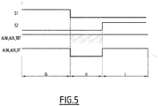
- This embodiment makes it possible to obtain a graph of the signals relating to the sources S1, S2, the low voltage auxiliary power supply (ALIM_AUX_BT) and the auxiliary power supply very low voltage (ALIM_AUX_TBT) as represented on the figure 5 .
- the low voltage auxiliary power supply (ALIM_AUX_BT) is present as soon as one of the two sources S1, S2 is available either during phases G and I, and the auxiliary power supply 13 very low voltage (ALIM_AUX_TBT) is present permanently thanks to securing by means of the battery 14 in phase H.
- the invention can implement, on the support 10, an auxiliary inverter device, detailed on the figure 6 , connected to the interconnection device of the figure 2 and comprising at least one auxiliary switching element 24 and at least one control relay 25.
- this auxiliary inverter device supplies the necessary energy (ALIM_ACTUATEURS) to the actuators of the switching devices 3, 4 and / or to the secure power supply 13.
- This auxiliary inverter device ensures the connection to the source S1 or S2 present, as soon as one of these two sources S1, S2 is available, in the absence of any intervention of the controller 2, thanks to the auxiliary switching element 24 , and at the same time allows the controller 2, if necessary, to choose the source S1, S2 to be used when both are present through the control relay (s) 25.
- This auxiliary inverter device guarantees the non-coupling of the two sources S1, S2 by mechanical interlocking integrated into the auxiliary switching element 24.
- Such a controlled auxiliary inverter device thus allows the controller 2 to deactivate a source S1, S2 if it falls below the operating threshold of the actuators, without preventing the inverter device from freely connecting to the first source S1, S2 present in the absence of controller 2 by supplying the control circuits of the switching device 3, 4 corresponding.
- auxiliary inverter devices allow one or the other of the possibilities, but not the combination of the two without the addition of an electronic device specific to the management of this auxiliary inverter which can present its own modes of failure and thus weaken the robustness of the device especially vis-à-vis the free connection to the first source present, described above.
- the interconnection device 1 of the invention can also be adapted to actuators of the switching devices 3 and 4 whose operating voltages are variable and different through the connectors 27 and jumpers E, F.
- the source inverter device can be three-pole (3 phases), or four-pole (three phases L1, L2, L3 and a neutral N).
- the actuators of the switching devices 3 and 4 may be chosen to operate with a voltage of 230VAC or 400VAC, either a phase-to-neutral voltage or a phase-to-phase voltage.
- the auxiliary inverter device described in figure 6 therefore works even in the absence of neutral but allows to switch two phases L1, L2 and the possible neutral N.
- the interconnection device 1 of the invention can also integrate voltage matching relays to simplify the interface between the electronic controller 2 and the switching devices 3, 4.
- the interconnection device 1 can comprise electromechanical relays which will allow the controller 2, all or some of the output signals to be very low voltage signals (for example 24VDC) to activate actuators operating at low voltage (for example 230VAC or 400VAC).
- the interconnection device 1 may also include electromechanical relays which will enable the controller 2, all or some of the input signals to be very low voltage signals (for example 24VDC) to come to interface with sensors delivering a signal in low voltage (for example 230VAC or 400VAC).
- a pre-wiring of the voltage adaptation relay or relays can also be provided, in order to allow the detection by the controller 2 of the good racking of the connectors 5, 6 and 9 respectively to the cables or cable plies 16, 17 , 15, by means of at least one current loop which passes through the corresponding connectors and which is monitored by the controller 2.
- the interconnection device 1 can be used with or without implementation of the options described, simply by using the connectors concerned with the corresponding cables or cable plies.
- the installer does not use conventional wiring for less common installation variants, and is therefore assured of good productivity and a reliable and secure result, without error or hidden failure. .
Landscapes
- Business, Economics & Management (AREA)
- Emergency Management (AREA)
- Engineering & Computer Science (AREA)
- Power Engineering (AREA)
- Inverter Devices (AREA)
- Remote Monitoring And Control Of Power-Distribution Networks (AREA)
Claims (12)
- Verbindungseinrichtung (1), die dazu dient, in einer Stromquellenumschaltvorrichtung die Verbindung einer Steuervorrichtung (2) und mindestens zweier Schaltgeräte (3, 4), die geeignet sind, das Schalten auf jeweils zwei elektrische Versorgungsquellen sicherzustellen, zu schützen und zu vereinfachen, umfassend einen Träger (10), wie eine Platine (10), auf dem mindestens zwei Stromquellenanschlüsse (5, 6) und mindestens ein Steueranschluss (9) montiert sind, die vorgesehen sind, jeweils die Verbindung von zwei Schaltgeräten (3, 4) und einer Steuervorrichtung (2) mit der Verbindungseinrichtung (1) zu ermöglichen, und der Träger (10) eine Vorverkabelung der Stromquellenanschlüsse (5, 6) und des Steueranschlusses (9) derart umfasst, dass, wenn eine Steuervorrichtung (2) und zwei Schaltgeräte (3, 4) mit der Verbindungseinrichtung jeweils über den Steueranschluss (9) und die Stromquellenanschlüsse (5, 6) verbunden sind, die Steuerung des Umschaltens zwischen der einen und der anderen der zwei elektrischen Versorgungsquellen über das eine oder das andere der zwei Schaltgeräte (3, 4) ermöglicht wird, dadurch gekennzeichnet, dass die Verbindungseinrichtung mindestens eine Hilfsumschaltvorrichtung (24, 25) umfasst, die auf dem Träger (10) montiert ist und mindestens ein Hilfsschaltelement (24) und mindestens ein Steuerrelais (25) aufweist, und dass der Träger (10) eine Vorverkabelung dieser Hilfsumschaltvorrichtung (24, 25), des Steueranschlusses (9) und der zwei Stromquellenanschlüsse (5, 6) umfasst, derart, dass, wenn zwei Schaltgeräte (3, 4) mit der Verbindungseinrichtung (1) jeweils über die Anschlüsse (5, 6) verbunden sind, ermöglicht wird, die Überwachungssteuerkreise und/oder eine elektrische Verriegelung der Schaltgeräte (3, 4) zu versorgen, sobald eine der zwei elektrischen Versorgungsquellen verfügbar ist, und wenn außerdem eine Steuervorrichtung (2) mit der Verbindungseinrichtung (1) über den Steueranschluss (9) verbunden ist und wenn die zwei Quellen verfügbar sind, die Versorgungsquelle der Überwachungssteuerkreise der Schaltgeräte (3, 4) auszuwählen.
- Verbindungseinrichtung (1) nach Anspruch 1, dadurch gekennzeichnet, dass mindestens ein Relais zur Anpassung der Spannung auf dem Träger (10) montiert und vorverdrahtet ist, um die Übertragung mindestens eines Eingangs- oder Ausgangssignals einer Steuervorrichtung (2), die über den Anschluss (6) mit dem Träger (10) verbunden ist, zu oder von den zwei Steuergeräten (3, 4), die jeweils über die Anschlüsse (5, 6) mit dem Träger (10) verbunden sind, zu ermöglichen, wenn dieses Signal getrennt oder spannungsmäßig angepasst werden muss, insbesondere in dem Fall der Übertragung eines Niederspannungssignals, das von einem der Schaltgeräte (3, 4) geliefert wird, zu einem Eingang sehr niedriger Spannung der Steuervorrichtung (2), oder eines Signals sehr niedriger Spannung, das von einem Ausgang der Steuervorrichtung (2) geliefert wird, zu einem Steuereingang niedriger Spannung eines der Schaltgeräte (3, 4).
- Verbindungseinrichtung (1) nach einem beliebigen der Ansprüche 1 und 2, dadurch gekennzeichnet, dass der Träger (10) eine Vorverdrahtung des Steueranschlusses (9) und der zwei Stromquellenanschlüsse (5, 6) umfasst, derart, dass, wenn eine Steuervorrichtung (2) und zwei Schaltgeräte (3, 4) mit der Verbindungseinrichtung (1) jeweils über den Steueranschluss (9) und die Stromquellenanschlüsse (5, 6) verbunden sind, die Verriegelung der zwei Steuergeräte (3, 4) ermöglicht wird, wobei das Schließen eines der zwei Steuergeräte (3, 4) verhindert wird, wenn das andere schon geschlossen ist, und die Kopplung der zwei Versorgungsquellen, die jeweils mit den zwei Schaltgeräten (3, 4) verbunden sind, verhindert wird.
- Verbindungseinrichtung (1) nach Anspruch 3, dadurch gekennzeichnet, dass die Vorverdrahtung, die die Verriegelung ermöglicht, mehrere elektrische Kontakte umfasst und derart hergestellt ist, dass temporär die Funktion der vorverkabelten Verriegelung durch das Öffnen eines der elektrischen Kontakte deaktiviert werden kann.
- Verbindungseinrichtung (1) nach einem beliebigen der Ansprüche 1 bis 4, dadurch gekennzeichnet, dass mindestens ein Hilfsversorgungsanschluss (28), der vorgesehen ist, die Verbindung mindestens einer elektrischen Hilfsversorgungsvorrichtung (13), vorzugsweise gesichert, beispielsweise mittels einer Batterie (14), mit der Verbindungseinrichtung (1) zu ermöglichen, auf dem Träger (10) montiert ist und dass der Träger (10) eine Vorverdrahtung des Hilfsversorgungsanschlusses (28) und des Steueranschlusses (9) umfasst, derart, dass, wenn eine Steuervorrichtung (2) und eine Hilfsversorgungsvorrichtung (13) mit der Verbindungseinrichtung (1) jeweils über den Steueranschluss (9) und den Hilfsversorgungsanschluss (28) verbunden werden, die elektrische Versorgung der Steuervorrichtung (2) ermöglicht wird.
- Verbindungseinrichtung (1) nach Anspruch 5, dadurch gekennzeichnet, dass der Träger (10) eine Vorverdrahtung des Hilfsversorgungsanschlusses (28) und des Steueranschlusses (9) umfasst, derart, dass, wenn eine Steuervorrichtung (9) und eine Hilfsversorgungsvorrichtung (13) mit der Verbindungseinrichtung (1) jeweils über den Steueranschluss (9) und den Hilfsversorgungsanschluss (28) verbunden werden, die Übertragung mindestens eines Zustandssignals, das von der gesicherten Versorgungsvorrichtung (13) herrührt, wie ein Signal eines Ladefehlers der Batterie (14), ermöglicht wird.
- Verbindungseinrichtung (1) nach einem beliebigen der Ansprüche 1 bis 6, dadurch gekennzeichnet, dass sie mindestens einen Spannungsauswahlanschluss (27), der auf dem Träger (10) montiert ist, umfasst und dass der Träger (10) eine Vorverdrahtung des Spannungsauswahlanschlusses (27) und mindestens eines Anschlusses der Stromquellenanschlüsse (5, 6) umfasst, derart, dass die Versorgung mindestens des Schaltgeräts (3, 4) über mehrere Spannungsniveaus ermöglicht wird, das mit der Verbindungseinrichtung (1) über den Stromquellenanschluss (5, 6) verbunden ist.
- Verbindungseinrichtung (1) nach einem beliebigen der vorhergehenden Ansprüche, dadurch gekennzeichnet, dass mindestens einer der Stromquellenanschlüsse (5, 6), des Steueranschlusses (9) und des Hilfsversorgungsanschlusses (28) und/oder eines der Spannungsanpassungsrelais mit einem Anschlusskabel oder einem Flachbandanschlusskabel (16, 17, 18, 19) verbunden ist, das vorgesehen ist, den Anschluss (5, 6, 9, 28) jeweils an eines der Schaltgeräte (3, 4), an die Steuervorrichtung (2) und an die erste Hilfsversorgungsvorrichtung (13) anzuschließen und/oder das Relais an eines der zwei Schaltgeräte (3, 4) und an die Steuervorrichtung (2) anzuschließen.
- Verbindungseinrichtung (1) nach Anspruch 8, dadurch gekennzeichnet, dass die Verbindung des Anschlusskabels oder des Flachbandanschlusskabels (16, 17, 15, 18) mit dem Anschluss (5, 6, 9, 28) oder dem korrespondierenden Anpassungsrelais mittels eines kodierten Anschlusses oder einer vormarkierten Anschlusshülse an einem der Enden des Anschlusskabels oder des Flachbandanschlusskabels (16, 17, 15, 18) durchgeführt wird.
- Verbindungseinrichtung (1) nach einem beliebigen der vorhergehenden Ansprüche, dadurch gekennzeichnet, dass der Träger (10) eine Vorverdrahtung der Stromquellenanschlüsse (5, 6) und/oder des Steueranschlusses (9) und/oder des Hilfsversorgungsanschlusses (28) aufweist, die zum Beispiel eine Stromschleife umfasst, die durch die Stromquellenanschlüsse (5, 6) und/oder den Steueranschluss (9) und/oder den Hilfsversorgungsanschluss (28) und/oder das Anpassungsrelais hindurchgeht, derart, dass, wenn eine Steuervorrichtung (2) und/oder zwei Schaltgeräte (3, 4) und/oder eine Hilfsversorgungsvorrichtung (13) mit dem Träger (10) mittels eines oder jeweils mehrerer Anschlusskabel oder Flachbandanschlusskabel (15, 16, 17, 18) verbunden sind, die mit jeweils den Stromquellenanschlüssen (5, 6) und/oder dem Steueranschluss (9) und/oder dem Hilfsversorgungsanschluss (28) verbunden sind, die Detektion einer guten Verbindung des oder der Anschlusskabel oder Flachbandanschlusskabel (15, 16, 17, 18) jeweils mit den Stromquellenanschlüssen (5, 6) und/oder dem Steueranschluss (9) und/oder dem Hilfsversorgungsanschluss (28) durch Überwachung der Stromschleife durch die Steuervorrichtung (2) ermöglicht wird.
- Stromquellenumschaltvorrichtung (5), eine Steuervorrichtung (2) und mindestens zwei Schaltgeräte (3, 4) umfassend, die vorgesehen sind, die Umschaltung zwischen jeweils zwei elektrischen Versorgungsquellen sicherzustellen, wobei die Steuervorrichtung (2) geeignet ist, die Umschaltung von einer Quelle zur anderen durch Überwachen der zwei Schaltgeräte (3, 4) zu steuern, dadurch gekennzeichnet, dass sie eine Verbindungseinrichtung (1) nach einem beliebigen der vorhergehenden Ansprüche umfasst, auf der die Steuervorrichtung (2) und die zwei Schaltgeräte (3, 4) jeweils über den Steueranschluss (9) und die Stromquellenanschlüsse (5, 6) verbunden sind, derart, dass die Steuerung der Umschaltung zu der einen oder der anderen der zwei elektrischen Versorgungsquellen über das eine oder das andere der zwei Schaltgeräte (3, 4) ermöglicht wird.
- Netz zur Verteilung von elektrischer Energie, die von der einen oder der anderen von zwei elektrischen Versorgungsquellen geliefert wird, dadurch gekennzeichnet, dass es eine Stromquellenumschaltvorrichtung (5) nach Anspruch 11 umfasst, derart, dass die Umschaltung von der einen zu der anderen der zwei elektrischen Versorgungsquellen zur Versorgung des Netzes ermöglicht wird.
Applications Claiming Priority (1)
| Application Number | Priority Date | Filing Date | Title |
|---|---|---|---|
| FR1458832A FR3026245B1 (fr) | 2014-09-18 | 2014-09-18 | Dispositif d'interconnexion electrique pour inverseur de source, et inverseur de source comprenant un tel dispositif |
Publications (2)
| Publication Number | Publication Date |
|---|---|
| EP2999084A1 EP2999084A1 (de) | 2016-03-23 |
| EP2999084B1 true EP2999084B1 (de) | 2018-01-17 |
Family
ID=52130391
Family Applications (1)
| Application Number | Title | Priority Date | Filing Date |
|---|---|---|---|
| EP15185775.2A Active EP2999084B1 (de) | 2014-09-18 | 2015-09-18 | Elektrische verbindungsvorrichtung für stromquellen-umschalter, und stromquellen-umschalter, der eine solche vorrichtung umfasst |
Country Status (3)
| Country | Link |
|---|---|
| EP (1) | EP2999084B1 (de) |
| ES (1) | ES2661123T3 (de) |
| FR (1) | FR3026245B1 (de) |
Families Citing this family (1)
| Publication number | Priority date | Publication date | Assignee | Title |
|---|---|---|---|---|
| FR3054737B1 (fr) * | 2016-07-27 | 2020-01-17 | Schneider Electric Industries Sas | Dispositif de controle-commande d'un inverseur de sources |
Family Cites Families (4)
| Publication number | Priority date | Publication date | Assignee | Title |
|---|---|---|---|---|
| US6330176B1 (en) * | 2000-11-15 | 2001-12-11 | Powerware Corporation | Multi-input power transfer and uninterruptible power supply apparatus and methods of operation thereof |
| CA2681101C (en) * | 2007-03-14 | 2013-05-28 | Zonit Structured Solutions, Llc | Nema auto-switching duplex module |
| US9793752B1 (en) * | 2010-06-28 | 2017-10-17 | Amazon Technologies, Inc. | Reserve power system for data center |
| US9325170B2 (en) * | 2013-02-01 | 2016-04-26 | Hamilton Sundstrand Corporation | Matrix-based power distribution architecture |
-
2014
- 2014-09-18 FR FR1458832A patent/FR3026245B1/fr not_active Expired - Fee Related
-
2015
- 2015-09-18 ES ES15185775.2T patent/ES2661123T3/es active Active
- 2015-09-18 EP EP15185775.2A patent/EP2999084B1/de active Active
Non-Patent Citations (1)
| Title |
|---|
| None * |
Also Published As
| Publication number | Publication date |
|---|---|
| FR3026245A1 (fr) | 2016-03-25 |
| EP2999084A1 (de) | 2016-03-23 |
| FR3026245B1 (fr) | 2017-10-06 |
| ES2661123T3 (es) | 2018-03-27 |
Similar Documents
| Publication | Publication Date | Title |
|---|---|---|
| EP1449287B1 (de) | Steuer und schutzmodul eines schaltgeräts | |
| EP0913020B1 (de) | Abklemmbares elektrisches gerät mit einer ortsfesten einheit und einer entfernbaren und abklemmbaren einheit welche in der ortsfesten einheit installiert ist | |
| EP3583432B1 (de) | Verfahren zur überprüfung der verdrahtung eines zählers | |
| EP1764891A1 (de) | Elektronische Auslösevorrichtung mit Überwachungsmittel und entsprechendes Überwachungsverfahren | |
| EP0923185A1 (de) | Elektrische Unterbrechungsvorrichtung mit einem Kommunikationsmodul | |
| WO2019110711A1 (fr) | Procede de detection de l'etat d'un appareil de protection electrique dans une installation electrique et dispositif de detection mettant en oeuvre ledit procede | |
| CA2862849A1 (fr) | Dispositif et procede de securite pour installation electrique | |
| EP3276769A1 (de) | Gerät zur überwachung/steuerung eines schalters für quellen | |
| EP3719947B1 (de) | Elektrische schutzverfahren und - systeme | |
| EP2267465A1 (de) | Vorrichtung und Verfahren zur Anzeige von elektrischen Fehlern, Einheit und elektrische Schalttafel, die diese Vorrichtung umfassen | |
| EP2999084B1 (de) | Elektrische verbindungsvorrichtung für stromquellen-umschalter, und stromquellen-umschalter, der eine solche vorrichtung umfasst | |
| CA2912229C (fr) | Dispositif et procede d'assistance d'un systeme de generation electrique d'un aeronef | |
| EP2980942B1 (de) | Sicherungssystem für den elektrischen anschluss eines elektrogeräts an ein gerät mit stromanschluss, und elektrische anlage, die ein solches system umfasst | |
| FR2791823A1 (fr) | Dispositif et procede de protection d'une ligne d'un reseau de lignes d'alimentation en energie electrique | |
| EP3596791A1 (de) | System zur versorgung eines bordnetzes eines unterseebootes mit elektrischer energie | |
| EP1217711A2 (de) | Elekrisches Stromverteilungssystem und Schalter für dasselbe System | |
| EP2564423A1 (de) | Sicherungsvorrichtung für photovoltaiktafeln | |
| CN116097385A (zh) | 控制装置、备用系统和用于控制逆变器的方法 | |
| EP3964901A1 (de) | Steuerschnittstelle für mittelspannungsschutz- und trennschalter | |
| BE1018253A3 (fr) | Dispositif de protection contre les effets de defauts de maillage dans les reseaux moyenne tension. | |
| EP1492210A1 (de) | Scutzsystem für zumindest eines Teils eines Kraftfahrzeugbordnetzes | |
| FR2956533A1 (fr) | Installation electrique comprenant des moyens generateurs de courant continu comportant au moins un module photovoltaique | |
| EP4075471A1 (de) | Elektrisches hilfsschutzmodul, elektrisches schutzgerät mit einem solchen modul und entsprechendes betriebsverfahren | |
| FR2630594A1 (fr) | Systeme d'alimentation pour equipement de protection numerique dans la distribution de l'electricite | |
| EP3418202A1 (de) | Elektrischer verteilerkasten, der trenn-, entlastungs- und umwandlungsfunktionen für ein luftfahrzeug umfasst |
Legal Events
| Date | Code | Title | Description |
|---|---|---|---|
| PUAI | Public reference made under article 153(3) epc to a published international application that has entered the european phase |
Free format text: ORIGINAL CODE: 0009012 |
|
| AK | Designated contracting states |
Kind code of ref document: A1 Designated state(s): AL AT BE BG CH CY CZ DE DK EE ES FI FR GB GR HR HU IE IS IT LI LT LU LV MC MK MT NL NO PL PT RO RS SE SI SK SM TR |
|
| AX | Request for extension of the european patent |
Extension state: BA ME |
|
| 17P | Request for examination filed |
Effective date: 20160906 |
|
| RBV | Designated contracting states (corrected) |
Designated state(s): AL AT BE BG CH CY CZ DE DK EE ES FI FR GB GR HR HU IE IS IT LI LT LU LV MC MK MT NL NO PL PT RO RS SE SI SK SM TR |
|
| 17Q | First examination report despatched |
Effective date: 20170220 |
|
| GRAP | Despatch of communication of intention to grant a patent |
Free format text: ORIGINAL CODE: EPIDOSNIGR1 |
|
| INTG | Intention to grant announced |
Effective date: 20170704 |
|
| GRAJ | Information related to disapproval of communication of intention to grant by the applicant or resumption of examination proceedings by the epo deleted |
Free format text: ORIGINAL CODE: EPIDOSDIGR1 |
|
| GRAR | Information related to intention to grant a patent recorded |
Free format text: ORIGINAL CODE: EPIDOSNIGR71 |
|
| GRAS | Grant fee paid |
Free format text: ORIGINAL CODE: EPIDOSNIGR3 |
|
| INTC | Intention to grant announced (deleted) | ||
| GRAA | (expected) grant |
Free format text: ORIGINAL CODE: 0009210 |
|
| INTG | Intention to grant announced |
Effective date: 20171206 |
|
| AK | Designated contracting states |
Kind code of ref document: B1 Designated state(s): AL AT BE BG CH CY CZ DE DK EE ES FI FR GB GR HR HU IE IS IT LI LT LU LV MC MK MT NL NO PL PT RO RS SE SI SK SM TR |
|
| REG | Reference to a national code |
Ref country code: GB Ref legal event code: FG4D Free format text: NOT ENGLISH |
|
| REG | Reference to a national code |
Ref country code: CH Ref legal event code: EP |
|
| REG | Reference to a national code |
Ref country code: IE Ref legal event code: FG4D Free format text: LANGUAGE OF EP DOCUMENT: FRENCH |
|
| REG | Reference to a national code |
Ref country code: AT Ref legal event code: REF Ref document number: 965045 Country of ref document: AT Kind code of ref document: T Effective date: 20180215 |
|
| REG | Reference to a national code |
Ref country code: DE Ref legal event code: R096 Ref document number: 602015007558 Country of ref document: DE |
|
| REG | Reference to a national code |
Ref country code: ES Ref legal event code: FG2A Ref document number: 2661123 Country of ref document: ES Kind code of ref document: T3 Effective date: 20180327 |
|
| REG | Reference to a national code |
Ref country code: NL Ref legal event code: MP Effective date: 20180117 |
|
| REG | Reference to a national code |
Ref country code: LT Ref legal event code: MG4D |
|
| REG | Reference to a national code |
Ref country code: AT Ref legal event code: MK05 Ref document number: 965045 Country of ref document: AT Kind code of ref document: T Effective date: 20180117 |
|
| PG25 | Lapsed in a contracting state [announced via postgrant information from national office to epo] |
Ref country code: NL Free format text: LAPSE BECAUSE OF FAILURE TO SUBMIT A TRANSLATION OF THE DESCRIPTION OR TO PAY THE FEE WITHIN THE PRESCRIBED TIME-LIMIT Effective date: 20180117 |
|
| PG25 | Lapsed in a contracting state [announced via postgrant information from national office to epo] |
Ref country code: FI Free format text: LAPSE BECAUSE OF FAILURE TO SUBMIT A TRANSLATION OF THE DESCRIPTION OR TO PAY THE FEE WITHIN THE PRESCRIBED TIME-LIMIT Effective date: 20180117 Ref country code: NO Free format text: LAPSE BECAUSE OF FAILURE TO SUBMIT A TRANSLATION OF THE DESCRIPTION OR TO PAY THE FEE WITHIN THE PRESCRIBED TIME-LIMIT Effective date: 20180417 Ref country code: CY Free format text: LAPSE BECAUSE OF FAILURE TO SUBMIT A TRANSLATION OF THE DESCRIPTION OR TO PAY THE FEE WITHIN THE PRESCRIBED TIME-LIMIT Effective date: 20180117 Ref country code: HR Free format text: LAPSE BECAUSE OF FAILURE TO SUBMIT A TRANSLATION OF THE DESCRIPTION OR TO PAY THE FEE WITHIN THE PRESCRIBED TIME-LIMIT Effective date: 20180117 Ref country code: LT Free format text: LAPSE BECAUSE OF FAILURE TO SUBMIT A TRANSLATION OF THE DESCRIPTION OR TO PAY THE FEE WITHIN THE PRESCRIBED TIME-LIMIT Effective date: 20180117 |
|
| PG25 | Lapsed in a contracting state [announced via postgrant information from national office to epo] |
Ref country code: PL Free format text: LAPSE BECAUSE OF FAILURE TO SUBMIT A TRANSLATION OF THE DESCRIPTION OR TO PAY THE FEE WITHIN THE PRESCRIBED TIME-LIMIT Effective date: 20180117 Ref country code: GR Free format text: LAPSE BECAUSE OF FAILURE TO SUBMIT A TRANSLATION OF THE DESCRIPTION OR TO PAY THE FEE WITHIN THE PRESCRIBED TIME-LIMIT Effective date: 20180418 Ref country code: SE Free format text: LAPSE BECAUSE OF FAILURE TO SUBMIT A TRANSLATION OF THE DESCRIPTION OR TO PAY THE FEE WITHIN THE PRESCRIBED TIME-LIMIT Effective date: 20180117 Ref country code: IS Free format text: LAPSE BECAUSE OF FAILURE TO SUBMIT A TRANSLATION OF THE DESCRIPTION OR TO PAY THE FEE WITHIN THE PRESCRIBED TIME-LIMIT Effective date: 20180517 Ref country code: AT Free format text: LAPSE BECAUSE OF FAILURE TO SUBMIT A TRANSLATION OF THE DESCRIPTION OR TO PAY THE FEE WITHIN THE PRESCRIBED TIME-LIMIT Effective date: 20180117 Ref country code: LV Free format text: LAPSE BECAUSE OF FAILURE TO SUBMIT A TRANSLATION OF THE DESCRIPTION OR TO PAY THE FEE WITHIN THE PRESCRIBED TIME-LIMIT Effective date: 20180117 Ref country code: RS Free format text: LAPSE BECAUSE OF FAILURE TO SUBMIT A TRANSLATION OF THE DESCRIPTION OR TO PAY THE FEE WITHIN THE PRESCRIBED TIME-LIMIT Effective date: 20180117 Ref country code: BG Free format text: LAPSE BECAUSE OF FAILURE TO SUBMIT A TRANSLATION OF THE DESCRIPTION OR TO PAY THE FEE WITHIN THE PRESCRIBED TIME-LIMIT Effective date: 20180417 |
|
| REG | Reference to a national code |
Ref country code: FR Ref legal event code: PLFP Year of fee payment: 4 |
|
| PG25 | Lapsed in a contracting state [announced via postgrant information from national office to epo] |
Ref country code: MT Free format text: LAPSE BECAUSE OF FAILURE TO SUBMIT A TRANSLATION OF THE DESCRIPTION OR TO PAY THE FEE WITHIN THE PRESCRIBED TIME-LIMIT Effective date: 20180117 |
|
| REG | Reference to a national code |
Ref country code: DE Ref legal event code: R097 Ref document number: 602015007558 Country of ref document: DE |
|
| PG25 | Lapsed in a contracting state [announced via postgrant information from national office to epo] |
Ref country code: AL Free format text: LAPSE BECAUSE OF FAILURE TO SUBMIT A TRANSLATION OF THE DESCRIPTION OR TO PAY THE FEE WITHIN THE PRESCRIBED TIME-LIMIT Effective date: 20180117 Ref country code: RO Free format text: LAPSE BECAUSE OF FAILURE TO SUBMIT A TRANSLATION OF THE DESCRIPTION OR TO PAY THE FEE WITHIN THE PRESCRIBED TIME-LIMIT Effective date: 20180117 Ref country code: EE Free format text: LAPSE BECAUSE OF FAILURE TO SUBMIT A TRANSLATION OF THE DESCRIPTION OR TO PAY THE FEE WITHIN THE PRESCRIBED TIME-LIMIT Effective date: 20180117 |
|
| PLBE | No opposition filed within time limit |
Free format text: ORIGINAL CODE: 0009261 |
|
| STAA | Information on the status of an ep patent application or granted ep patent |
Free format text: STATUS: NO OPPOSITION FILED WITHIN TIME LIMIT |
|
| PG25 | Lapsed in a contracting state [announced via postgrant information from national office to epo] |
Ref country code: CZ Free format text: LAPSE BECAUSE OF FAILURE TO SUBMIT A TRANSLATION OF THE DESCRIPTION OR TO PAY THE FEE WITHIN THE PRESCRIBED TIME-LIMIT Effective date: 20180117 Ref country code: SM Free format text: LAPSE BECAUSE OF FAILURE TO SUBMIT A TRANSLATION OF THE DESCRIPTION OR TO PAY THE FEE WITHIN THE PRESCRIBED TIME-LIMIT Effective date: 20180117 Ref country code: DK Free format text: LAPSE BECAUSE OF FAILURE TO SUBMIT A TRANSLATION OF THE DESCRIPTION OR TO PAY THE FEE WITHIN THE PRESCRIBED TIME-LIMIT Effective date: 20180117 Ref country code: SK Free format text: LAPSE BECAUSE OF FAILURE TO SUBMIT A TRANSLATION OF THE DESCRIPTION OR TO PAY THE FEE WITHIN THE PRESCRIBED TIME-LIMIT Effective date: 20180117 |
|
| 26N | No opposition filed |
Effective date: 20181018 |
|
| PG25 | Lapsed in a contracting state [announced via postgrant information from national office to epo] |
Ref country code: SI Free format text: LAPSE BECAUSE OF FAILURE TO SUBMIT A TRANSLATION OF THE DESCRIPTION OR TO PAY THE FEE WITHIN THE PRESCRIBED TIME-LIMIT Effective date: 20180117 |
|
| PG25 | Lapsed in a contracting state [announced via postgrant information from national office to epo] |
Ref country code: MC Free format text: LAPSE BECAUSE OF FAILURE TO SUBMIT A TRANSLATION OF THE DESCRIPTION OR TO PAY THE FEE WITHIN THE PRESCRIBED TIME-LIMIT Effective date: 20180117 |
|
| REG | Reference to a national code |
Ref country code: CH Ref legal event code: PL |
|
| REG | Reference to a national code |
Ref country code: BE Ref legal event code: MM Effective date: 20180930 |
|
| REG | Reference to a national code |
Ref country code: IE Ref legal event code: MM4A |
|
| PG25 | Lapsed in a contracting state [announced via postgrant information from national office to epo] |
Ref country code: LU Free format text: LAPSE BECAUSE OF NON-PAYMENT OF DUE FEES Effective date: 20180918 |
|
| PG25 | Lapsed in a contracting state [announced via postgrant information from national office to epo] |
Ref country code: IE Free format text: LAPSE BECAUSE OF NON-PAYMENT OF DUE FEES Effective date: 20180918 |
|
| PG25 | Lapsed in a contracting state [announced via postgrant information from national office to epo] |
Ref country code: LI Free format text: LAPSE BECAUSE OF NON-PAYMENT OF DUE FEES Effective date: 20180930 Ref country code: BE Free format text: LAPSE BECAUSE OF NON-PAYMENT OF DUE FEES Effective date: 20180930 Ref country code: CH Free format text: LAPSE BECAUSE OF NON-PAYMENT OF DUE FEES Effective date: 20180930 |
|
| PG25 | Lapsed in a contracting state [announced via postgrant information from national office to epo] |
Ref country code: TR Free format text: LAPSE BECAUSE OF FAILURE TO SUBMIT A TRANSLATION OF THE DESCRIPTION OR TO PAY THE FEE WITHIN THE PRESCRIBED TIME-LIMIT Effective date: 20180117 |
|
| PG25 | Lapsed in a contracting state [announced via postgrant information from national office to epo] |
Ref country code: PT Free format text: LAPSE BECAUSE OF FAILURE TO SUBMIT A TRANSLATION OF THE DESCRIPTION OR TO PAY THE FEE WITHIN THE PRESCRIBED TIME-LIMIT Effective date: 20180117 |
|
| PG25 | Lapsed in a contracting state [announced via postgrant information from national office to epo] |
Ref country code: MK Free format text: LAPSE BECAUSE OF NON-PAYMENT OF DUE FEES Effective date: 20180117 Ref country code: HU Free format text: LAPSE BECAUSE OF FAILURE TO SUBMIT A TRANSLATION OF THE DESCRIPTION OR TO PAY THE FEE WITHIN THE PRESCRIBED TIME-LIMIT; INVALID AB INITIO Effective date: 20150918 |
|
| PGFP | Annual fee paid to national office [announced via postgrant information from national office to epo] |
Ref country code: DE Payment date: 20250926 Year of fee payment: 11 |
|
| PGFP | Annual fee paid to national office [announced via postgrant information from national office to epo] |
Ref country code: IT Payment date: 20250922 Year of fee payment: 11 |
|
| PGFP | Annual fee paid to national office [announced via postgrant information from national office to epo] |
Ref country code: GB Payment date: 20250923 Year of fee payment: 11 |
|
| PGFP | Annual fee paid to national office [announced via postgrant information from national office to epo] |
Ref country code: FR Payment date: 20250925 Year of fee payment: 11 |
|
| PGFP | Annual fee paid to national office [announced via postgrant information from national office to epo] |
Ref country code: ES Payment date: 20251015 Year of fee payment: 11 |