EP2999111B1 - Elektrisches lineares stellglied und elektrische bremsvorrichtung - Google Patents
Elektrisches lineares stellglied und elektrische bremsvorrichtung Download PDFInfo
- Publication number
- EP2999111B1 EP2999111B1 EP14798431.4A EP14798431A EP2999111B1 EP 2999111 B1 EP2999111 B1 EP 2999111B1 EP 14798431 A EP14798431 A EP 14798431A EP 2999111 B1 EP2999111 B1 EP 2999111B1
- Authority
- EP
- European Patent Office
- Prior art keywords
- electric motor
- pressing force
- torque
- electric
- linear motion
- Prior art date
- Legal status (The legal status is an assumption and is not a legal conclusion. Google has not performed a legal analysis and makes no representation as to the accuracy of the status listed.)
- Active
Links
Images


Classifications
-
- F—MECHANICAL ENGINEERING; LIGHTING; HEATING; WEAPONS; BLASTING
- F16—ENGINEERING ELEMENTS AND UNITS; GENERAL MEASURES FOR PRODUCING AND MAINTAINING EFFECTIVE FUNCTIONING OF MACHINES OR INSTALLATIONS; THERMAL INSULATION IN GENERAL
- F16D—COUPLINGS FOR TRANSMITTING ROTATION; CLUTCHES; BRAKES
- F16D65/00—Parts or details
- F16D65/14—Actuating mechanisms for brakes; Means for initiating operation at a predetermined position
- F16D65/16—Actuating mechanisms for brakes; Means for initiating operation at a predetermined position arranged in or on the brake
- F16D65/18—Actuating mechanisms for brakes; Means for initiating operation at a predetermined position arranged in or on the brake adapted for drawing members together, e.g. for disc brakes
-
- B—PERFORMING OPERATIONS; TRANSPORTING
- B60—VEHICLES IN GENERAL
- B60T—VEHICLE BRAKE CONTROL SYSTEMS OR PARTS THEREOF; BRAKE CONTROL SYSTEMS OR PARTS THEREOF, IN GENERAL; ARRANGEMENT OF BRAKING ELEMENTS ON VEHICLES IN GENERAL; PORTABLE DEVICES FOR PREVENTING UNWANTED MOVEMENT OF VEHICLES; VEHICLE MODIFICATIONS TO FACILITATE COOLING OF BRAKES
- B60T13/00—Transmitting braking action from initiating means to ultimate brake actuator with power assistance or drive; Brake systems incorporating such transmitting means, e.g. air-pressure brake systems
- B60T13/74—Transmitting braking action from initiating means to ultimate brake actuator with power assistance or drive; Brake systems incorporating such transmitting means, e.g. air-pressure brake systems with electrical assistance or drive
- B60T13/741—Transmitting braking action from initiating means to ultimate brake actuator with power assistance or drive; Brake systems incorporating such transmitting means, e.g. air-pressure brake systems with electrical assistance or drive acting on an ultimate actuator
-
- F—MECHANICAL ENGINEERING; LIGHTING; HEATING; WEAPONS; BLASTING
- F16—ENGINEERING ELEMENTS AND UNITS; GENERAL MEASURES FOR PRODUCING AND MAINTAINING EFFECTIVE FUNCTIONING OF MACHINES OR INSTALLATIONS; THERMAL INSULATION IN GENERAL
- F16D—COUPLINGS FOR TRANSMITTING ROTATION; CLUTCHES; BRAKES
- F16D55/00—Brakes with substantially-radial braking surfaces pressed together in axial direction, e.g. disc brakes
- F16D55/02—Brakes with substantially-radial braking surfaces pressed together in axial direction, e.g. disc brakes with axially-movable discs or pads pressed against axially-located rotating members
- F16D55/22—Brakes with substantially-radial braking surfaces pressed together in axial direction, e.g. disc brakes with axially-movable discs or pads pressed against axially-located rotating members by clamping an axially-located rotating disc between movable braking members, e.g. movable brake discs or brake pads
- F16D55/224—Brakes with substantially-radial braking surfaces pressed together in axial direction, e.g. disc brakes with axially-movable discs or pads pressed against axially-located rotating members by clamping an axially-located rotating disc between movable braking members, e.g. movable brake discs or brake pads with a common actuating member for the braking members
- F16D55/225—Brakes with substantially-radial braking surfaces pressed together in axial direction, e.g. disc brakes with axially-movable discs or pads pressed against axially-located rotating members by clamping an axially-located rotating disc between movable braking members, e.g. movable brake discs or brake pads with a common actuating member for the braking members the braking members being brake pads
-
- H—ELECTRICITY
- H02—GENERATION; CONVERSION OR DISTRIBUTION OF ELECTRIC POWER
- H02P—CONTROL OR REGULATION OF ELECTRIC MOTORS, ELECTRIC GENERATORS OR DYNAMO-ELECTRIC CONVERTERS; CONTROLLING TRANSFORMERS, REACTORS OR CHOKE COILS
- H02P7/00—Arrangements for regulating or controlling the speed or torque of electric DC motors
- H02P7/06—Arrangements for regulating or controlling the speed or torque of electric DC motors for regulating or controlling an individual DC dynamo-electric motor by varying field or armature current
- H02P7/18—Arrangements for regulating or controlling the speed or torque of electric DC motors for regulating or controlling an individual DC dynamo-electric motor by varying field or armature current by master control with auxiliary power
- H02P7/24—Arrangements for regulating or controlling the speed or torque of electric DC motors for regulating or controlling an individual DC dynamo-electric motor by varying field or armature current by master control with auxiliary power using discharge tubes or semiconductor devices
- H02P7/28—Arrangements for regulating or controlling the speed or torque of electric DC motors for regulating or controlling an individual DC dynamo-electric motor by varying field or armature current by master control with auxiliary power using discharge tubes or semiconductor devices using semiconductor devices
- H02P7/285—Arrangements for regulating or controlling the speed or torque of electric DC motors for regulating or controlling an individual DC dynamo-electric motor by varying field or armature current by master control with auxiliary power using discharge tubes or semiconductor devices using semiconductor devices controlling armature supply only
-
- F—MECHANICAL ENGINEERING; LIGHTING; HEATING; WEAPONS; BLASTING
- F16—ENGINEERING ELEMENTS AND UNITS; GENERAL MEASURES FOR PRODUCING AND MAINTAINING EFFECTIVE FUNCTIONING OF MACHINES OR INSTALLATIONS; THERMAL INSULATION IN GENERAL
- F16D—COUPLINGS FOR TRANSMITTING ROTATION; CLUTCHES; BRAKES
- F16D2121/00—Type of actuator operation force
- F16D2121/18—Electric or magnetic
- F16D2121/24—Electric or magnetic using motors
-
- F—MECHANICAL ENGINEERING; LIGHTING; HEATING; WEAPONS; BLASTING
- F16—ENGINEERING ELEMENTS AND UNITS; GENERAL MEASURES FOR PRODUCING AND MAINTAINING EFFECTIVE FUNCTIONING OF MACHINES OR INSTALLATIONS; THERMAL INSULATION IN GENERAL
- F16D—COUPLINGS FOR TRANSMITTING ROTATION; CLUTCHES; BRAKES
- F16D2125/00—Components of actuators
- F16D2125/18—Mechanical mechanisms
- F16D2125/20—Mechanical mechanisms converting rotation to linear movement or vice versa
- F16D2125/34—Mechanical mechanisms converting rotation to linear movement or vice versa acting in the direction of the axis of rotation
- F16D2125/40—Screw-and-nut
-
- F—MECHANICAL ENGINEERING; LIGHTING; HEATING; WEAPONS; BLASTING
- F16—ENGINEERING ELEMENTS AND UNITS; GENERAL MEASURES FOR PRODUCING AND MAINTAINING EFFECTIVE FUNCTIONING OF MACHINES OR INSTALLATIONS; THERMAL INSULATION IN GENERAL
- F16D—COUPLINGS FOR TRANSMITTING ROTATION; CLUTCHES; BRAKES
- F16D2125/00—Components of actuators
- F16D2125/18—Mechanical mechanisms
- F16D2125/44—Mechanical mechanisms transmitting rotation
- F16D2125/46—Rotating members in mutual engagement
- F16D2125/48—Rotating members in mutual engagement with parallel stationary axes, e.g. spur gears
-
- F—MECHANICAL ENGINEERING; LIGHTING; HEATING; WEAPONS; BLASTING
- F16—ENGINEERING ELEMENTS AND UNITS; GENERAL MEASURES FOR PRODUCING AND MAINTAINING EFFECTIVE FUNCTIONING OF MACHINES OR INSTALLATIONS; THERMAL INSULATION IN GENERAL
- F16D—COUPLINGS FOR TRANSMITTING ROTATION; CLUTCHES; BRAKES
- F16D2125/00—Components of actuators
- F16D2125/18—Mechanical mechanisms
- F16D2125/44—Mechanical mechanisms transmitting rotation
- F16D2125/46—Rotating members in mutual engagement
- F16D2125/50—Rotating members in mutual engagement with parallel non-stationary axes, e.g. planetary gearing
-
- F—MECHANICAL ENGINEERING; LIGHTING; HEATING; WEAPONS; BLASTING
- F16—ENGINEERING ELEMENTS AND UNITS; GENERAL MEASURES FOR PRODUCING AND MAINTAINING EFFECTIVE FUNCTIONING OF MACHINES OR INSTALLATIONS; THERMAL INSULATION IN GENERAL
- F16H—GEARING
- F16H25/00—Gearings comprising primarily only cams, cam-followers and screw-and-nut mechanisms
- F16H25/18—Gearings comprising primarily only cams, cam-followers and screw-and-nut mechanisms for conveying or interconverting oscillating or reciprocating motions
- F16H25/20—Screw mechanisms
- F16H25/2021—Screw mechanisms with means for avoiding overloading
Definitions
- the present invention relates to an electric linear motion actuator including a motion conversion mechanism configured to convert the torque generated in an electric motor to a linear motion force such that a pressing force is applied to a target member by the linear motion force, and to an electric brake system in which this electric linear motion actuator is used.
- ABS anti-lock brake system
- Electric brake systems include an electric linear motion actuator provided with an electric motor as a driving source, and a friction pad is pressed against a brake disk by this electric linear motion actuator so as to generate braking force.
- Patent document 1 discloses an electric linear motion actuator by which a friction pad is pressed against a brake disk.
- This electric linear motion actuator includes an electric motor, a motion conversion mechanism for converting the torque generated in the electric motor to the linear driving force of a linear motion member such that the friction pad is pressed against the brake disk by the linear motion member, and a load sensor configured to detect the magnitude of the pressing force applied to the brake disk.
- the torque of the electric motor is controlled on the basis of the magnitude of the pressing force detected by the load sensor.
- Patent document 2 discloses a magnetic load sensor for a direct acting actuator which detects the magnitude of a load in the axis direction and the load applied to an object 22 by the direct acting actuator. Furthermore, sad sensor has a flange member 2 for causing deflection by receiving reactive force of the load in the axis direction via a thrust bearing 41, a magnetic target 4 for generating a magnetic field and a magnetic sensor 5 placed so that its relative position with respect to the magnetic target 4 changes as the flange member 2 warps, and forms a groove 10 where a rolling body 41B of the thrust bearing 41 rotates and contacts an end surface in the axis direction of the flange member 2.
- Patent document 3 discloses a method which can be used in the event of an excessive actual braking power BI, to reduce the brake application energy ZS bv a value (HyS + W), which is made up of the braking hysteresis HyS assigned to the target braking power and an effective decrease W. This method results in accelerated attainment of the target braking power BS. 2.3.
- the inventor of the present invention focused on the point that the above frictional forces generally considered to be undesirable might be able to be used for maintain a pressing force.
- hysteresis tends to occur in a motion conversion mechanism for converting the torque of an electric motor to the linear motion force of the linear motion member such that a pressing force is applied to the target member from the linear motion member.
- Hysteresis is a phenomenon in which when the pressing force applied to the target member from the linear motion member while the torque of the electric motor is increasing is identical in magnitude to the pressing force while the torque of the electric motor is decreasing, the torque of the electric motor necessary to generate the former pressing force is not identical in magnitude to, but is larger in magnitude than, the torque necessary to generate the latter pressing force.
- Such hysteresis mainly arises from the frictional forces generated in the motion conversion mechanism.
- the inventor of the present invention noticed that it might be possible to reduce the power consumption of the electric motor by controlling the electric current to the electric motor taking this hysteresis of the motion conversion mechanism into account.
- an electric linear motion actuator comprising: an electric motor capable of generating a torque corresponding to a driving electric current applied to the electric motor; a motion conversion mechanism configured to convert the torque generated by the electric motor to a linear driving force of a linear motion member such that a pressing force is applied to a target member from the linear motion member; a load sensor configured to detect a magnitude of the pressing force applied to the target member; and a motor control device configured to control the driving electric current applied to the electric motor on a basis of the magnitude of the pressing force detected by the load sensor, wherein the motion conversion mechanism comprises a mechanism showing a hysteresis property by which a magnitude of the torque of the electric motor when the pressing force is of any arbitrary magnitude while the torque is increasing is not identical to, but is larger than, a magnitude of the torque when the pressing force is of said arbitrary magnitude while the torque is decreasing, and wherein the motor control device is configured to control the electric current applied to the electric motor when the pressing force applied to the target
- the torque of the electric motor when the pressing force has reached the target value while the torque is decreasing is not identical in magnitude to, but is smaller in magnitude than, the torque of the electric motor when the pressing force has reached the same target value while the torque is increasing.
- the above motor control device is configured to control the electric current applied to the electric motor when the pressing force applied to the target member is to be maintained, such that the pressing force reaches the target value while the torque of the electric motor is decreasing.
- the target value may comprise a load command value input to the motor control device from outside, and the predetermined value may comprise a value larger by a predetermined offset value than the load command value.
- the motor control device may comprise a device configured to control the electric current applied to the electric motor when the load command value is input to the motor control device from outside, such that, first, the torque of the electric motor increases until the pressing force detected by the load sensor reaches the value larger by the predetermined offset value than the load command value, second, the torque of the electric motor decreases until the pressing force detected by the load sensor reaches the load command value, and third, the torque of the electric motor is maintained.
- the target value may comprise a value smaller by a predetermined offset value than a load command value input to the motor control device from outside, and the predetermined value may comprise the load command value.
- the motor control device may comprise a device configured to control the electric current applied to the electric motor when the load command value is input to the motor control device from outside, such that, first, the torque of the electric motor increases until the pressing force detected by the load sensor reaches the load command value, second, the torque of the electric motor decreases until the pressing force detected by the load sensor reaches the value smaller by the predetermined offset value than the load command value, and third, the torque of the electric motor is maintained.
- the electric motor may comprise a rotatably supported rotor, and a stator by which torque is to be generated in the rotor, wherein the rotor and the stator are configured such that during one rotation of the rotor relative to the stator, the torque generated in the rotor becomes maximum at first rotation phases of the rotor, and the torque generated in the rotor becomes minimum at the second rotation phases which are alternate with the first rotation phases.
- a phase sensor configured to detect the rotation phase of the rotor may be provided.
- the motor control device is configured to control the driving electric current applied to the electric motor when the pressing force detected by the load sensor is maintained at the target value, such that the rotor stops at one of the first rotation phases closest to the rotation phase when the pressing force coincides with the target value.
- the above control by which the rotor is stopped at one of the first rotation phases may be performed only if the target value of the pressing force is larger than a predetermined threshold value. By doing so, even if the target value of the pressing force is relatively small, it is possible to obtain stable pressing force.
- the motion conversion mechanism may comprise a planetary roller mechanism including: a rotary shaft to which the torque of the electric motor is to be input; a plurality of planetary rollers kept in rolling contact with the cylindrical surface of the outer periphery of the rotary shaft; and an outer ring member arranged so as to surround the planetary rollers; wherein a helical rib is formed on an inner periphery of the outer ring member; and a helical groove or a circumferential groove is formed in an outer periphery of each of the planetary rollers such that the helical rib engages in the helical groove or the circumferential groove.
- a planetary roller mechanism including: a rotary shaft to which the torque of the electric motor is to be input; a plurality of planetary rollers kept in rolling contact with the cylindrical surface of the outer periphery of the rotary shaft; and an outer ring member arranged so as to surround the planetary rollers; wherein a helical rib is formed on an inner periphery of
- the present invention also provides an electric brake system comprising: a brake disk configured to rotate together with a wheel; a friction pad; and an electric linear motion actuator configured to press the friction pad against the brake disk; wherein the electric linear motion actuator comprises the above electric linear motion, and wherein the target member comprises the brake disk.
- the electric linear motion actuator of the present invention when the pressing force applied to the target member is to be maintained, since the electric current applied to the electric motor is controlled such that the pressing force reaches the target value while the torque of the electric motor is decreasing, the torque of the electric motor when the pressing force has reached the target value is small compared to the normal control by which the pressing force reaches the target value while the torque of the electric motor is increasing. Therefore, it is possible to reduce the electric current applied to the electric motor for maintaining the pressing force at the target value, and thus to reduce the power consumption of the electric motor.
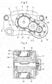
- Fig. 1 illustrates an electric brake system for a vehicle in which an electric linear motion actuator 1 according to the embodiment of the present invention is used.
- the electric brake system includes a caliper body 6 having opposed pieces 3 and 4 coupled together through a bridge 5 so as to be opposed to each other through a brake disk 2 configured to rotate together with a wheel, a pair of right and left friction pads 7 and 8 arranged, respectively, between the opposed piece 3 and the brake disk 2 and between the opposed piece 4 and the brake disk 2, and the electric linear motion actuator 1, incorporated in the opposed piece 3.
- the caliper body 6 is supported by a mount 9 (see Fig. 2 ) fixed to a knuckle (not shown) supporting the wheel so as to be slidable in the axial direction of the brake disk 2.
- the friction pads 7 and 8 are also supported so as to be movable in the axial direction of the brake disk 2.
- the electric linear motion actuator 1 includes an electric motor 10, a motion conversion mechanism 11 for converting the torque of the electric motor 10 to a linear driving force, and a load sensor 12 for detecting the magnitude of the pressing force applied to the brake disk 2.
- the electric motor 10 includes a rotor 13 and a stator 14.
- the rotor 13 is constituted by a motor shaft 16 rotatably supported by bearings 15, and a rotor core 17 fixed to the motor shaft 16.
- the stator 14 includes a plurality of teeth 18 circumferentially equidistantly spaced apart from each other so as to surround the rotor core 17, and electromagnetic coils 19 wound around the respective teeth 18.
- the stator 14 generates torque in the rotor 13 due to the electromagnetic force generated between the teeth 18 and the rotor core 17 when the electromagnetic coils 19 are energized.
- the magnitude of the torque generated in the rotor core 13 at this time corresponds to the driving electric current flowing in the electromagnetic coils 19.
- the magnitude of the torque of the electric motor 10 is substantially proportional to the driving current flowing in the electromagnetic coils 19, so that as the electric current applied to the electromagnetic coils 19 monotonically increases, the torque generated in the rotor 13 monotonically increases.
- the magnitude of the torque generated in the rotor 13 is not completely constant, but slightly increases and decreases according to the rotation phase of the rotor 13. Namely, during one rotation of the rotor 13 relative to the stator 14, as the rotor core 17 rotates relative to the teeth 18, the torque generated in the rotor 13 becomes maximum at first rotation phases of the rotor 13, and becomes minimum at second rotation phases of the rotor 13 which alternate with the first rotation phases.
- the motion conversion mechanism 11 includes a rotary shaft 20 arranged so as to be parallel to the electric motor 10.
- a gear 21 is attached to the rotary shaft 20.
- the gear 21 meshes with a gear 23 attached to the motor shaft 16 of the electric motor 10. Therefore, the torque generated in the electric motor 10 is transmitted to the gear 23, the intermediate gear 22, and the gear 21 so as to be input to the rotary shaft 20.
- the motion conversion mechanism 11 includes, besides the rotary shaft 20, to which the torque of the electric motor 10 is input, an outer ring member 24 arranged coaxially with the rotary shaft 20 so as to surround the rotary shaft 20, a plurality of planetary rollers 25 kept in contact, from radially outward, with the outer periphery of the rotary shaft 20 and, from radially inward, with the inner periphery of the outer ring member 24, and a carrier 26 retaining the planetary rollers 25 such that the respective planetary rollers 25 are rotatable about their axes while revolving around the rotary shaft 20.
- the outer ring member 24 is received in a receiving hole 27 formed in the opposed piece 3, and is axially movably supported by the inner surface of the receiving hole 27.
- An engagement rib 28 is formed at the axially front end of the outer ring member 24.
- the friction pad 7 is formed in its back surface with an engagement recess 29 in which the engagement rib 28 engages.
- the outer ring member 24 is rotationally fixed in position due to the engagement of the engagement rib 28 in the engagement recess 29.
- the planetary rollers 25 are arranged so as to be circumferentially spaced apart from each other.
- the planetary rollers 25 are kept in rolling contact with the outer periphery of the rotary shaft 20 and the inner periphery of the outer ring member 24.
- the outer periphery of the rotary shaft 20 is a cylindrical surface.
- the respective planetary rollers 25 rotate about their axes while revolving around the rotary shaft 20, between the rotary shaft 20 and the outer ring member 24. Namely, the respective planetary rollers 25 rotate about their axes under the rotational force transmitted from the outer periphery of the rotary shaft 20, and simultaneously revolve around the rotary shaft 20 by rolling on the inner periphery of the outer ring member 24.
- the outer ring 24 is formed on its inner periphery with a helical rib 30.
- the helical rib 30 extends obliquely relative to the circumferential direction.
- Each planetary roller 25 is formed in its outer periphery with circumferential grooves 31 in which the helical rib 30 engages.
- the helical rib 30 is guided by the circumferential grooves 31 so that the outer ring member 24 and the planetary rollers 25 move in the axial direction relative to each other.
- the circumferential grooves 31, having a 0 degree lead angle are formed on the outer periphery of each planetary roller 25, the circumferential grooves 31 may be replaced by a helical groove having a lead angle different from that of the helical rib 30.
- the carrier 26 includes a plurality of carrier pins 26A axially extending through the centers of the respective planetary rollers 25, an annular carrier plate 26C through which the axially front ends of the respective carrier pins 26A are coupled to each other, and an annular carrier body 26B through which the axially rear ends of the respective carrier pins 26A are coupled to each other.
- the carrier pins 26A support the respective planetary rollers 25 through bearings 32 such that the respective planetary rollers 25 are rotatable about their axes.
- Radially compressible ring springs 33 are attached to both ends of the respective carrier pins 26A so as to be wrapped around all of the circumferentially spaced apart carrier pins 26A.
- the respective carrier pins 26A are radially inwardly biased by the radially compressible ring springs 33, and this biasing force presses the respective planetary rollers 25 against the outer periphery of the rotary shaft 20, thereby preventing the slippage between the rotary shaft 20 and the respective planetary rollers 25.
- a slide bearing 34 is attached to the inner periphery of the carrier body 26B.
- the carrier body 26B is supported through the slide bearing 34 by the rotary shaft 20 so as to be rotatable relative to the rotary shaft 20.
- Thrust bearings 35 are incorporated between the carrier body 26B and the respective planetary rollers 25 to support the respective planetary rollers 25 so as to be rotatable about their axes.
- the carrier plate 26C and the carrier body 26B are coupled to each other through coupling rods 36 axially extending between the respective adjacent planetary rollers 25 so that the carrier plate 26C and the carrier body 26B rotate together.
- the load sensor 12 includes an annular plate-shaped flange member 40 and a supporting member 41 axially opposed to each other, a magnetic target 42 generating a magnetic field, and a magnetic sensor element 43 for detecting the strength of the magnetic field.
- the magnetic target 42 is fixed to the flange member 40
- the magnetic sensor element 43 is fixed to the supporting member 41.
- the magnetic target 42 and the magnetic sensor element 43 are opposed to each other such that the output from the magnetic sensor element 43 changes when the flange member 40 is deflected under an axial load applied to the flange member 40. As illustrated in Fig.
- the magnetic target 42 is constituted by two permanent magnets 44 magnetized in a direction orthogonal to the direction in which the magnetic target 42 and the magnetic sensor element 43 are displaced relative to each other, and arranged such that the north pole of one of the two permanent magnets 44 is adjacent to the south pole of the other permanent magnet 44.
- the magnetic sensor element 43 is arranged in the vicinity of the boundary between the adjacent magnetic poles of the respective two permanent magnets 44, constituting the magnetic target 42.
- the electric linear motion actuator 1 further includes, between the carrier 26 and the flange member 40, a spacer 45 configured to revolve around the rotary shaft 20 together with the carrier 26, and a thrust bearing 46 through which axial load is transmitted between the spacer 45 and the flange member 40.
- Rolling bearings 47 are incorporated inside the inner periphery of the flange member 40 to rotatably support the rotary shaft 20.
- snap rings 48 and 49 are attached to the inner periphery of the receiving hole 27 to engage, respectively, with the outer peripheral edge of the flange member 40 and with the outer peripheral edge of the supporting member 41, thereby restricting the axially forward and rearward movements of the load sensor 12.
- This load sensor 12 axially supports the carrier body 26B through the spacer 45 and the thrust bearing 46, thereby restricting the axially rearward movement of the carrier 26.
- a snap ring 50 attached to the axially front end of the rotary shaft 20 restricts the axially forward movement of the carrier 26. Namely, both of the axially forward and rearward movements of the carrier 26 are restricted, and since the planetary rollers 25 are retained by the carrier 26, the axially forward and rearward movements of the respective planetary rollers 25 are also kept restricted.
- the motion conversion mechanism 11 converts the torque of the electric motor 10 to the axial linear driving force of the outer ring member 24, and the friction pad 7 is pressed against the brake disk 2 by the outer ring member 24, thereby applying pressing force to the brake disk 2.
- the outer ring member 24 receives an axial reaction force from the brake disk 2 through the friction pad 7, and this reaction force is transmitted to the flange member 40 through the planetary rollers 25, the carrier 26, the spacer 45, and the thrust bearing 46.
- the flange member 40 is deflected axially rearwardly by the reaction force, so that the magnetic target 42 and the magnetic sensor element 43 are displaced relative to each other.
- the output signal from the magnetic sensor element 43 changes according to this relative displacement, thus making it possible to detect the magnitude of the pressing force applied to the break disk 2 on the basis of the output signal from the magnetic sensor element 43.
- the electric motor 10 is connected to a motor control device 51 illustrated in Fig. 7 .
- the motor control device 51 controls the driving electric current applied to the electric motor 10 on the basis of the magnitude of the pressing force detected by the load sensor 12.
- the motor control device 51 is configured to receive a load command value F from a brake ECU 52, a signal indicative of the magnitude of the pressing force from the load sensor 12, and a signal indicative of the rotation phase of the rotor 13 of the electric motor 10 from a phase sensor 53.
- the brake ECU 52 is an electronic control unit configured to control the above-described electric brake system and an additional similar electric brake system or systems mounted to other vehicle wheels, on the basis of, for example, how much the driver of the vehicle operates the brake pedal.
- the phase sensor 53 is, for example, a power supply unit which estimates the rotation phase of the rotor 13 on the basis of the line voltage between lines through which electric power is supplied to the electric motor 10.
- the phase sensor 53 may be a resolver or a hall element incorporated in the electric motor 10.
- the electric current applied to the electric motor 10 is controlled taking into account the hysteresis property of the motion conversion mechanism 11. This control is described below in detail.
- Hysteresis occurs in the motion conversion mechanism 11 when the pressing force applied to the brake disk 2 from the outer ring member 24 changes.
- Hysteresis is a phenomenon in which when the pressing force applied to the brake disk 2 from the outer ring member 24 while the torque of the electric motor 10 is increasing is identical in magnitude to the pressing force while the torque of the electric motor 10 is decreasing, the torque of the electric motor 10 necessary to generate the former pressing force is not identical in magnitude to, but is larger in magnitude than, the torque necessary to generate the latter pressing force.
- Such hysteresis mainly arises from the frictional forces generated in the motion conversion mechanism 11.
- the above motor control device 51 is configured to control the electric current applied to the electric motor 10 when the pressing force applied to the brake disk 2 is to be maintained, such that, first, the torque of the electric motor 10 increases until the pressing force detected by the load sensor 12 reaches a predetermined value larger than a target value, and then the torque of the electric motor 10 decreases until the pressing force detected by the load sensor 12 reaches the target value.
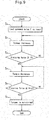
- the motor control device 51 is configured to control the electric current applied to the electric motor 10 when the load command value F is input to the motor control device 51 from the brake ECU 52 (step S 1 ), such that, first, the torque of the electric motor 10 increases until the pressing force detected by the load sensor 12 reaches a value (F+df), i.e. a value larger than the load command value F by a predetermined offset value df (steps S 2 and S 3 ), second, the torque of the electric motor 10 decreases until the pressing force detected by the load sensor 12 reaches the load command value F (steps S 4 and S 5 ), and third, the torque of the electric motor 10 is maintained (step S 6 ).
- the offset value df is a predetermined minute value sufficiently small compared to the load command value F.
- the torque of the electric motor 10 when the pressing force has reached the load command value F while the torque is decreasing as shown by straight line L 3 is not identical in magnitude to, but is smaller in magnitude by ⁇ T than, the torque of the electric motor 10 when the pressing force has reached the same load command value F while the torque is increasing as shown by straight line L 1 (due to the hysteresis property of the motion conversion mechanism 11).
- the motor control device 51 controls the electric current applied to the electric motor 10 when the pressing force detected by the load sensor 12 is maintained at the load command value F, such that the rotor 13 stops, among the above-mentioned first rotation phases of the rotor 13, at which the torque generated in the rotor 13 becomes maximum during one rotation of the rotor 13 relative to the stator 14, at the rotation phase which is the closest to the rotation phase where the pressing force coincides with the load command value F.
- the motor control device 51 controls the driving electric current applied to the electric motor 10 such that the rotor 13 stops not at the rotation phase where the pressing force detected by the load sensor 12 completely coincides with the load command value F, but at one of the first rotation phases closest to the rotation phase where the pressing force coincides with the load command value F.
- the above control by which the rotor 13 is stopped at one of the first rotation phases may be performed only if the load command value F is larger than a predetermined threshold value. By doing so, even if the load command value F is relatively small, it is possible to obtain stable pressing force.
- the motor control device 51 may be configured to control the electric current applied to the electric motor 10 when the load command value F is input to the motor control device 51 from the brake ECU 52 (step S 1 ), such that, first, the torque of the electric motor 10 increases until the pressing force detected by the load sensor 12 reaches the load command value F (steps S 2 and S 3 ), second, the torque of the electric motor 10 decreases until the pressing force detected by the load sensor 12 reaches a value (F-df), i.e. a value smaller by a predetermined offset value df than the load command value F (steps S 4 and S 5 ), and third, the torque of the electric motor 10 is maintained (step S 6 ).
- a value (F-df) i.e. a value smaller by a predetermined offset value df than the load command value F
- the torque of the electric motor 10 when the pressing force has reached the target value (F-df) while the torque is decreasing along straight line L 3 is not identical in magnitude to, but is smaller in magnitude by ⁇ T than, the torque when the pressing force has reached the same target value (F-df) while the torque is increasing along straight line L 1 (due to the hysteresis property of the motion conversion mechanism 11).
- the motor control device 51 controls the electric current applied to the electric motor 10 when the pressing force detected by the load sensor 12 is to be maintained at the target value, which is smaller by the predetermined offset value df than the load command value F, such that the rotor 13 stops at one of the first rotation phases of the rotor 13 closest to the rotation phase where the pressing force coincides with the target value (F-df).
- the above control by which the rotor 13 is stopped at one of the first rotation phases may be performed only if the target value (F-df) of the pressing force is larger than a predetermined threshold value. By doing so, even if the target value of the pressing force is relatively small, it is possible to obtain stable pressing force.
- a planetary roller mechanism which includes a rotary shaft 20 to which the torque of the electric motor 10 is input, planetary rollers 25 kept in rolling contact with the cylindrical surface of the outer periphery of the rotary shaft 20, an outer ring member 24 arranged so as to surround the planetary rollers 25, a helical rib 30 formed on the inner periphery of the outer ring member 24, and helical grooves or circumferential grooves 31 formed in the outer peripheries of the planetary rollers 25 such that the helical rib 30 engages in the helical grooves or the circumferential grooves 31.
- the above motor control device 51 can control the electric current applied to the electric motor 10 such that the work that the torque generated in the electric motor 10 increases and then decreases is performed at predetermined time intervals.
- the motor control device 51 can calculate the correspondence relation (positive efficiency) between the electric current applied to the electric motor 10 when the torque generated in the electric motor 10 increases and the pressing force applied to the brake disk 2 at this time, and the correspondence relation (reverse efficiency) between the electric current applied to the electric motor 10 when the torque generated in the electric motor 10 decreases and the pressing force applied to the brake disk 2 at this time, and can remember the correspondence relations.
- the motor control device 51 can control the electric current applied to the electric motor 10 on the basis of the respective correspondence relations remembered by the electric motor 10.
- the calculation and remembrance of the positive efficiency and the reverse efficiency by the motor control device 51 may be performed right after the motor control device 51 is turned on.
- the electric linear motion actuator of the above embodiment includes a planetary roller mechanism as the motion conversion mechanism 11 for converting the torque of the electric motor 10 to the linear driving force of the linear motion member (outer ring member 24).
- the present invention may also be applied to an electric linear motion actuator including a different motion conversion mechanism 11 (such as a sliding screw mechanism, a ball screw mechanism, or ball-ramp mechanism).
- a different motion conversion mechanism 11 such as a sliding screw mechanism, a ball screw mechanism, or ball-ramp mechanism.
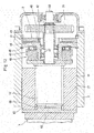
- Fig. 12 illustrates an electric linear motion actuator in which a sliding screw mechanism is used as the motion conversion mechanism 11.
- elements corresponding to those of the above embodiment are denoted by identical numerals, and their description is omitted.
- the electric linear motion actuator of Fig. 12 includes a rotary shaft 61 to which the torque of the electric motor 10 is input, a threaded shaft 62 configured to rotate together with the rotary shaft 61, a nut 63 kept in threaded engagement with the threaded shaft 62, and the load sensor 12 arranged axially rearward of the nut 63.
- the threaded shaft 62 is a shaft member formed on its outer periphery with an external thread 64.
- the nut 63 is a tubular member formed on its inner periphery with an internal thread 65.
- the external thread 64 and the internal thread 65 are in frictional contact with each other.
- the external thread 64 and the internal thread 65 may be, for example, trapezoidal threads each having a trapezoidal section.
- the nut 63 is axially slidably received in the receiving hole 27, formed in the opposed piece 3 of the caliper body 6, while rotationally fixed to the caliper body 6.
- a spacer 45 is provided at the axially rear end of the threaded shaft 62 so as to be rotatable together with the threaded shaft 62, and is supported by the load sensor 12 through a thrust bearing 46.
- the load sensor 12 restricts the axially rearward movement of the nut 63 by axially supporting the nut 63 through the spacer 45, the thrust bearing 46, and the threaded shaft 62.
Landscapes
- Engineering & Computer Science (AREA)
- General Engineering & Computer Science (AREA)
- Mechanical Engineering (AREA)
- Transportation (AREA)
- Power Engineering (AREA)
- Braking Arrangements (AREA)
- Braking Systems And Boosters (AREA)
- Transmission Devices (AREA)
- Connection Of Motors, Electrical Generators, Mechanical Devices, And The Like (AREA)
Claims (7)
- Elektrisches Linearbewegungsstellglied, umfassend:einen Elektromotor (10), der ein Drehmoment in Entsprechung zu einem an dem Elektromotor (10) angelegten Antriebsstrom erzeugen kann,einen Bewegungswandlungsmechanismus (11), der konfiguriert ist zum Wandeln des durch den Elektromotor (10) erzeugten Drehmoments zu einer linearen Antriebskraft eines Linearbewegungsglieds (24) derart, dass durch das Linearbewegungsglied (24) eine Drückkraft auf ein Zielglied (2) ausgeübt wird,einen Lastsensor (12), der konfiguriert ist zum Erfassen der Größe der auf das Zielglied (2) ausgeübten Drückkraft, undeine Motorsteuereinrichtung (51), die konfiguriert ist zum Steuern des an dem Elektromotor (10) angelegten Antriebsstroms basierend auf der Größe der durch den Lastsensor (12) erfassten Drückkraft.wobei der Bewegungswandlungsmechanismus (11) einen Mechanismus umfasst, der eine Hystereseeigenschaft aufweist, sodass die Größe des Drehmoments des Elektromotors (10), wenn die Drückkraft eine beliebige Größe aufweist, während sich das Drehmoment vergrößert (L1), nicht identisch sondern höher ist als die Größe des Drehmoments, wenn die Drückkraft die beliebige Größe aufweist, während sich das Drehmoment verkleinert (L3),dadurch gekennzeichnet, dassdie Motorsteuereinrichtung (51) konfiguriert ist zum Steuern des an dem Elektromotor (10) angelegten Stroms, wenn die an dem Zielglied (2) angelegte Drückkraft aufrechtzuerhalten ist, sodass das Drehmoment des Elektromotors (10) größer wird, bis die durch den Lastsensor (12) erfasste Drückkraft einen vorbestimmten Wert, der größer als der Zielwert ist, erreicht, und dann das Drehmoment des Elektromotors (10) kleiner wird, bis die durch den Lastsensor (12) erfasste Drückkraft den Zielwert erreicht.
- Elektrisches Linearbewegungsstellglied nach Anspruch 1, wobei der Zielwert gleich einem Lastbefehlswert (F) ist, der von außen (52) in die Motorsteuereinrichtung (51) eingegeben wird, und wobei der vorbestimmte Wert gleich einem Wert ist, der um einen vorbestimmten Versatzwert (df) größer als der Lastbefehlswert (F) ist.
- Elektrisches Linearbewegungsstellglied nach Anspruch 1, wobei der Zielwert gleich einem Wert ist, der um einen vorbestimmten Versatzwert (df) kleiner ist als ein Lastbefehlswert (F), der von außen (52) in die Motorsteuereinrichtung (51) eingegeben wird, und wobei der vorbestimmte Wert gleich dem Lastbefehlswert (F) ist.
- Elektrisches Linearbewegungsglied nach einem der Ansprüche 1 bis 3, wobei der Elektromotor (10) einen drehbar gehaltenen Rotor (13) und einen Stator (14), durch den ein Drehmoment in dem Rotor (13) zu erzeugen ist, umfasst,
wobei der Rotor (13) und der Stator (14) derart konfiguriert sind, dass während einer Drehung des Rotors (13) relativ zu dem Stator (14) das in dem Rotor (13) erzeugte Drehmoment in ersten Drehphasen des Rotors maximal wird und das in dem Rotor (13) erzeugte Drehmoment in zweiten Drehphasen, die mit den ersten Drehphasen alternieren, minimal wird,
wobei ein Phasensensor (53) vorgesehen ist, der für das Erfassen der Drehphase des Rotors (13) konfiguriert ist, und
wobei die Motorsteuereinrichtung (51) konfiguriert ist zum Steuern des an dem Elektromotor (10) angelegten Antriebsstroms, wenn die durch den Lastsensor (12) erfasste Drückkraft bei dem Zielwert gehalten wird, sodass der Rotor (13) an einer ersten Drehphase stoppt, die der Drehphase, bei der die Drückkraft dem Zielwert entspricht, am nächsten ist. - Elektrisches Linearbewegungsglied nach Anspruch 4, wobei die Motorsteuereinrichtung (51) konfiguriert ist, um die Steuerung gemäß Anspruch 4 nur dann durchzuführen, wenn der Zielwert der Drückkraft größer als ein vorbestimmter Schwellwert ist.
- Elektrisches Linearbewegungsglied nach einem der Ansprüche 1 bis 5, wobei der Bewegungswandlungsmechanismus (11) einen Planetenrollenmechanismus umfasst, der umfasst:eine Drehwelle (20), zu der das Drehmoment des Elektromotors (10) einzugeben ist,ein Außenringglied (24), das koaxial mit der Drehwelle (20) angeordnet ist und die Drehwelle (20) umgibt,eine Vielzahl von Planetenrollen (25), die in Kontakt mit einem Außenumfang der Drehwelle (20) und mit einem Innenumfang des Außenringglieds (24) gehalten werden, undeinen Träger (26), der die Planetenrollen (25) derart hält, dass die Planetenrollen (25) um Achsen der entsprechenden Planetenrollen (25) gedreht werden können, während sie sich um die Drehwelle (20) drehen,wobei eine spiralförmige Rippe (30) an dem Innenumfang des Außenringglieds (24) ausgebildet ist, undeine spiralförmige Nut oder Umfangsnut (31) an einem Außenumfang jeder der Planetenrollen (25) ausgebildet ist, sodass die spiralförmige Rippe (30) in die spiralförmige Nut oder Umfangsnut (31) eingreift.
- Elektrisches Bremssystem, umfassend:eine Bremsscheibe (2), die konfiguriert ist für eine Drehung zusammen mit einem Rad,einen Bremsbelag (7), undein elektrisches Linearbewegungsstellglied, das konfiguriert ist zum Drücken des Bremsbelags (7) gegen die Bremsscheibe (2),wobei das elektrische Linearbewegungsstellglied das elektrische Linearbewegungsstellglied gemäß einem der Ansprüche 1 bis 6 ist und wobei das Zielglied die Bremsscheibe (2) ist.
Applications Claiming Priority (2)
| Application Number | Priority Date | Filing Date | Title |
|---|---|---|---|
| JP2013105153A JP6080682B2 (ja) | 2013-05-17 | 2013-05-17 | 電動式直動アクチュエータおよび電動ブレーキ装置 |
| PCT/JP2014/062153 WO2014185292A1 (ja) | 2013-05-17 | 2014-05-02 | 電動式直動アクチュエータおよび電動ブレーキ装置 |
Publications (3)
| Publication Number | Publication Date |
|---|---|
| EP2999111A1 EP2999111A1 (de) | 2016-03-23 |
| EP2999111A4 EP2999111A4 (de) | 2016-08-31 |
| EP2999111B1 true EP2999111B1 (de) | 2019-11-06 |
Family
ID=51898271
Family Applications (1)
| Application Number | Title | Priority Date | Filing Date |
|---|---|---|---|
| EP14798431.4A Active EP2999111B1 (de) | 2013-05-17 | 2014-05-02 | Elektrisches lineares stellglied und elektrische bremsvorrichtung |
Country Status (5)
| Country | Link |
|---|---|
| US (1) | US9797462B2 (de) |
| EP (1) | EP2999111B1 (de) |
| JP (1) | JP6080682B2 (de) |
| CN (2) | CN108177642B (de) |
| WO (1) | WO2014185292A1 (de) |
Families Citing this family (21)
| Publication number | Priority date | Publication date | Assignee | Title |
|---|---|---|---|---|
| JP6352202B2 (ja) * | 2015-02-16 | 2018-07-04 | 株式会社ミツバ | ブレーキ用アクチュエータおよびブレーキ装置 |
| FR3045754B1 (fr) * | 2015-12-17 | 2019-06-14 | Foundation Brakes France | Actionneur electromecanique a encombrement reduit pour frein a disque |
| EP3473891A4 (de) * | 2016-06-16 | 2019-06-19 | NTN Corporation | Elektrisches lineares stellglied und elektrische bremsvorrichtung |
| JP2018002105A (ja) * | 2016-07-08 | 2018-01-11 | Ntn株式会社 | 電動式直動アクチュエータ |
| JP6752668B2 (ja) * | 2016-09-28 | 2020-09-09 | Ntn株式会社 | 電動ブレーキ装置 |
| JP2018070083A (ja) * | 2016-11-04 | 2018-05-10 | Ntn株式会社 | 電動ブレーキ装置 |
| JP6506236B2 (ja) * | 2016-11-28 | 2019-04-24 | トヨタ自動車株式会社 | 電動ブレーキ制御装置 |
| US10975940B2 (en) * | 2017-08-24 | 2021-04-13 | Eaton Intelligent Power Limited | Actuator and method |
| JP6900881B2 (ja) * | 2017-11-20 | 2021-07-07 | トヨタ自動車株式会社 | 電動ブレーキ制御装置 |
| DE102018210511A1 (de) * | 2018-06-27 | 2020-01-02 | Robert Bosch Gmbh | Verfahren zur Ermittlung der Bremskraft in einer elektromechanischen Bremsvorrichtung mit einem elektrischen Bremsmotor |
| JP7115934B2 (ja) | 2018-08-21 | 2022-08-09 | 株式会社デンソー | モータ装置 |
| US10876587B2 (en) * | 2019-03-28 | 2020-12-29 | Keyang Electric Machinery Co., Ltd. | Actuator assembly with integrated housing for electromechanical parking brake |
| JP7201807B2 (ja) * | 2019-06-27 | 2023-01-10 | アルプスアルパイン株式会社 | 操作装置 |
| CN111002966B (zh) * | 2019-12-24 | 2021-06-04 | 精诚工科汽车系统有限公司 | 车辆制动控制方法、装置及线控助力制动系统 |
| CN112810586A (zh) * | 2021-01-20 | 2021-05-18 | 清华大学 | 一种商用车制动器促动模组及制动系统 |
| JP7800336B2 (ja) * | 2022-08-01 | 2026-01-16 | 株式会社デンソー | 車両用制動装置 |
| JP7779217B2 (ja) * | 2022-09-01 | 2025-12-03 | 株式会社デンソー | 車両用制動装置 |
| JP7797988B2 (ja) * | 2022-09-01 | 2026-01-14 | 株式会社デンソー | 車両用制動装置 |
| JP7835139B2 (ja) * | 2022-09-22 | 2026-03-25 | 株式会社デンソー | 車両用制動装置 |
| US20250010835A1 (en) * | 2023-07-06 | 2025-01-09 | ZF Active Safety US Inc. | Electromechanical brake having a force sensor |
| JP2025075722A (ja) * | 2023-10-31 | 2025-05-15 | 株式会社アドヴィックス | 電動制動装置 |
Family Cites Families (22)
| Publication number | Priority date | Publication date | Assignee | Title |
|---|---|---|---|---|
| US4995483A (en) * | 1989-12-18 | 1991-02-26 | Aircraft Braking Systems Corporation | Motor position feedback controlled electrically actuated aircraft brake |
| DE4317846A1 (de) * | 1993-05-28 | 1994-12-01 | Wabco Vermoegensverwaltung | Verfahren zur Einstellung eines Bremswertes auf einen Soll-Bremswert |
| DE19742920A1 (de) * | 1997-09-29 | 1999-04-01 | Itt Mfg Enterprises Inc | Verfahren zum Aufbringen definierter Betätigungskräfte |
| JP2000016279A (ja) * | 1998-06-30 | 2000-01-18 | Tokico Ltd | 電動ブレーキ装置 |
| JP4590709B2 (ja) * | 2000-09-28 | 2010-12-01 | 株式会社デンソー | 車両用ブレーキ装置 |
| JP2004122838A (ja) * | 2002-08-07 | 2004-04-22 | Asmo Co Ltd | 電動駐車ブレーキ装置及び電動駐車ブレーキ装置の制御方法 |
| JP2004175203A (ja) * | 2002-11-27 | 2004-06-24 | Advics:Kk | 電動パーキングブレーキ装置 |
| US7104616B2 (en) * | 2003-07-02 | 2006-09-12 | Goodrich Corporation | Brake gain-based torque controller |
| JP2005067400A (ja) * | 2003-08-25 | 2005-03-17 | Advics:Kk | 電気ブレーキシステム |
| JP4342469B2 (ja) * | 2005-04-01 | 2009-10-14 | トヨタ自動車株式会社 | 車両用ブレーキの制御装置 |
| JP2008049800A (ja) * | 2006-08-24 | 2008-03-06 | Hitachi Ltd | 電動ブレーキ装置およびその制御方法 |
| JP4265633B2 (ja) * | 2006-09-15 | 2009-05-20 | トヨタ自動車株式会社 | 電動パーキングブレーキシステム |
| JP2009029294A (ja) * | 2007-07-27 | 2009-02-12 | Hitachi Ltd | 車両用ブレーキシステム |
| EP2214944B1 (de) * | 2007-10-24 | 2011-08-31 | Continental Teves AG & Co. oHG | Feststellbremse und verfahren zum betreiben derselben |
| JP2009220807A (ja) * | 2008-02-22 | 2009-10-01 | Hitachi Ltd | 自動車ブレーキ用モータ駆動装置 |
| US20090281702A1 (en) * | 2008-05-08 | 2009-11-12 | Cahill Eric D | Resolving stack closure of a position controlled electric brake system |
| EP2484935B1 (de) * | 2009-09-29 | 2019-11-06 | NTN Corporation | Elektrischer linearantrieb und elektrische scheibenbremse |
| JP5547547B2 (ja) * | 2010-05-14 | 2014-07-16 | Ntn株式会社 | 電動式直動アクチュエータおよび電動式ブレーキ装置 |
| JP5406155B2 (ja) * | 2010-10-06 | 2014-02-05 | 日立オートモティブシステムズ株式会社 | ディスクブレーキ装置 |
| JP5833405B2 (ja) * | 2011-10-11 | 2015-12-16 | Ntn株式会社 | 直動アクチュエータ用の磁気式荷重センサおよび直動アクチュエータ |
| JP6182314B2 (ja) * | 2013-01-08 | 2017-08-16 | Ntn株式会社 | 電動ブレーキ装置 |
| DE112014001471B4 (de) * | 2013-03-15 | 2022-02-17 | Advics Co., Ltd. | Elektrisches Bremssystem für ein Fahrzeug |
-
2013
- 2013-05-17 JP JP2013105153A patent/JP6080682B2/ja active Active
-
2014
- 2014-05-02 EP EP14798431.4A patent/EP2999111B1/de active Active
- 2014-05-02 US US14/889,872 patent/US9797462B2/en not_active Expired - Fee Related
- 2014-05-02 WO PCT/JP2014/062153 patent/WO2014185292A1/ja not_active Ceased
- 2014-05-02 CN CN201711392653.9A patent/CN108177642B/zh not_active Expired - Fee Related
- 2014-05-02 CN CN201480028722.6A patent/CN105228873B/zh not_active Expired - Fee Related
Non-Patent Citations (1)
| Title |
|---|
| None * |
Also Published As
| Publication number | Publication date |
|---|---|
| US9797462B2 (en) | 2017-10-24 |
| JP2014226007A (ja) | 2014-12-04 |
| EP2999111A1 (de) | 2016-03-23 |
| CN108177642B (zh) | 2020-08-11 |
| EP2999111A4 (de) | 2016-08-31 |
| US20160091039A1 (en) | 2016-03-31 |
| WO2014185292A1 (ja) | 2014-11-20 |
| CN105228873A (zh) | 2016-01-06 |
| JP6080682B2 (ja) | 2017-02-15 |
| CN105228873B (zh) | 2018-01-26 |
| CN108177642A (zh) | 2018-06-19 |
Similar Documents
| Publication | Publication Date | Title |
|---|---|---|
| EP2999111B1 (de) | Elektrisches lineares stellglied und elektrische bremsvorrichtung | |
| EP2928072B1 (de) | Elektrischer linearbewegungsaktuator | |
| EP3305609B1 (de) | Elektrisch angetriebene bremsvorrichtung | |
| EP2772659B1 (de) | Elektrischer aktuator mit direktwirkung und elektrische bremsvorrichtung | |
| EP2767812B1 (de) | Magnetischer lastsensor zur benützung in einem linearbewegungsaktuator und linearbewegungsaktuator | |
| EP2775170B1 (de) | Elektrischer linearbewegungsaktuator | |
| EP2738532B1 (de) | Magnetischer Lastsensor zur Verwendung in einem Linearbewegungsaktuator und ein Linearbewegungsaktuator | |
| EP2581623A1 (de) | Elektrische bremse für ein fahrzeug | |
| EP2662587B1 (de) | Elektrische bremsvorrichtung | |
| JP5413719B2 (ja) | 電動ブレーキ装置 | |
| EP2944936B1 (de) | Magnetischer lastsensor und elektrische bremsvorrichtung | |
| JP2016217415A (ja) | パーキング機能付き電動ブレーキ装置 | |
| JP6505399B2 (ja) | 車両ブレーキ装置用荷重センサ、電動式直動アクチュエータおよび電動ブレーキ装置 | |
| JP6258531B2 (ja) | 電動式直動アクチュエータおよび電動ブレーキ装置 | |
| JP2015044479A (ja) | 車両用操舵装置 | |
| JP6779673B2 (ja) | 電動式直動アクチュエータ | |
| JP2014088911A (ja) | 電動式直動アクチュエータ | |
| JP5772771B2 (ja) | 渦電流式減速装置 |
Legal Events
| Date | Code | Title | Description |
|---|---|---|---|
| PUAI | Public reference made under article 153(3) epc to a published international application that has entered the european phase |
Free format text: ORIGINAL CODE: 0009012 |
|
| 17P | Request for examination filed |
Effective date: 20151209 |
|
| AK | Designated contracting states |
Kind code of ref document: A1 Designated state(s): AL AT BE BG CH CY CZ DE DK EE ES FI FR GB GR HR HU IE IS IT LI LT LU LV MC MK MT NL NO PL PT RO RS SE SI SK SM TR |
|
| AX | Request for extension of the european patent |
Extension state: BA ME |
|
| DAX | Request for extension of the european patent (deleted) | ||
| A4 | Supplementary search report drawn up and despatched |
Effective date: 20160801 |
|
| RIC1 | Information provided on ipc code assigned before grant |
Ipc: F16H 25/20 20060101ALI20160726BHEP Ipc: H02P 29/00 20160101AFI20160726BHEP Ipc: B60T 13/74 20060101ALI20160726BHEP |
|
| GRAP | Despatch of communication of intention to grant a patent |
Free format text: ORIGINAL CODE: EPIDOSNIGR1 |
|
| STAA | Information on the status of an ep patent application or granted ep patent |
Free format text: STATUS: GRANT OF PATENT IS INTENDED |
|
| INTG | Intention to grant announced |
Effective date: 20190613 |
|
| GRAS | Grant fee paid |
Free format text: ORIGINAL CODE: EPIDOSNIGR3 |
|
| GRAA | (expected) grant |
Free format text: ORIGINAL CODE: 0009210 |
|
| STAA | Information on the status of an ep patent application or granted ep patent |
Free format text: STATUS: THE PATENT HAS BEEN GRANTED |
|
| AK | Designated contracting states |
Kind code of ref document: B1 Designated state(s): AL AT BE BG CH CY CZ DE DK EE ES FI FR GB GR HR HU IE IS IT LI LT LU LV MC MK MT NL NO PL PT RO RS SE SI SK SM TR |
|
| REG | Reference to a national code |
Ref country code: GB Ref legal event code: FG4D |
|
| REG | Reference to a national code |
Ref country code: AT Ref legal event code: REF Ref document number: 1200167 Country of ref document: AT Kind code of ref document: T Effective date: 20191115 Ref country code: CH Ref legal event code: EP |
|
| REG | Reference to a national code |
Ref country code: IE Ref legal event code: FG4D |
|
| REG | Reference to a national code |
Ref country code: DE Ref legal event code: R096 Ref document number: 602014056399 Country of ref document: DE |
|
| REG | Reference to a national code |
Ref country code: NL Ref legal event code: MP Effective date: 20191106 |
|
| REG | Reference to a national code |
Ref country code: LT Ref legal event code: MG4D |
|
| PG25 | Lapsed in a contracting state [announced via postgrant information from national office to epo] |
Ref country code: NL Free format text: LAPSE BECAUSE OF FAILURE TO SUBMIT A TRANSLATION OF THE DESCRIPTION OR TO PAY THE FEE WITHIN THE PRESCRIBED TIME-LIMIT Effective date: 20191106 Ref country code: BG Free format text: LAPSE BECAUSE OF FAILURE TO SUBMIT A TRANSLATION OF THE DESCRIPTION OR TO PAY THE FEE WITHIN THE PRESCRIBED TIME-LIMIT Effective date: 20200206 Ref country code: FI Free format text: LAPSE BECAUSE OF FAILURE TO SUBMIT A TRANSLATION OF THE DESCRIPTION OR TO PAY THE FEE WITHIN THE PRESCRIBED TIME-LIMIT Effective date: 20191106 Ref country code: NO Free format text: LAPSE BECAUSE OF FAILURE TO SUBMIT A TRANSLATION OF THE DESCRIPTION OR TO PAY THE FEE WITHIN THE PRESCRIBED TIME-LIMIT Effective date: 20200206 Ref country code: PL Free format text: LAPSE BECAUSE OF FAILURE TO SUBMIT A TRANSLATION OF THE DESCRIPTION OR TO PAY THE FEE WITHIN THE PRESCRIBED TIME-LIMIT Effective date: 20191106 Ref country code: LT Free format text: LAPSE BECAUSE OF FAILURE TO SUBMIT A TRANSLATION OF THE DESCRIPTION OR TO PAY THE FEE WITHIN THE PRESCRIBED TIME-LIMIT Effective date: 20191106 Ref country code: GR Free format text: LAPSE BECAUSE OF FAILURE TO SUBMIT A TRANSLATION OF THE DESCRIPTION OR TO PAY THE FEE WITHIN THE PRESCRIBED TIME-LIMIT Effective date: 20200207 Ref country code: SE Free format text: LAPSE BECAUSE OF FAILURE TO SUBMIT A TRANSLATION OF THE DESCRIPTION OR TO PAY THE FEE WITHIN THE PRESCRIBED TIME-LIMIT Effective date: 20191106 Ref country code: LV Free format text: LAPSE BECAUSE OF FAILURE TO SUBMIT A TRANSLATION OF THE DESCRIPTION OR TO PAY THE FEE WITHIN THE PRESCRIBED TIME-LIMIT Effective date: 20191106 Ref country code: PT Free format text: LAPSE BECAUSE OF FAILURE TO SUBMIT A TRANSLATION OF THE DESCRIPTION OR TO PAY THE FEE WITHIN THE PRESCRIBED TIME-LIMIT Effective date: 20200306 |
|
| PG25 | Lapsed in a contracting state [announced via postgrant information from national office to epo] |
Ref country code: RS Free format text: LAPSE BECAUSE OF FAILURE TO SUBMIT A TRANSLATION OF THE DESCRIPTION OR TO PAY THE FEE WITHIN THE PRESCRIBED TIME-LIMIT Effective date: 20191106 Ref country code: IS Free format text: LAPSE BECAUSE OF FAILURE TO SUBMIT A TRANSLATION OF THE DESCRIPTION OR TO PAY THE FEE WITHIN THE PRESCRIBED TIME-LIMIT Effective date: 20200306 Ref country code: HR Free format text: LAPSE BECAUSE OF FAILURE TO SUBMIT A TRANSLATION OF THE DESCRIPTION OR TO PAY THE FEE WITHIN THE PRESCRIBED TIME-LIMIT Effective date: 20191106 |
|
| PG25 | Lapsed in a contracting state [announced via postgrant information from national office to epo] |
Ref country code: AL Free format text: LAPSE BECAUSE OF FAILURE TO SUBMIT A TRANSLATION OF THE DESCRIPTION OR TO PAY THE FEE WITHIN THE PRESCRIBED TIME-LIMIT Effective date: 20191106 |
|
| PG25 | Lapsed in a contracting state [announced via postgrant information from national office to epo] |
Ref country code: CZ Free format text: LAPSE BECAUSE OF FAILURE TO SUBMIT A TRANSLATION OF THE DESCRIPTION OR TO PAY THE FEE WITHIN THE PRESCRIBED TIME-LIMIT Effective date: 20191106 Ref country code: ES Free format text: LAPSE BECAUSE OF FAILURE TO SUBMIT A TRANSLATION OF THE DESCRIPTION OR TO PAY THE FEE WITHIN THE PRESCRIBED TIME-LIMIT Effective date: 20191106 Ref country code: EE Free format text: LAPSE BECAUSE OF FAILURE TO SUBMIT A TRANSLATION OF THE DESCRIPTION OR TO PAY THE FEE WITHIN THE PRESCRIBED TIME-LIMIT Effective date: 20191106 Ref country code: DK Free format text: LAPSE BECAUSE OF FAILURE TO SUBMIT A TRANSLATION OF THE DESCRIPTION OR TO PAY THE FEE WITHIN THE PRESCRIBED TIME-LIMIT Effective date: 20191106 Ref country code: RO Free format text: LAPSE BECAUSE OF FAILURE TO SUBMIT A TRANSLATION OF THE DESCRIPTION OR TO PAY THE FEE WITHIN THE PRESCRIBED TIME-LIMIT Effective date: 20191106 |
|
| REG | Reference to a national code |
Ref country code: DE Ref legal event code: R097 Ref document number: 602014056399 Country of ref document: DE |
|
| REG | Reference to a national code |
Ref country code: AT Ref legal event code: MK05 Ref document number: 1200167 Country of ref document: AT Kind code of ref document: T Effective date: 20191106 |
|
| PG25 | Lapsed in a contracting state [announced via postgrant information from national office to epo] |
Ref country code: SK Free format text: LAPSE BECAUSE OF FAILURE TO SUBMIT A TRANSLATION OF THE DESCRIPTION OR TO PAY THE FEE WITHIN THE PRESCRIBED TIME-LIMIT Effective date: 20191106 Ref country code: SM Free format text: LAPSE BECAUSE OF FAILURE TO SUBMIT A TRANSLATION OF THE DESCRIPTION OR TO PAY THE FEE WITHIN THE PRESCRIBED TIME-LIMIT Effective date: 20191106 |
|
| PLBE | No opposition filed within time limit |
Free format text: ORIGINAL CODE: 0009261 |
|
| STAA | Information on the status of an ep patent application or granted ep patent |
Free format text: STATUS: NO OPPOSITION FILED WITHIN TIME LIMIT |
|
| 26N | No opposition filed |
Effective date: 20200807 |
|
| PG25 | Lapsed in a contracting state [announced via postgrant information from national office to epo] |
Ref country code: SI Free format text: LAPSE BECAUSE OF FAILURE TO SUBMIT A TRANSLATION OF THE DESCRIPTION OR TO PAY THE FEE WITHIN THE PRESCRIBED TIME-LIMIT Effective date: 20191106 Ref country code: AT Free format text: LAPSE BECAUSE OF FAILURE TO SUBMIT A TRANSLATION OF THE DESCRIPTION OR TO PAY THE FEE WITHIN THE PRESCRIBED TIME-LIMIT Effective date: 20191106 |
|
| PG25 | Lapsed in a contracting state [announced via postgrant information from national office to epo] |
Ref country code: MC Free format text: LAPSE BECAUSE OF FAILURE TO SUBMIT A TRANSLATION OF THE DESCRIPTION OR TO PAY THE FEE WITHIN THE PRESCRIBED TIME-LIMIT Effective date: 20191106 Ref country code: LI Free format text: LAPSE BECAUSE OF NON-PAYMENT OF DUE FEES Effective date: 20200531 Ref country code: CH Free format text: LAPSE BECAUSE OF NON-PAYMENT OF DUE FEES Effective date: 20200531 Ref country code: IT Free format text: LAPSE BECAUSE OF FAILURE TO SUBMIT A TRANSLATION OF THE DESCRIPTION OR TO PAY THE FEE WITHIN THE PRESCRIBED TIME-LIMIT Effective date: 20191106 |
|
| REG | Reference to a national code |
Ref country code: BE Ref legal event code: MM Effective date: 20200531 |
|
| GBPC | Gb: european patent ceased through non-payment of renewal fee |
Effective date: 20200502 |
|
| PG25 | Lapsed in a contracting state [announced via postgrant information from national office to epo] |
Ref country code: LU Free format text: LAPSE BECAUSE OF NON-PAYMENT OF DUE FEES Effective date: 20200502 |
|
| PG25 | Lapsed in a contracting state [announced via postgrant information from national office to epo] |
Ref country code: IE Free format text: LAPSE BECAUSE OF NON-PAYMENT OF DUE FEES Effective date: 20200502 Ref country code: GB Free format text: LAPSE BECAUSE OF NON-PAYMENT OF DUE FEES Effective date: 20200502 |
|
| PG25 | Lapsed in a contracting state [announced via postgrant information from national office to epo] |
Ref country code: BE Free format text: LAPSE BECAUSE OF NON-PAYMENT OF DUE FEES Effective date: 20200531 |
|
| PGFP | Annual fee paid to national office [announced via postgrant information from national office to epo] |
Ref country code: FR Payment date: 20210426 Year of fee payment: 8 Ref country code: DE Payment date: 20210413 Year of fee payment: 8 |
|
| PG25 | Lapsed in a contracting state [announced via postgrant information from national office to epo] |
Ref country code: TR Free format text: LAPSE BECAUSE OF FAILURE TO SUBMIT A TRANSLATION OF THE DESCRIPTION OR TO PAY THE FEE WITHIN THE PRESCRIBED TIME-LIMIT Effective date: 20191106 Ref country code: MT Free format text: LAPSE BECAUSE OF FAILURE TO SUBMIT A TRANSLATION OF THE DESCRIPTION OR TO PAY THE FEE WITHIN THE PRESCRIBED TIME-LIMIT Effective date: 20191106 Ref country code: CY Free format text: LAPSE BECAUSE OF FAILURE TO SUBMIT A TRANSLATION OF THE DESCRIPTION OR TO PAY THE FEE WITHIN THE PRESCRIBED TIME-LIMIT Effective date: 20191106 |
|
| PG25 | Lapsed in a contracting state [announced via postgrant information from national office to epo] |
Ref country code: MK Free format text: LAPSE BECAUSE OF FAILURE TO SUBMIT A TRANSLATION OF THE DESCRIPTION OR TO PAY THE FEE WITHIN THE PRESCRIBED TIME-LIMIT Effective date: 20191106 |
|
| REG | Reference to a national code |
Ref country code: DE Ref legal event code: R119 Ref document number: 602014056399 Country of ref document: DE |
|
| PG25 | Lapsed in a contracting state [announced via postgrant information from national office to epo] |
Ref country code: FR Free format text: LAPSE BECAUSE OF NON-PAYMENT OF DUE FEES Effective date: 20220531 |
|
| PG25 | Lapsed in a contracting state [announced via postgrant information from national office to epo] |
Ref country code: DE Free format text: LAPSE BECAUSE OF NON-PAYMENT OF DUE FEES Effective date: 20221201 |