EP2999115B1 - Système et procédé de prédistorsion numérique - Google Patents
Système et procédé de prédistorsion numérique Download PDFInfo
- Publication number
- EP2999115B1 EP2999115B1 EP15185373.6A EP15185373A EP2999115B1 EP 2999115 B1 EP2999115 B1 EP 2999115B1 EP 15185373 A EP15185373 A EP 15185373A EP 2999115 B1 EP2999115 B1 EP 2999115B1
- Authority
- EP
- European Patent Office
- Prior art keywords
- distortion
- radio
- radio unit
- digital
- data signal
- Prior art date
- Legal status (The legal status is an assumption and is not a legal conclusion. Google has not performed a legal analysis and makes no representation as to the accuracy of the status listed.)
- Active
Links
Images

Classifications
-
- H—ELECTRICITY
- H04—ELECTRIC COMMUNICATION TECHNIQUE
- H04B—TRANSMISSION
- H04B1/00—Details of transmission systems, not covered by a single one of groups H04B3/00 - H04B13/00; Details of transmission systems not characterised by the medium used for transmission
- H04B1/02—Transmitters
- H04B1/04—Circuits
- H04B1/0475—Circuits with means for limiting noise, interference or distortion
-
- H—ELECTRICITY
- H03—ELECTRONIC CIRCUITRY
- H03F—AMPLIFIERS
- H03F1/00—Details of amplifiers with only discharge tubes, only semiconductor devices or only unspecified devices as amplifying elements
- H03F1/32—Modifications of amplifiers to reduce non-linear distortion
- H03F1/3241—Modifications of amplifiers to reduce non-linear distortion using predistortion circuits
-
- H—ELECTRICITY
- H03—ELECTRONIC CIRCUITRY
- H03F—AMPLIFIERS
- H03F1/00—Details of amplifiers with only discharge tubes, only semiconductor devices or only unspecified devices as amplifying elements
- H03F1/32—Modifications of amplifiers to reduce non-linear distortion
- H03F1/3241—Modifications of amplifiers to reduce non-linear distortion using predistortion circuits
- H03F1/3247—Modifications of amplifiers to reduce non-linear distortion using predistortion circuits using feedback acting on predistortion circuits
-
- H—ELECTRICITY
- H03—ELECTRONIC CIRCUITRY
- H03F—AMPLIFIERS
- H03F1/00—Details of amplifiers with only discharge tubes, only semiconductor devices or only unspecified devices as amplifying elements
- H03F1/32—Modifications of amplifiers to reduce non-linear distortion
- H03F1/3241—Modifications of amplifiers to reduce non-linear distortion using predistortion circuits
- H03F1/3258—Modifications of amplifiers to reduce non-linear distortion using predistortion circuits based on polynomial terms
-
- H—ELECTRICITY
- H03—ELECTRONIC CIRCUITRY
- H03F—AMPLIFIERS
- H03F3/00—Amplifiers with only discharge tubes or only semiconductor devices as amplifying elements
- H03F3/189—High-frequency amplifiers, e.g. radio frequency amplifiers
- H03F3/19—High-frequency amplifiers, e.g. radio frequency amplifiers with semiconductor devices only
- H03F3/195—High-frequency amplifiers, e.g. radio frequency amplifiers with semiconductor devices only in integrated circuits
-
- H—ELECTRICITY
- H03—ELECTRONIC CIRCUITRY
- H03F—AMPLIFIERS
- H03F3/00—Amplifiers with only discharge tubes or only semiconductor devices as amplifying elements
- H03F3/20—Power amplifiers, e.g. Class B amplifiers, Class C amplifiers
- H03F3/24—Power amplifiers, e.g. Class B amplifiers, Class C amplifiers of transmitter output stages
- H03F3/245—Power amplifiers, e.g. Class B amplifiers, Class C amplifiers of transmitter output stages with semiconductor devices only
-
- H—ELECTRICITY
- H04—ELECTRIC COMMUNICATION TECHNIQUE
- H04B—TRANSMISSION
- H04B7/00—Radio transmission systems, i.e. using radiation field
- H04B7/14—Relay systems
- H04B7/15—Active relay systems
- H04B7/185—Space-based or airborne stations; Stations for satellite systems
- H04B7/18502—Airborne stations
- H04B7/18506—Communications with or from aircraft, i.e. aeronautical mobile service
-
- H—ELECTRICITY
- H04—ELECTRIC COMMUNICATION TECHNIQUE
- H04L—TRANSMISSION OF DIGITAL INFORMATION, e.g. TELEGRAPHIC COMMUNICATION
- H04L25/00—Baseband systems
- H04L25/02—Details ; arrangements for supplying electrical power along data transmission lines
- H04L25/0202—Channel estimation
- H04L25/0212—Channel estimation of impulse response
- H04L25/0214—Channel estimation of impulse response of a single coefficient
-
- H—ELECTRICITY
- H04—ELECTRIC COMMUNICATION TECHNIQUE
- H04L—TRANSMISSION OF DIGITAL INFORMATION, e.g. TELEGRAPHIC COMMUNICATION
- H04L27/00—Modulated-carrier systems
- H04L27/32—Carrier systems characterised by combinations of two or more of the types covered by groups H04L27/02, H04L27/10, H04L27/18 or H04L27/26
- H04L27/34—Amplitude- and phase-modulated carrier systems, e.g. quadrature-amplitude modulated carrier systems
- H04L27/36—Modulator circuits; Transmitter circuits
- H04L27/366—Arrangements for compensating undesirable properties of the transmission path between the modulator and the demodulator
- H04L27/367—Arrangements for compensating undesirable properties of the transmission path between the modulator and the demodulator using predistortion
- H04L27/368—Arrangements for compensating undesirable properties of the transmission path between the modulator and the demodulator using predistortion adaptive predistortion
-
- H—ELECTRICITY
- H03—ELECTRONIC CIRCUITRY
- H03F—AMPLIFIERS
- H03F2201/00—Indexing scheme relating to details of amplifiers with only discharge tubes, only semiconductor devices or only unspecified devices as amplifying elements covered by H03F1/00
- H03F2201/32—Indexing scheme relating to modifications of amplifiers to reduce non-linear distortion
- H03F2201/3212—Using a control circuit to adjust amplitude and phase of a signal in a signal path
-
- H—ELECTRICITY
- H03—ELECTRONIC CIRCUITRY
- H03F—AMPLIFIERS
- H03F2201/00—Indexing scheme relating to details of amplifiers with only discharge tubes, only semiconductor devices or only unspecified devices as amplifying elements covered by H03F1/00
- H03F2201/32—Indexing scheme relating to modifications of amplifiers to reduce non-linear distortion
- H03F2201/3233—Adaptive predistortion using lookup table, e.g. memory, RAM, ROM, LUT, to generate the predistortion
-
- H—ELECTRICITY
- H04—ELECTRIC COMMUNICATION TECHNIQUE
- H04B—TRANSMISSION
- H04B1/00—Details of transmission systems, not covered by a single one of groups H04B3/00 - H04B13/00; Details of transmission systems not characterised by the medium used for transmission
- H04B1/02—Transmitters
- H04B1/04—Circuits
- H04B2001/0408—Circuits with power amplifiers
- H04B2001/0425—Circuits with power amplifiers with linearisation using predistortion
Definitions
- High-power amplifiers are often the most power consuming, heaviest and/or largest element inside communication, navigation & surveillance airborne radios. Thus, it is desirable to improve performance of contemporary High-power amplifiers.
- United States Patent Application Publication No. US20120328050 describes a centralized pre-distortion system for remote transmit chains, compensating for non-linearity of power amplifiers in the chains.
- the feedback signal provided to the central node and adapters directly originates from the amplifier output and corresponds to the real-time output of the amplifier.
- United States Patent Application Publication No. US 20060012426 describes using an inverse model to estimate the non-linearity of a power amplifier, and then using the pre-distortion information to reduce the non-linearity effect.
- a radio system comprising a radio unit comprising a modulator configured to modulate a digital data signal and a signal interface.
- the radio system also comprises an antenna unit comprising a signal interface and a cable coupling the signal interface of the radio unit to the signal interface of the antenna unit.
- the antenna unit is physically separate from the radio unit and located remote from the radio unit.
- the antenna unit further comprises a digital pre-distortion engine configured to receive the modulated digital data signal and to pre-distort the modulated digital data signal; a digital to analog converter configured to convert the pre-distorted digital data signal to a pre-distorted analog data signal; and a power amplifier configured to amplify the pre-distorted analog data signal which distorts the pre-distorted analog data signal.
- the distortion introduced by the power amplifier is opposite to the pre-distortion introduced by the digital pre-distortion engine such that the pre-distortion introduced by the digital pre-distortion engine approximately cancels the distortion introduced by the power amplifier.
- the radio unit further comprises a coefficient computation engine configured to calculate coefficients used by the digital pre-distortion engine to pre-distort the modulated digital data signal.
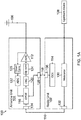
- FIG 1A is a high level block diagram of one embodiment of an exemplary radio system 100.
- Radio system 100 includes a radio unit 102 and an antenna unit 104. It is to be understood that the radio system 100 can include other component not shown and that Figure 1 has been simplified for purposes of explanation. Similarly, each of the radio unit 102 and the antenna unit 104 may include additional components, as understood by one of skill in the art, and that depiction of the radio unit 102 and antenna unit 104 has been simplified for purposes of explanation.
- the radio unit 102 is located physically separate from the antenna unit 104.
- the antenna unit 104 can be co-located or located near an antenna 106 configured to radiate radio frequency (RF) signals.
- the radio unit 102 can be located, for example,inside the avionics bay of an aircraft.
- the radio unit 102 is located in an avionics bay in the nose of the aircraft 200 and the antenna unit 104 is located near a tail of the aircraft 200 near a corresponding antenna.
- the radio unit 102 is waveform/platformindependent and is configured to process signals from an upstream device 108 for transmission as an RF signal via the antenna 106.
- the upstream device 108 can be implemented as any device for providing data to be transmitted.
- the upstream device 108 can be implemented as, but is not limited to, adata link Communications Management Unit (CMU) or an audio communications system.
- CMU Communications Management Unit
- the radio unit 102 and the antenna unit 104 can be implemented as different types of radios, such as communications, navigation, and surveillance radios.
- the radio system 100 can be implemented as, but not limited to, a satellite communications (SATCOM) radio, an ultra-high frequency (UHF) radio, or a very high frequency (VHF) radio.
- the radio unit 102 includes a modulator 130 configured to modulate the signals provided by the upstream device using techniques known to one of skill in the art.
- the modulated signals are then provided to the antenna unit 104 via port or interface 132.
- the interface 132 is coupled to a corresponding interface 134 in the antenna unit 104 by a physical medium 110 between the antenna unit 104 and the radio unit 102.
- the physical medium 110 can be implemented as any appropriate media for carrying data signals, such as, but not limited to, coaxial cable, twisted pair copper wire, or fiber optic cable.
- the antenna unit 104 is configured to amplify the power of the modulated signal received from the radio unit 102 via a high power amplifier 112. The amplified signal is then output to the antenna 106 from which the amplified signal is radiated.
- high power amplifiersoften have non-linear components in the amplifier transfer function which causes distortions in the amplified signal. These distortions modify the desired signal or add frequencies other than the intended frequency of the radiated signal.
- the non-linearity in the amplifier transfer function typically increases as the output of the high power amplifier 112 approaches the saturation level or maximum output of the high power amplifier
- Conventional systems often use larger power amplifiers that are operated at a lower level to reduce the effects of non-linearity.
- the use of larger power amplifiers in this conventional manner is inefficient. In such conventional power amplifiers, a lot of current is drawn from the power supply line and a lot of unwanted heat is dissipated into the environment around the antenna unit 104.
- these conventional power amplifiers are heavy because of a large heat sink to dissipate high thermal power.
- the System 100 pre-distorts the signal from the radio unit 102 prior to passing the signal through the high power amplifier 112.
- the signal is pre-distorted in a manner opposite to the distortion introduced by the high power amplifier 112 such that the pre-distortion approximately cancels out the distortion created by the high power amplifier 112.
- the pre-distortion function is split between the radio unit 102 and the antenna unit 104.
- the radio unit 102 includes a coefficient computation engine (CCE) 114 and the antenna unit 104 includes a digital pre-distortion engine (DPDE) 116.
- CCE coefficient computation engine
- DPDE digital pre-distortion engine
- the coefficient computation engine 114 calculates coefficients for use by the digital pre-distortion engine 116.
- the digital pre-distortion engine 116 applies a mathematical function, such as a polynomial function, to the modulated digital data signal received from the radio unit 102.
- the coefficients of the mathematical function are computed in the coefficient computation engine 114 of radio unit 102.
- the pre-distorted digital signal output from the digital pre-distortion engine 116 is then converted to an analog signal in the Digital to Analog Converter(DAC) 120 and up-converted from a baseband or an intermediate frequency to a radio frequency in Up converter 124.
- the analog RF signal is then amplified in the high power amplifier 112.
- the amplified RF signal is then radiated via the antenna 106.
- a feedback loop from the output of the high power amplifier 112 is provided back to the digital pre-distortion engine 116.
- the feedback signal from the output of the high power amplifier 112 is down converted to a baseband or an intermediate frequency in the down converter 126 and then converted to a digital signal in the Analog to Digital Converter (ADC) 122.
- ADC Analog to Digital Converter
- the digital pre-distortion engine 116 calculates feedback data that is used by the coefficient computation engine 114 to update or calculate new coefficients.
- the feedback data is an error signal which represents a difference between the digital downconverted feedback signal and the modulated data signal input into the digital pre-distortion engine 116.
- the error signal represents the difference between the output of the DPDE 116 and a post-distorted version of the feedback signal.
- the feedback data includes samples from the output of the DPDE 116 and samples from the feedback signal from the output of the power amplifier 112.
- the number of samples from the feedback signal is greater than the number of samples from the output of the DPDE 116.
- the number of samples from the output of DPDE 116 can be 400 while the number of samples from the feedback signal is 1000 in one embodiment.
- the CCE 114 Having more samples from the feedback signal enables the CCE 114 to determine the delay through the up-converter 124, power amplifier 112, and down-converter 126 and "align" the samples from the DPDE 116 with the corresponding block of samples from the feedback signal.
- the periodicity of providing the samples to the CCE 114 determines how often the pre-distortion coefficients are re-calculated.
- the blocks of data samples do not have to include 100% of the DPDE 116 output or power amplifier 112 output so the amount of data fed back to the CCE 114 is lower than a feedback signal of a continuous stream of error signal samples.
- the digital pre-distortion engine 116 outputs the error signal to the coefficient computation engine 114 via an interface 128, in this embodiment.
- the interface 128 is coupled to a corresponding interface 136 in the radio unit 102 by a physical medium 118.
- Physical medium 118 can be implemented using coaxial cable, fiber optic cable, twisted pair copper wire, etc.
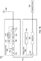
- a separate medium 118 and corresponding interfaces 128/136 are used in this embodiment, it is to be understood that, in other embodiments, the error signal is provided to the radio unit over the physical medium 110 and corresponding interfaces 134/132, as shown for example in Figure IB.
- the coefficient computation engine 114 calculates new/updated coefficients.
- the new coefficients are then output from coefficient computation engine 114 back to the digital pre-distortion engine 116 via the physical medium 118, in this example.
- the updated coefficients are output from the CCE 114 to the DPDE 116 via the physical medium 110.
- the new coefficients are then used by the digital pre-distortion engine 116 in the mathematical equation to pre-distort the input data signal.
- the feedback loop enables adjustment of the pre-distortion to improve the correspondence between the digital pre-distortion and the distortion from the high power amplifier 112 such that the pre-distortion effectively cancels out the distortion from the high power amplifier 112.
- the pre-distortion can be adjusted to compensate for such changes.
- the coefficients do not have to be calculated in real time. Rather, an appropriate period can be pre-determined for calculating the coefficients depending on the application. For example, the period can be, but is not limited to, once per second, once per minute, once per hour, etc.
- the embodiments described herein enable benefits not achieved by implementing the pre-distortion function in a single device.
- the pre-distortion function is split to utilize more efficiently the respective hardware in the radio unit 102 and antenna unit 104.
- application of the mathematical operation to pre-distort the data signal should be performed quickly in order to reduce latency between the input of the data signal and the output of the pre-distorted data signal.
- the processing time for applying the pre-distortion mathematical operation approaches real time, the less latency is introduced by the pre-distortion.
- the type of operation or algorithm used to apply the pre-distortion is typically different from the type of operation to compute the coefficients for the pre-distortion mathematical operation.
- the pre-distortion mathematical operation typically involves relatively simple linear operations, such as multiply and accumulate operations.
- the computation of the coefficients often involves more complex operations, such as performing Fast Fourier Transforms if the processing is in the frequency domain, for example, or solving coupled linear equations that require pseudo matrix inversions if the processing is in the time domain.
- the ability to perform both real time operations and non-linear computations places relatively stringent requirements on the processing components if implemented in the same device. However, through the embodiments described herein, the requirements on the processing components can be relaxed.
- the algorithms for computing the coefficients require processing with higher precision than the algorithms for applying the pre-distortion.
- the algorithms for computing the coefficients are often implemented better using floating point processing than fixed point processing, but the coefficients do not need to becomputed in real time.
- the algorithms for applying the pre-distortion should be performed in real time, but they can be implemented using fixed point precision logic.
- the pre-distortion function is divided between a digital pre-distortion engine 116 in the antenna unit 104 and a coefficient computation engine 114 in the radio unit 102.
- the DPDE 116 can be implemented using components suited for real time processing whereas the CCE 114 can be implemented using components suited for more complex computations.
- the DPDE 116 can be implemented, in some embodiments, using a field programmable gate array (FPGA) while the CCE 114 is implemented using a digital signal processor (DSP) or general purpose processor executing instructions stored on a computer readable medium.
- FPGA field programmable gate array
- DSP digital signal processor
- the DPDE 116 Since the DPDE 116 does not need to perform the more complex calculations used in calculating coefficients the DPDE 116 can be implemented using faster and more efficient fixed-point processing equipment for pre-distorting the data signal in near real time or real time as opposed to both pre-distorting the signal in real time and calculating the coefficients with the same processing components. Likewise, since the CCE 114 does not need to calculate the coefficients in real time, the CCE 114 can be implemented using slower and less expensive floating point processing equipment for computing the coefficients as opposed to both pre-distorting the data signal in real time and calculating the coefficients with the same processing components. In addition, splitting the pre-distortion function into two separate device (i.e. the DPDE 116 in the antenna unit 104 and the CCE 114 in the radio unit 102) aids in meeting other requirements, such as cooling requirements, in the antenna unit 104 by reducing the amount of hardware and processing in the antenna unit 104.
- the feedback signal discussed above would have to be provided from the antenna unit 104, which amplifies the analog RF signal, to the radio unit 102, which is located remote from the antenna unit 104.
- the term "remote” means located separate or at a distance from the other unit. In other words, the antenna unit 104 and the radio unit 102 are not co-located or located next to one another in the same area.
- Providing the feedback signal to the radio unit 102 would require a separate interface between the antenna unit 104 and radio unit 102 which can accommodate a sufficiently high data rate to provide the raw samples of the feedback signal. For example, sending the raw data samples in the feedback signal can involve tens or hundreds of megabits per second.
- splitting the digital pre-distortion function as described above to place the digital pre-distortion engine 116 in the antenna unit 104 eliminates the need to provide the feedback signal to the radio unit 102. Instead, the DPDE 116 provides the error signal to the CCE 114 and the CCE 114 provides the updated coefficients to the DPDE 116.
- the transfer of this data between the DPDE 116 and CCE 114 involves a lower data rate, such as kilobits or hundreds of bits per second, which is easier to implement than an interface to support tens or hundreds of megabits per second.
- a lower data rate such as kilobits or hundreds of bits per second
- providing the feedback signal to the radio unit 102 would require a separate coaxial cable or a frequency diplexing unit which adds additional weight.
- the lower bandwidth required for the error signal and coefficients can be met with smaller or lighter cables and components, due to the lower bandwidth requirements.
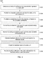
- Figure 3 is a flow chart depicting one embodiment of an exemplary method 300 of compensating for distortion introduced by a power amplifier.
- Method 300 can be implemented in the radio system 100 described above.
- a plurality of coefficients for a pre-distortion operation is computed in a radio unit.
- the coefficients are computed in the radio unit such that pre-distortion applied to a digital data signal is approximately equal and opposite to distortion introduced by the power amplifier. In this way, the pre-distortion approximately cancels the distortion introduced by the power amplifier.
- the distortion introduced by power amplifier can be estimated through measuring the output of the power amplifier, measuring the error vector magnitude (EVM), or through empirical study of the power amplifier, for example.
- EVM error vector magnitude
- the computed coefficients are output or provided from the radio unit to an antenna unit located remote from the radio unit, as described above.
- the antenna unit is physically separate from the radio unit and can be located, for example, near an antenna whereas the radio unit can be located in an avionics bay of an aircraft.
- a digital data signal is pre-distorted in the antenna unit based on the computed coefficients received from the radio unit.
- the digital data signal is also modulated or encoded in the radio unit and provided to the antenna unit for amplification.
- the pre-distorted data signal is converted to a pre-distorted analog data signal in a digital to analog converter.
- the analog pre-distorted data signal can also up converted from a baseband or intermediate frequency to a radio frequency prior to amplification, in some embodiments, as described above.
- the analog pre-distorted signal is amplified by the power amplifier in the antenna unit.
- Amplifying the analog pre-distorted data signal introduces distortion into the amplified analog pre-distorted data signal.
- the distortion introduced by the power amplifier is approximately cancelled by the pre-distortion such that the output signal closely matches the input signal.
- feedback data is calculated in the antenna unit based on a feedback signal containing samples of the output of the power amplifier.
- the analog output of the power amplifier is down converted and converted to a digital signal, as described above.
- the digital feedback signal can then be compared to the digital data signal from the radio unit to determine a difference or error between the two digital signals.
- other feedback data is computed based on the feedback signal, as discussed above.
- the feedback data is output to the radio unit.
- the feedback data can be output over the same interface over which the digital data signal is communicated to the antenna unit or over a separate interface, as described above.
- the radio unit re-calculates the coefficients based on the feedback data at a specified period and provides the recalculated coefficients to the antenna unit.
- the radio unit can be configured to recalculate the coefficients once a second, once a minute, or once an hour, etc. In this way, changes in the power amplifier performance are compensated for, such as changes due to temperature or environmental changes.
- Example 1 includes a radio system comprising: a radio unit comprising a modulator configured to modulate a digital data signal and a signal interface; an antenna unit comprising a signal interface, the antenna unit being physically separate from the radio unit and located remote from the radio unit; and a cable coupling the signal interface of the radio unit to the signal interface of the antenna unit; wherein the antenna unit further comprises: a digital pre-distortion engine configured to receive the modulated digital data signal and to pre-distort the modulated digital data signal; a digital to analog converter configured to convert the pre-distorted digital data signal to a pre-distorted analog data signal; and a power amplifier configured to amplify the pre-distorted analog data signal, wherein the power amplifier distorts the pre-distorted analog data signal, the distortion introduced by the power amplifier being opposite to the pre-distortion introduced by the digital pre-distortion engine such that the pre-distortion introduced by the digital pre-distortion engine approximately cancels the distortion introduced by the power amplifier; wherein the radio unit further
Landscapes
- Engineering & Computer Science (AREA)
- Power Engineering (AREA)
- Physics & Mathematics (AREA)
- Computer Networks & Wireless Communication (AREA)
- Signal Processing (AREA)
- Nonlinear Science (AREA)
- General Physics & Mathematics (AREA)
- Aviation & Aerospace Engineering (AREA)
- Microelectronics & Electronic Packaging (AREA)
- Astronomy & Astrophysics (AREA)
- Algebra (AREA)
- Mathematical Analysis (AREA)
- Mathematical Optimization (AREA)
- Pure & Applied Mathematics (AREA)
- Amplifiers (AREA)
Claims (8)
- Système radio (100) comprenant :une unité radio (102) comprenant un modulateur (130) configuré pour moduler un signal de données numérique et une interface de signaux (132) ;une unité d'antenne (104) comprenant une interface de signaux (134), l'unité d'antenne étant physiquement séparée de l'unité radio et située à distance de l'unité radio ; etun câble (110) couplant l'interface de signaux de l'unité radio à l'interface de signaux de l'unité d'antenne ;dans lequel l'unité d'antenne comprend en outre :un moteur de prédistorsion numérique (116) configuré pour recevoir le signal de données numérique modulé et prédéformer le signal de données numérique modulé ;un convertisseur numérique/analogique (120) configuré pour convertir le signal de données numérique prédéformé en un signal de données analogique prédéformé ; etun amplificateur de puissance (112) configuré pour amplifier le signal de données analogique prédéformé, l'amplificateur de puissance déformant le signal de données analogique prédéformé, la distorsion introduite par l'amplificateur de puissance étant opposée à la prédistorsion introduite par le moteur de prédistorsion numérique de telle sorte que la prédistorsion introduite par le moteur de prédistorsion numérique annule la distorsion introduite par l'amplificateur de puissance ;dans lequel l'unité radio comprend en outre un moteur de calcul de coefficients (114) configuré pour calculer des coefficients utilisés par le moteur de prédistorsion numérique pour prédéformer le signal de données numérique modulé ;dans lequel le moteur de prédistorsion numérique (116) est configuré pour recevoir un signal de rétroaction et l'unité d'antenne comprend en outre une boucle de rétroaction comprenant un convertisseur abaisseur et un convertisseur A/N et dans lequel la sortie de l'amplificateur de puissance est connectée à l'entrée du convertisseur abaisseur et la sortie du convertisseur A/N est connectée au moteur de prédistorsion numérique, la sortie du convertisseur A/N ayant une cadence d'échantillonnagedans lequel le moteur de prédistorsion numérique (116) est configuré pour calculer des données de rétroaction en fonction du signal de rétroaction et produire en sortie les données de rétroaction à destination du moteur de calcul de coefficients (114) dans l'unité radio (102) en vue de leur utilisation dans le recalcul des coefficients, dans lequel le débit de données des données de rétroaction est inférieur à la cadence d'échantillonnage.
- Système radio (10) selon la revendication 1, comprenant en outre un dispositif amont (108) couplé à l'unité radio (102), le dispositif amont étant configuré pour fournir le signal de données numériques à l'unité radio.
- Système radio (100) selon la revendication 1, dans lequel le moteur de calcul de coefficients (114) est configuré pour recalculer les coefficients en fonction des données de rétroaction reçues à une période spécifiée de telle sorte que les coefficients ne soient pas recalculés en temps réel.
- Système radio (100) selon la revendication 1, dans lequel l'unité radio (102) est située dans une baie avionique et l'unité d'antenne (104) est située près d'une antenne distante de la baie avionique.
- Système radio (100) selon la revendication 1, dans lequel l'unité d'antenne (104) et l'unité radio (102) comprennent ensemble un d'une radio satellite, d'une radio à très haute fréquence (VHF), ou d'une radio à ultra haute fréquence (UHF).
- Système radio (100) selon la revendication 1, dans lequel l'amplificateur de puissance (112) est exploité près du niveau de saturation de l'amplificateur de puissance.
- Procédé (300) de compensation de la distorsion introduite par un amplificateur de puissance, le procédé comprenant :le calcul d'une pluralité de coefficients pour une opération de prédistorsion dans une unité radio (302) ;la fourniture des coefficients calculés par l'unité radio à une unité d'antenne, l'unité d'antenne étant physiquement séparée de l'unité radio et située à distance de l'unité radio (304) ;la prédistorsion d'un signal de données numérique dans l'unité d'antenne en fonction des coefficients calculés reçus depuis l'unité radio, le signal de données numérique étant reçu dans l'unité d'antenne depuis l'unité radio (306) ;la conversion du signal de données numérique modulé dans l'unité d'antenne en un signal de données analogique prédéformé (308) ; etl'amplification du signal de données analogique prédéformé avec l'amplificateur de puissance dans l'unité d'antenne, dans lequel l'amplification du signal de données analogique prédéformé introduit une distorsion dans le signal de donnés prédéformé analogique amplifié (310) ;dans lequel les coefficients utilisés dans l'application de la prédistorsion sont calculés dans l'unité radio de telle sorte que la prédistorsion soit égale et opposée à la distorsion introduite par l'amplificateur de puissance de telle sorte que la prédistorsion annule la distorsion introduite par l'amplificateur de puissance ;le calcul de données de rétroaction dans l'unité d'antenne en fonction d'un signal de rétroaction, l'unité d'antenne comprenant en outre une boucle de rétroaction comprenant un convertisseur abaisseur et un convertisseur A/N et la sortie de l'amplificateur de puissance étant connectée à l'entrée du convertisseur abaisseur et la sortie du convertisseur A/N étant connectée au moteur de prédistorsion numérique, la sortie du convertisseur A/N ayant une cadence d'échantillonnage, dans lequel le débit de données des données de rétroaction est inférieur à la cadence d'échantillonnage ; etla production en sortie des données de rétroaction à destination de l'unité radio en vue de leur utilisation dans le recalcul des coefficients dans l'unité radio (314) .
- Procédé (300) selon la revendication 7, comprenant en outre le recalcul des coefficients dans l'unité radio en fonction des données de rétroaction reçues à une période spécifiée de telle sorte que les coefficients ne soit pas recalculés en temps réel (316).
Applications Claiming Priority (1)
| Application Number | Priority Date | Filing Date | Title |
|---|---|---|---|
| US14/488,026 US9379744B2 (en) | 2014-09-16 | 2014-09-16 | System and method for digital predistortion |
Publications (2)
| Publication Number | Publication Date |
|---|---|
| EP2999115A1 EP2999115A1 (fr) | 2016-03-23 |
| EP2999115B1 true EP2999115B1 (fr) | 2019-11-06 |
Family
ID=54147073
Family Applications (1)
| Application Number | Title | Priority Date | Filing Date |
|---|---|---|---|
| EP15185373.6A Active EP2999115B1 (fr) | 2014-09-16 | 2015-09-15 | Système et procédé de prédistorsion numérique |
Country Status (4)
| Country | Link |
|---|---|
| US (1) | US9379744B2 (fr) |
| EP (1) | EP2999115B1 (fr) |
| CN (1) | CN105429602B (fr) |
| CA (1) | CA2903606A1 (fr) |
Families Citing this family (7)
| Publication number | Priority date | Publication date | Assignee | Title |
|---|---|---|---|---|
| WO2016003343A1 (fr) * | 2014-07-04 | 2016-01-07 | Telefonaktiebolaget L M Ericsson (Publ) | Tête radio à distance et procédé associé |
| US10797750B2 (en) * | 2016-02-24 | 2020-10-06 | Cisco Technology, Inc. | System architecture for supporting digital pre-distortion and full duplex in cable network environments |
| EP3288182B1 (fr) * | 2016-08-25 | 2020-07-01 | Cisco Technology, Inc. | Architecture de système permettant de prendre en charge la pré-distorsion numérique et le duplex intégral dans des environnements de réseau câblé |
| DE102018220089A1 (de) * | 2018-11-22 | 2020-05-28 | Infineon Technologies Ag | Digitale Vorverzerrungstechnik für eine Schaltungsanordnung mit einem Leistungsverstärker |
| CN111082756B (zh) * | 2019-12-11 | 2023-06-06 | 电子科技大学 | 一种用于mimo发射机的数模混合预失真结构 |
| JP7393741B2 (ja) * | 2020-03-30 | 2023-12-07 | 住友電気工業株式会社 | 歪補償装置、歪補償方法、コンピュータプログラム、及び通信装置 |
| CN113468842A (zh) * | 2021-08-16 | 2021-10-01 | 重庆大学 | 一种基于矢量量化的宽带数字预失真算法 |
Family Cites Families (50)
| Publication number | Priority date | Publication date | Assignee | Title |
|---|---|---|---|---|
| US6104926A (en) | 1995-07-31 | 2000-08-15 | Gte Airfone, Incorporated | Call handoff |
| US5870668A (en) | 1995-08-18 | 1999-02-09 | Fujitsu Limited | Amplifier having distortion compensation and base station for radio communication using the same |
| US5903823A (en) | 1995-09-19 | 1999-05-11 | Fujitsu Limited | Radio apparatus with distortion compensating function |
| BR9816112A (pt) | 1998-12-24 | 2001-09-04 | Nokia Networks Oy | Transmissor de portador de múltiplas frequências, estação base, e, método de transmissão de frequência de múltiplos portadores |
| US6798843B1 (en) * | 1999-07-13 | 2004-09-28 | Pmc-Sierra, Inc. | Wideband digital predistortion linearizer for nonlinear amplifiers |
| JP4183364B2 (ja) * | 1999-12-28 | 2008-11-19 | 富士通株式会社 | 歪補償装置 |
| JP3805221B2 (ja) | 2001-09-18 | 2006-08-02 | 株式会社日立国際電気 | 歪み補償装置 |
| US6720829B2 (en) | 2001-12-25 | 2004-04-13 | Matsushita Electric Industrial Co., Ltd. | Distortion-compensated amplifying circuit |
| US6985704B2 (en) * | 2002-05-01 | 2006-01-10 | Dali Yang | System and method for digital memorized predistortion for wireless communication |
| EP1367711A1 (fr) | 2002-05-30 | 2003-12-03 | Motorola, Inc. | Amplificateur de puissance avec dispositif de prédistorsion |
| KR100448892B1 (ko) | 2002-06-04 | 2004-09-18 | 한국전자통신연구원 | 고전력 증폭기의 비선형 왜곡 보상을 위한 전치 왜곡 장치및 그 방법 |
| US20040022210A1 (en) * | 2002-08-01 | 2004-02-05 | Frank Edward H. | Cooperative transceiving between wireless interface devices of a host device |
| JP4033794B2 (ja) * | 2003-03-24 | 2008-01-16 | 株式会社エヌ・ティ・ティ・ドコモ | 高効率線形電力増幅器 |
| SE525221C2 (sv) | 2003-03-25 | 2004-12-28 | Ericsson Telefon Ab L M | Förförvrängare för effektförstärkare |
| WO2004112240A1 (fr) | 2003-06-18 | 2004-12-23 | Telefonaktiebolaget Lm Ericsson (Publ) | Distorsion prealable d'amplificateur de puissance |
| US7149257B2 (en) | 2003-07-03 | 2006-12-12 | Powerwave Technologies, Inc. | Digital predistortion system and method for correcting memory effects within an RF power amplifier |
| JP4255361B2 (ja) | 2003-11-07 | 2009-04-15 | 富士通株式会社 | 歪み補償増幅器 |
| US7170344B2 (en) | 2004-02-03 | 2007-01-30 | Ntt Docomo, Inc. | Multi-band predistorter using power series representation |
| JP4505238B2 (ja) | 2004-02-25 | 2010-07-21 | 株式会社日立国際電気 | 歪補償回路 |
| US20050215249A1 (en) | 2004-03-12 | 2005-09-29 | Arinc Incorporated | Systems and methods for wireless communications onboard aircraft |
| US20050212708A1 (en) * | 2004-03-26 | 2005-09-29 | Broadcom Corporation | Antenna configuration for wireless communication device |
| ATE487272T1 (de) | 2004-05-19 | 2010-11-15 | Ericsson Telefon Ab L M | Adaptives vorverzerrungsverfahren und anordnung |
| US7113037B2 (en) | 2004-07-14 | 2006-09-26 | Raytheon Company | Performing remote power amplifier linearization |
| US7493152B1 (en) * | 2004-12-01 | 2009-02-17 | Broadcom Corporation | Integrated circuit incorporating antennas |
| JP4896424B2 (ja) | 2005-04-22 | 2012-03-14 | 株式会社日立国際電気 | 歪補償増幅器 |
| DE602005020372D1 (de) | 2005-09-28 | 2010-05-12 | Fujitsu Ltd | Verzerrungskompensationseinrichtung |
| US7772925B2 (en) | 2006-03-31 | 2010-08-10 | Freescale Semiconductor, Inc. | Power amplifier with pre-distorter |
| US7831255B1 (en) | 2006-07-31 | 2010-11-09 | Rockwell Collins, Inc. | System and method of providing automated availability and integrity verification for aviation software defined radios |
| US8294516B2 (en) | 2007-06-15 | 2012-10-23 | Broadcom Corporation | Power amplifier pre-distortion |
| FI20075690A0 (fi) | 2007-10-01 | 2007-10-01 | Nokia Corp | Signaalin esivääristäminen radiolähettimessä |
| US7929927B2 (en) | 2007-10-29 | 2011-04-19 | Freescale Semiconductor, Inc. | Adaptive pre-distortion with interference detection and mitigation |
| KR101669173B1 (ko) | 2007-12-07 | 2016-10-25 | 달리 시스템즈 씨오. 엘티디. | 베이스밴드-도출형 광대역 rf 디지털 전치 왜곡 시스템 |
| JP5136143B2 (ja) | 2008-03-21 | 2013-02-06 | 富士通株式会社 | Ofdm信号送信装置 |
| WO2010001357A1 (fr) | 2008-07-02 | 2010-01-07 | Innovaradio S.A. | Procédé de prédistorsion et dispositif pour améliorer la puissance électrique d'amplificateurs de puissance dans des applications de communication numérique sans fil |
| US8412132B2 (en) | 2008-08-21 | 2013-04-02 | Freescale Semiconductor, Inc. | Techniques for adaptive predistortion direct current offset correction in a transmitter |
| US8706062B1 (en) | 2008-12-19 | 2014-04-22 | Scintera Networks, Inc. | Self-adaptive power amplification |
| CN101478514B (zh) * | 2009-01-08 | 2011-08-24 | 福建邮科通信技术有限公司 | 一种实现数字功率预失真的方法 |
| JP5338378B2 (ja) | 2009-03-02 | 2013-11-13 | 富士通株式会社 | 歪補償装置及び方法 |
| US8498591B1 (en) * | 2009-08-21 | 2013-07-30 | Marvell International Ltd. | Digital Predistortion for nonlinear RF power amplifiers |
| CN102082752B (zh) * | 2010-02-25 | 2014-03-19 | 电信科学技术研究院 | 一种数字预失真处理方法及设备 |
| EP2403314A1 (fr) | 2010-06-29 | 2012-01-04 | Alcatel Lucent | Dispositif de tête radio et son procédé de fonctionnement |
| JP5459158B2 (ja) | 2010-09-21 | 2014-04-02 | 富士通株式会社 | 送信装置及び歪補償方法 |
| US20120195392A1 (en) | 2011-02-02 | 2012-08-02 | Provigent Ltd. | Predistortion in split-mount wireless communication systems |
| JP6207806B2 (ja) | 2011-05-10 | 2017-10-04 | 富士通株式会社 | 歪補償装置及び歪補償方法 |
| US8711976B2 (en) | 2011-05-12 | 2014-04-29 | Andrew Llc | Pre-distortion architecture for compensating non-linear effects |
| US20120328050A1 (en) | 2011-06-21 | 2012-12-27 | Telefonaktiebolaget L M Ericsson (Publ) | Centralized adaptor architecture for power amplifier linearizations in advanced wireless communication systems |
| US8391809B1 (en) | 2011-10-13 | 2013-03-05 | Futurewei Technologies, Inc. | System and method for multi-band predistortion |
| US8606197B2 (en) | 2012-01-16 | 2013-12-10 | Telefonaktiebolaget L M Ericsson (Publ) | Method and system for generating odd order predistortions for a power amplifier receiving concurrent dual band inputs |
| JP5861521B2 (ja) * | 2012-03-19 | 2016-02-16 | 富士通株式会社 | 送信装置及びルックアップテーブルの更新方法 |
| US9001928B2 (en) * | 2013-03-28 | 2015-04-07 | Texas Instruments Incorporated | Transmitter first/second digital predistortion and first/second adaption circuitry with feedback |
-
2014
- 2014-09-16 US US14/488,026 patent/US9379744B2/en active Active
-
2015
- 2015-09-08 CA CA2903606A patent/CA2903606A1/fr not_active Abandoned
- 2015-09-15 EP EP15185373.6A patent/EP2999115B1/fr active Active
- 2015-09-15 CN CN201510683571.4A patent/CN105429602B/zh active Active
Non-Patent Citations (1)
| Title |
|---|
| None * |
Also Published As
| Publication number | Publication date |
|---|---|
| CN105429602B (zh) | 2021-02-02 |
| EP2999115A1 (fr) | 2016-03-23 |
| CN105429602A (zh) | 2016-03-23 |
| US9379744B2 (en) | 2016-06-28 |
| CA2903606A1 (fr) | 2016-03-16 |
| US20160080009A1 (en) | 2016-03-17 |
Similar Documents
| Publication | Publication Date | Title |
|---|---|---|
| EP2999115B1 (fr) | Système et procédé de prédistorsion numérique | |
| US8428525B2 (en) | Predistorter for a multi-antenna transmitter | |
| KR101789924B1 (ko) | 적응형 디지털 전치 왜곡을 위한 디바이스 및 방법 | |
| EP3381129A1 (fr) | Linéarisation de réseau d'antennes actives | |
| CN110326214A (zh) | 失真补偿装置和失真补偿方法 | |
| US9735814B1 (en) | High power efficient amplification at cable modems through digital pre-distortion and machine learning in cable network environments | |
| KR101386239B1 (ko) | 비선형 왜곡의 보상을 위한 전치 왜곡 장치 및 방법 | |
| US20130271212A1 (en) | Digital Predistorter (DPD) Structure Based On Dynamic Deviation Reduction (DDR)-Based Volterra Series | |
| US8655289B2 (en) | Distortion compensation device, transmitter, and distortion compensation method | |
| CN101902418B (zh) | 失真补偿装置和方法 | |
| US12250013B2 (en) | System and method for digital predistortion | |
| US9712193B1 (en) | High power efficient amplifier through digital pre-distortion and machine learning in cable network environments | |
| KR102863361B1 (ko) | 전력 증폭기의 전하 트래핑 효과들을 위해 전송 신호를 보상하는 시스템들 및 방법들 | |
| Plotnikov et al. | Joint compensation of power amplifier nonlinear distortions on transmitter and receiver sides | |
| KR101470817B1 (ko) | 복수의 비선형 증폭기에 대하여 단일 피드백 회로를 사용하는 전치보상 장치 및 방법 | |
| US9473334B2 (en) | Wireless transmission device | |
| KR101712752B1 (ko) | 전치왜곡 아날로그 빔 포밍 시스템 및 전치왜곡 방법 | |
| Watanabe et al. | High speed downlink system for small satellite and high-efficiency x-band GaN SSPA | |
| US9584168B2 (en) | Distortion compensator and distortion compensation method | |
| KR101892369B1 (ko) | 고출력 전자기파 송신 방법 및 장치 | |
| Han et al. | Computationally efficient look-up-tables for behavioral modelling and digital pre-distortion of multi-standard wireless systems | |
| US9236893B2 (en) | Distortion compensation device and distortion compensation method | |
| KR101818834B1 (ko) | 광 무선 통신 시스템의 등화기 및 상기 등화기 제어 방법 | |
| Zhu et al. | Theoretical and experimental studies of a probabilistic-based memoryless PA linearization technique | |
| KR20140077742A (ko) | 전력 증폭기의 선형성 개선을 위한 디지털 전치 왜곡 장치 |
Legal Events
| Date | Code | Title | Description |
|---|---|---|---|
| PUAI | Public reference made under article 153(3) epc to a published international application that has entered the european phase |
Free format text: ORIGINAL CODE: 0009012 |
|
| 17P | Request for examination filed |
Effective date: 20150915 |
|
| AK | Designated contracting states |
Kind code of ref document: A1 Designated state(s): AL AT BE BG CH CY CZ DE DK EE ES FI FR GB GR HR HU IE IS IT LI LT LU LV MC MK MT NL NO PL PT RO RS SE SI SK SM TR |
|
| AX | Request for extension of the european patent |
Extension state: BA ME |
|
| STAA | Information on the status of an ep patent application or granted ep patent |
Free format text: STATUS: EXAMINATION IS IN PROGRESS |
|
| 17Q | First examination report despatched |
Effective date: 20170320 |
|
| GRAP | Despatch of communication of intention to grant a patent |
Free format text: ORIGINAL CODE: EPIDOSNIGR1 |
|
| STAA | Information on the status of an ep patent application or granted ep patent |
Free format text: STATUS: GRANT OF PATENT IS INTENDED |
|
| INTG | Intention to grant announced |
Effective date: 20190604 |
|
| GRAS | Grant fee paid |
Free format text: ORIGINAL CODE: EPIDOSNIGR3 |
|
| GRAA | (expected) grant |
Free format text: ORIGINAL CODE: 0009210 |
|
| STAA | Information on the status of an ep patent application or granted ep patent |
Free format text: STATUS: THE PATENT HAS BEEN GRANTED |
|
| AK | Designated contracting states |
Kind code of ref document: B1 Designated state(s): AL AT BE BG CH CY CZ DE DK EE ES FI FR GB GR HR HU IE IS IT LI LT LU LV MC MK MT NL NO PL PT RO RS SE SI SK SM TR |
|
| REG | Reference to a national code |
Ref country code: GB Ref legal event code: FG4D |
|
| REG | Reference to a national code |
Ref country code: CH Ref legal event code: EP Ref country code: AT Ref legal event code: REF Ref document number: 1200172 Country of ref document: AT Kind code of ref document: T Effective date: 20191115 |
|
| REG | Reference to a national code |
Ref country code: DE Ref legal event code: R096 Ref document number: 602015041016 Country of ref document: DE |
|
| REG | Reference to a national code |
Ref country code: IE Ref legal event code: FG4D |
|
| REG | Reference to a national code |
Ref country code: NL Ref legal event code: MP Effective date: 20191106 |
|
| REG | Reference to a national code |
Ref country code: LT Ref legal event code: MG4D |
|
| PG25 | Lapsed in a contracting state [announced via postgrant information from national office to epo] |
Ref country code: LT Free format text: LAPSE BECAUSE OF FAILURE TO SUBMIT A TRANSLATION OF THE DESCRIPTION OR TO PAY THE FEE WITHIN THE PRESCRIBED TIME-LIMIT Effective date: 20191106 Ref country code: PL Free format text: LAPSE BECAUSE OF FAILURE TO SUBMIT A TRANSLATION OF THE DESCRIPTION OR TO PAY THE FEE WITHIN THE PRESCRIBED TIME-LIMIT Effective date: 20191106 Ref country code: NO Free format text: LAPSE BECAUSE OF FAILURE TO SUBMIT A TRANSLATION OF THE DESCRIPTION OR TO PAY THE FEE WITHIN THE PRESCRIBED TIME-LIMIT Effective date: 20200206 Ref country code: NL Free format text: LAPSE BECAUSE OF FAILURE TO SUBMIT A TRANSLATION OF THE DESCRIPTION OR TO PAY THE FEE WITHIN THE PRESCRIBED TIME-LIMIT Effective date: 20191106 Ref country code: LV Free format text: LAPSE BECAUSE OF FAILURE TO SUBMIT A TRANSLATION OF THE DESCRIPTION OR TO PAY THE FEE WITHIN THE PRESCRIBED TIME-LIMIT Effective date: 20191106 Ref country code: SE Free format text: LAPSE BECAUSE OF FAILURE TO SUBMIT A TRANSLATION OF THE DESCRIPTION OR TO PAY THE FEE WITHIN THE PRESCRIBED TIME-LIMIT Effective date: 20191106 Ref country code: FI Free format text: LAPSE BECAUSE OF FAILURE TO SUBMIT A TRANSLATION OF THE DESCRIPTION OR TO PAY THE FEE WITHIN THE PRESCRIBED TIME-LIMIT Effective date: 20191106 Ref country code: BG Free format text: LAPSE BECAUSE OF FAILURE TO SUBMIT A TRANSLATION OF THE DESCRIPTION OR TO PAY THE FEE WITHIN THE PRESCRIBED TIME-LIMIT Effective date: 20200206 Ref country code: PT Free format text: LAPSE BECAUSE OF FAILURE TO SUBMIT A TRANSLATION OF THE DESCRIPTION OR TO PAY THE FEE WITHIN THE PRESCRIBED TIME-LIMIT Effective date: 20200306 Ref country code: GR Free format text: LAPSE BECAUSE OF FAILURE TO SUBMIT A TRANSLATION OF THE DESCRIPTION OR TO PAY THE FEE WITHIN THE PRESCRIBED TIME-LIMIT Effective date: 20200207 |
|
| PG25 | Lapsed in a contracting state [announced via postgrant information from national office to epo] |
Ref country code: HR Free format text: LAPSE BECAUSE OF FAILURE TO SUBMIT A TRANSLATION OF THE DESCRIPTION OR TO PAY THE FEE WITHIN THE PRESCRIBED TIME-LIMIT Effective date: 20191106 Ref country code: IS Free format text: LAPSE BECAUSE OF FAILURE TO SUBMIT A TRANSLATION OF THE DESCRIPTION OR TO PAY THE FEE WITHIN THE PRESCRIBED TIME-LIMIT Effective date: 20200306 Ref country code: RS Free format text: LAPSE BECAUSE OF FAILURE TO SUBMIT A TRANSLATION OF THE DESCRIPTION OR TO PAY THE FEE WITHIN THE PRESCRIBED TIME-LIMIT Effective date: 20191106 |
|
| PG25 | Lapsed in a contracting state [announced via postgrant information from national office to epo] |
Ref country code: AL Free format text: LAPSE BECAUSE OF FAILURE TO SUBMIT A TRANSLATION OF THE DESCRIPTION OR TO PAY THE FEE WITHIN THE PRESCRIBED TIME-LIMIT Effective date: 20191106 |
|
| PG25 | Lapsed in a contracting state [announced via postgrant information from national office to epo] |
Ref country code: RO Free format text: LAPSE BECAUSE OF FAILURE TO SUBMIT A TRANSLATION OF THE DESCRIPTION OR TO PAY THE FEE WITHIN THE PRESCRIBED TIME-LIMIT Effective date: 20191106 Ref country code: ES Free format text: LAPSE BECAUSE OF FAILURE TO SUBMIT A TRANSLATION OF THE DESCRIPTION OR TO PAY THE FEE WITHIN THE PRESCRIBED TIME-LIMIT Effective date: 20191106 Ref country code: CZ Free format text: LAPSE BECAUSE OF FAILURE TO SUBMIT A TRANSLATION OF THE DESCRIPTION OR TO PAY THE FEE WITHIN THE PRESCRIBED TIME-LIMIT Effective date: 20191106 Ref country code: EE Free format text: LAPSE BECAUSE OF FAILURE TO SUBMIT A TRANSLATION OF THE DESCRIPTION OR TO PAY THE FEE WITHIN THE PRESCRIBED TIME-LIMIT Effective date: 20191106 Ref country code: DK Free format text: LAPSE BECAUSE OF FAILURE TO SUBMIT A TRANSLATION OF THE DESCRIPTION OR TO PAY THE FEE WITHIN THE PRESCRIBED TIME-LIMIT Effective date: 20191106 |
|
| REG | Reference to a national code |
Ref country code: DE Ref legal event code: R097 Ref document number: 602015041016 Country of ref document: DE |
|
| REG | Reference to a national code |
Ref country code: AT Ref legal event code: MK05 Ref document number: 1200172 Country of ref document: AT Kind code of ref document: T Effective date: 20191106 |
|
| PG25 | Lapsed in a contracting state [announced via postgrant information from national office to epo] |
Ref country code: SM Free format text: LAPSE BECAUSE OF FAILURE TO SUBMIT A TRANSLATION OF THE DESCRIPTION OR TO PAY THE FEE WITHIN THE PRESCRIBED TIME-LIMIT Effective date: 20191106 Ref country code: SK Free format text: LAPSE BECAUSE OF FAILURE TO SUBMIT A TRANSLATION OF THE DESCRIPTION OR TO PAY THE FEE WITHIN THE PRESCRIBED TIME-LIMIT Effective date: 20191106 |
|
| PLBE | No opposition filed within time limit |
Free format text: ORIGINAL CODE: 0009261 |
|
| STAA | Information on the status of an ep patent application or granted ep patent |
Free format text: STATUS: NO OPPOSITION FILED WITHIN TIME LIMIT |
|
| 26N | No opposition filed |
Effective date: 20200807 |
|
| PG25 | Lapsed in a contracting state [announced via postgrant information from national office to epo] |
Ref country code: AT Free format text: LAPSE BECAUSE OF FAILURE TO SUBMIT A TRANSLATION OF THE DESCRIPTION OR TO PAY THE FEE WITHIN THE PRESCRIBED TIME-LIMIT Effective date: 20191106 Ref country code: SI Free format text: LAPSE BECAUSE OF FAILURE TO SUBMIT A TRANSLATION OF THE DESCRIPTION OR TO PAY THE FEE WITHIN THE PRESCRIBED TIME-LIMIT Effective date: 20191106 |
|
| PG25 | Lapsed in a contracting state [announced via postgrant information from national office to epo] |
Ref country code: MC Free format text: LAPSE BECAUSE OF FAILURE TO SUBMIT A TRANSLATION OF THE DESCRIPTION OR TO PAY THE FEE WITHIN THE PRESCRIBED TIME-LIMIT Effective date: 20191106 |
|
| REG | Reference to a national code |
Ref country code: CH Ref legal event code: PL |
|
| REG | Reference to a national code |
Ref country code: BE Ref legal event code: MM Effective date: 20200930 |
|
| PG25 | Lapsed in a contracting state [announced via postgrant information from national office to epo] |
Ref country code: LU Free format text: LAPSE BECAUSE OF NON-PAYMENT OF DUE FEES Effective date: 20200915 |
|
| PG25 | Lapsed in a contracting state [announced via postgrant information from national office to epo] |
Ref country code: LI Free format text: LAPSE BECAUSE OF NON-PAYMENT OF DUE FEES Effective date: 20200930 Ref country code: IE Free format text: LAPSE BECAUSE OF NON-PAYMENT OF DUE FEES Effective date: 20200915 Ref country code: CH Free format text: LAPSE BECAUSE OF NON-PAYMENT OF DUE FEES Effective date: 20200930 Ref country code: BE Free format text: LAPSE BECAUSE OF NON-PAYMENT OF DUE FEES Effective date: 20200930 |
|
| PG25 | Lapsed in a contracting state [announced via postgrant information from national office to epo] |
Ref country code: TR Free format text: LAPSE BECAUSE OF FAILURE TO SUBMIT A TRANSLATION OF THE DESCRIPTION OR TO PAY THE FEE WITHIN THE PRESCRIBED TIME-LIMIT Effective date: 20191106 Ref country code: MT Free format text: LAPSE BECAUSE OF FAILURE TO SUBMIT A TRANSLATION OF THE DESCRIPTION OR TO PAY THE FEE WITHIN THE PRESCRIBED TIME-LIMIT Effective date: 20191106 Ref country code: CY Free format text: LAPSE BECAUSE OF FAILURE TO SUBMIT A TRANSLATION OF THE DESCRIPTION OR TO PAY THE FEE WITHIN THE PRESCRIBED TIME-LIMIT Effective date: 20191106 |
|
| PG25 | Lapsed in a contracting state [announced via postgrant information from national office to epo] |
Ref country code: MK Free format text: LAPSE BECAUSE OF FAILURE TO SUBMIT A TRANSLATION OF THE DESCRIPTION OR TO PAY THE FEE WITHIN THE PRESCRIBED TIME-LIMIT Effective date: 20191106 |
|
| P01 | Opt-out of the competence of the unified patent court (upc) registered |
Effective date: 20230525 |
|
| PGFP | Annual fee paid to national office [announced via postgrant information from national office to epo] |
Ref country code: DE Payment date: 20250926 Year of fee payment: 11 |
|
| PGFP | Annual fee paid to national office [announced via postgrant information from national office to epo] |
Ref country code: IT Payment date: 20250922 Year of fee payment: 11 |
|
| PGFP | Annual fee paid to national office [announced via postgrant information from national office to epo] |
Ref country code: GB Payment date: 20250923 Year of fee payment: 11 |
|
| PGFP | Annual fee paid to national office [announced via postgrant information from national office to epo] |
Ref country code: FR Payment date: 20250925 Year of fee payment: 11 |