EP2999183B1 - Verfahren zur übertragung von synchronisierungssignalen und vorrichtung in einem fbmc-system - Google Patents
Verfahren zur übertragung von synchronisierungssignalen und vorrichtung in einem fbmc-system Download PDFInfo
- Publication number
- EP2999183B1 EP2999183B1 EP14817870.0A EP14817870A EP2999183B1 EP 2999183 B1 EP2999183 B1 EP 2999183B1 EP 14817870 A EP14817870 A EP 14817870A EP 2999183 B1 EP2999183 B1 EP 2999183B1
- Authority
- EP
- European Patent Office
- Prior art keywords
- symbol
- synchronization
- frequency resource
- resource location
- sending time
- Prior art date
- Legal status (The legal status is an assumption and is not a legal conclusion. Google has not performed a legal analysis and makes no representation as to the accuracy of the status listed.)
- Active
Links
Images



Classifications
-
- H—ELECTRICITY
- H04—ELECTRIC COMMUNICATION TECHNIQUE
- H04L—TRANSMISSION OF DIGITAL INFORMATION, e.g. TELEGRAPHIC COMMUNICATION
- H04L27/00—Modulated-carrier systems
- H04L27/26—Systems using multi-frequency codes
- H04L27/2601—Multicarrier modulation systems
- H04L27/2647—Arrangements specific to the receiver only
- H04L27/2655—Synchronisation arrangements
- H04L27/2689—Link with other circuits, i.e. special connections between synchronisation arrangements and other circuits for achieving synchronisation
- H04L27/2692—Link with other circuits, i.e. special connections between synchronisation arrangements and other circuits for achieving synchronisation with preamble design, i.e. with negotiation of the synchronisation sequence with transmitter or sequence linked to the algorithm used at the receiver
-
- H—ELECTRICITY
- H04—ELECTRIC COMMUNICATION TECHNIQUE
- H04L—TRANSMISSION OF DIGITAL INFORMATION, e.g. TELEGRAPHIC COMMUNICATION
- H04L27/00—Modulated-carrier systems
- H04L27/26—Systems using multi-frequency codes
- H04L27/2601—Multicarrier modulation systems
- H04L27/2626—Arrangements specific to the transmitter only
- H04L27/2627—Modulators
- H04L27/264—Pulse-shaped multi-carrier, i.e. not using rectangular window
- H04L27/26416—Filtering per subcarrier, e.g. filterbank multicarrier [FBMC]
-
- H—ELECTRICITY
- H04—ELECTRIC COMMUNICATION TECHNIQUE
- H04L—TRANSMISSION OF DIGITAL INFORMATION, e.g. TELEGRAPHIC COMMUNICATION
- H04L5/00—Arrangements affording multiple use of the transmission path
- H04L5/003—Arrangements for allocating sub-channels of the transmission path
- H04L5/0053—Allocation of signalling, i.e. of overhead other than pilot signals
-
- H—ELECTRICITY
- H04—ELECTRIC COMMUNICATION TECHNIQUE
- H04L—TRANSMISSION OF DIGITAL INFORMATION, e.g. TELEGRAPHIC COMMUNICATION
- H04L5/00—Arrangements affording multiple use of the transmission path
- H04L5/003—Arrangements for allocating sub-channels of the transmission path
- H04L5/0058—Allocation criteria
- H04L5/0062—Avoidance of ingress interference, e.g. ham radio channels
Definitions
- the present invention relates to the field of communications, and particularly, to a method and an apparatus for sending a synchronization signal in an FBMC system.
- Orthogonal frequency division multiplexing Orthogonal Frequency Division Multiplexing
- FBMC Filter Bank Multicarrier
- the multicarrier modulation technology is susceptible to carrier frequency offset (Carrier Frequency Offset, referred to as CFO) and time offset, specifically, the frequency offset and the time offset will make inter-symbol interference exacerbated, and cause the performance of an FBMC system deteriorated. Therefore, a reliable and accurate synchronization signal must be designed when designing the FBMC system.
- CFO Carrier Frequency Offset
- time offset specifically, the frequency offset and the time offset will make inter-symbol interference exacerbated, and cause the performance of an FBMC system deteriorated. Therefore, a reliable and accurate synchronization signal must be designed when designing the FBMC system.
- a common synchronization signal sending method in the FBMC system is a data-aided based synchronization signal sending method, including training sequences based on repeated structures.
- the training sequences based on the repeated structures refer to that a transmitting terminal continuously sends at least two identical training sequences (namely, synchronization signals), and a receiving terminal processes the received signals by means of the same property of sending symbols between the two training sequences to obtain a frequency offset estimated value, so as to achieve frequency synchronization.
- the characteristics of the synchronization signal sending method lie in that certain protection symbols are reserved before and after the synchronization signal, and no data symbol is sent on the protection symbols, to avoid the interference of the data symbol on a synchronization symbol.
- the inventor finds that at least the following problems exist in the prior art: the transmitting terminal needs to send at least two identical synchronization signals, and the protection symbols need to be arranged before and after the synchronization signals, resulting in a larger cost of the synchronization signals and low spectral efficiency; moreover, a complicated algorithm is necessary for the receiving terminal to perform the frequency synchronization.
- CN 102497348 A discloses a method used for improving time domain pulse interference resistance of a filter bank based multicarrier system (FBMC) based on a compressed sensing technology.
- the method comprises signal processing at a sending end and a receiving end of the FBMC system, wherein the signal processing at the sending end comprises the following steps: (1) carrying out baseband modulation on signals and carrying out serial-to-parallel conversion; (2) randomly interpolating zero values in parallel signals, wherein the number of the interpolated zero values is fixed; (3) carrying out FBMC modulation on the parallel signals with interpolated zero values, then carrying out operations such as digital-to-analog conversion on the signals, and sending out the parallel signals;
- the signal processing at the receiving end comprises the following steps: (a) adjusting the received signals to a low frequency and carrying out analog-to-digital conversion and serial-to-parallel conversion on the signals; (b) processing the parallel signals for recovering interference signals of a time domain, and carrying out calculation on the recovered interference signals and the original parallel
- CN 1315808 A discloses a cell initial search method for user equipment (UE) in a CDMA digital cellular mobile communication system.
- the method includes: a UE after selecting a working frequency point, obtains downlink synchronization with the base station; and corrects carrier deviation between the UE and the base station.
- the downlink synchronization includes: deciding a range of downlink training sequence timeslot (DwPTS) based on training sequence power characteristic window value method; solving correlation of received data and training sequence in the range to obtain accurate receiving position of a UE.
- the correction of carrier deviation between a UE and the base station includes: estimating carrier deviation between a UE and the base station by software, recovering carrier frequency difference by using decision and feedback method to adjust hardware and carrier deviation correction method based on joint detection to correct carrier deviation.
- US 2012/0243625 A1 discloses a treatment process of a signal received from a multi-carrier transmitter with filter banks by a multi-carrier receiver with filter banks, to perform synchronization from a preamble.
- CN 101860497 A discloses a method for realizing the equalization of an FBMC system by utilizing improved sphere decoding algorithm, which comprises the following steps: by setting up an FBMC system model, and defining FBMC system parameters, analyzing the main factors of the equalization algorithm performance affecting the FBMC system; carrying out the improved sphere decoding algorithm; and carrying out simulation experiments for the algorithm and comparing; and analyzing simulation results.
- the improved sphere decoding algorithm means that the equalization of the FBMC system can be realized by lowering the complexity of the sphere decoding algorithm, and comprises the following steps: defining the equalization of the FBMC system; and realizing the equalization of the FBMC system by the method of probability estimate of d'2-LB (k-1) ⁇
- 2 to lower the complexity of the sphere decoding algorithm.
- Embodiments of the present invention provide a method and an apparatus for sending a synchronization signal in an FBMC system, for reducing the synchronization signal cost and improving the spectral efficiency.
- a method for sending a synchronization signal in an FBMC system including:
- the first sending time-frequency resource location of the synchronization symbol is located on at least one multicarrier symbol of a starting position or an end position of one continuous signal transmission.
- the determining, by a transmitting terminal, a second sending time-frequency resource location includes:
- a third possible implementation manner when the first sending time-frequency resource location of the synchronization symbol is located on at least one multicarrier symbol of a starting position of one continuous signal transmission, the second sending time-frequency resource location is located on at least one multicarrier symbol after the multicarrier symbol where the synchronization symbol is located; or, when the first sending time-frequency resource location of the synchronization symbol is located on at least one multicarrier symbol of an end position of one continuous signal transmission, the second sending time-frequency resource location is located on at least one multicarrier symbol before the multicarrier symbol where the synchronization symbol is located.
- the determining, by a transmitting terminal, a first sending time-frequency resource location of a synchronization symbol includes:
- the method further includes: determining a value of the synchronization symbol, wherein the values of the synchronization symbols on the same multicarrier symbol are symmetrical with respect to the central frequency of the synchronization signal.
- the values of the synchronization symbols on the same multicarrier symbol are real numbers.
- the method further includes: determining a value of the protection symbol, wherein the disturbance variable of the value of the protection symbol on the synchronization symbol is zero.
- the value of the protection symbol is zero.
- the determining a value of the protection symbol includes:
- a synchronization signal sending apparatus including:
- the first sending time-frequency resource location of the synchronization symbol is located on at least one multicarrier symbol of a starting position or an end position of one continuous signal transmission.
- the second determining unit is specifically configured to utilize the time-frequency resource location with transmultiplexer response of the synchronization symbol within a preset range as the second sending time-frequency resource location according to the transmultiplexer response.
- a third possible implementation manner when the first sending time-frequency resource location of the synchronization symbol is located on at least one multicarrier symbol of a starting position of one continuous signal transmission, the second sending time-frequency resource location is located on at least one multicarrier symbol after the multicarrier symbol where the synchronization symbol is located; or, when the first sending time-frequency resource location of the synchronization symbol is located on at least one multicarrier symbol of an end position of one continuous signal transmission, the second sending time-frequency resource location is located on at least one multicarrier symbol before the multicarrier symbol where the synchronization symbol is located.
- the first determining unit is specifically configured to, determine a frequency domain interference range of the synchronization symbol according to transmultiplexer response; and determine the first sending time-frequency resource location of the synchronization symbol according to the frequency domain interference range, wherein an interval between the first sending time-frequency resource locations of any two synchronization symbols on the same multicarrier symbol is greater than or equal to the frequency domain interference range.
- the apparatus further includes:
- the values of the synchronization symbols on the same multicarrier symbol are real numbers.
- the apparatus further includes:
- the value of the protection symbol is zero.
- the fourth determining unit is specifically configured to determine the value of the protection symbol according to the transmultiplexer response, the first sending time-frequency resource location of the synchronization symbol and the second sending time-frequency resource location.
- the method and the apparatus for sending the synchronization signal in the FBMC system provided by the embodiments of the present invention, by determining the sending time-frequency resource location of the synchronization symbol, determining the time-frequency resource location having mutual interference with the synchronization symbol, sending the synchronization symbol on the sending time-frequency resource location of the synchronization symbol, and sending the protection symbol on the time-frequency resource location having mutual interference with the synchronization symbol, synchronization of the FBMC system is achieved using one synchronization signal, thereby the cost of the synchronization signal is saved and the spectral efficiency is improved.
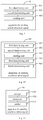
- Fig. 1 it is a method for sending a synchronization signal in an FBMC system provided by an embodiment of the present invention, including:
- the transmitting terminal sends a multicarrier signal to the receiving terminal, and the multicarrier signal is carried on a time-frequency resource location marked by "subcarrier" and "multicarrier symbol".
- a synchronization symbol refers to a symbol for synchronization on one time-frequency resource location.
- the synchronization signal is composed of synchronization symbols located on a plurality of time-frequency resource locations.
- a protection symbol refers to a symbol located on the surrounding of the time-frequency resource location where the synchronization symbol is located and used for protecting the synchronization symbol from being interfered.
- signal transmission may be continuous and may also be discontinuous, for example, in a frequency division duplexing (Frequency Division Duplexing, referred to as FDD) system, the transmission of downlink signals is continuous; in a time division duplexing (Time Division Duplexing, referred to as TDD) system, the signal transmission may be discontinuous.
- FDD Frequency Division Duplexing
- TDD Time Division Duplexing
- Different continuous signal transmissions are discontinuous in terms of time.
- a trailing is respectively generated on a starting position and an end position of the one continuous signal transmission, this segment of trailing reduces the signal transmission rate and is a cost for signal transmission.
- the one continuous signal transmission includes a front trailing, a main body for signal transmission and a post trailing, wherein although having lower power, the front trailing and the post trailing may not be simply discarded, otherwise signal transmission quality and outband leakage may be deteriorated.
- the determining the sending time-frequency resource location of the synchronization symbol pecifically is: determining the multicarrier symbol and the subcarrier where the sending time-frequency resource location of the synchronization symbol is located.
- the sending time-frequency resource location of the synchronization symbol is located on at least one multicarrier symbol within the transmission slot or between adjacent transmission slots.
- a protection symbol for protecting the synchronization symbol may be arranged on at least one multicarrier symbol on the two adjacent sides of the multicarrier symbol where the synchronization symbol is located.
- the sending time-frequency resource location of the synchronization symbol is located on at least one multicarrier symbol of the starting position or the end position of one continuous transmission.
- the protection symbol may be only arranged after the multicarrier symbol where the synchronization symbol is located; when the sending time-frequency resource location of the synchronization symbol is located on at least one multicarrier symbol of the end position of one continuous transmission, the post trailing is transmitted after the synchronization symbol, and the interference of the data symbol on the synchronization symbol does not exist either, therefore, the protection symbol may be only arranged in front of the multicarrier symbol where the synchronization symbol is located.
- the determining a sending time-frequency resource location of a synchronization symbol includes:
- transmultiplexer response is exemplarily illustrated below:
- Table 1 is a typical example of transmultiplexer response of the FBMC system, wherein rows represent the serial numbers of the subcarriers, and columns represent the serial numbers of the multicarrier symbols; elements in the table are called the transmultiplexer response and represent the response of the sending symbol on the sending time-frequency resource location (0,0) to the receiving time-frequency resource locations on the surrounding of the receiving time-frequency resource location (0,0).
- the sending symbol on the sending time-frequency resource location (0,0) is s 0
- the response of the sending time-frequency resource location (0,0) to the receiving time-frequency resource location ( m,n ) is a mn
- the receiving symbol generated by s 0 on the receiving time-frequency resource location ( m,n ) is a mn s 0
- the receiving symbol a mn s 0 will generate interference on the available receiving symbol corresponding to the sending symbol on the sending time-frequency resource location ( m,n ) , wherein m and n are not simultaneously zero.
- j in the elements in Table 1 represents an imaginary unit.
- mutual interference may be generated between symbols on adjacent subcarriers, and basically, no mutual interference is generated between symbols with distances of at least two subcarriers; on the same subcarrier, the mutual interference of the symbols on different multicarrier symbols may arrive at a plurality of multicarrier symbols.
- a non-ignorable transmultiplexer response range is called an interference range of the transmultiplexer in the embodiment, and the interference range of the transmultiplexer includes a frequency domain interference range and a time domain interference range.
- the interference range of the transmultiplexer as shown in table 1 may be a 3 ⁇ 7 range with the central position as a center, specifically, a range formed by 3 time-frequency resource locations on the frequency domain (the subcarrier direction) and 7 time-frequency resource locations on the time domain (the multicarrier symbol direction) with the time-frequency resource location (0, 0) as the center.
- the any two synchronization symbols on the multicarrier symbol when the interval between the sending time-frequency resource locations of any two synchronization symbols on the same multicarrier symbol is greater than or equal to the frequency domain interference range, the any two synchronization symbols on the multicarrier symbol generate no mutual interference, or the generated mutual interference may be omitted.
- the synchronization symbols are placed according to the interference range of the transmultiplexer on the frequency domain, of course, the interval of the synchronization symbols may also be determined according to other manners, for example, one synchronization symbol is placed after every other subcarrier or every few subcarriers.
- a time-frequency resource location having mutual interference with the synchronization symbol is determined; exemplarily, in the FBMC system, the data symbol is generally a pure real number or a pure imaginary number, and the disturbance variables in the receiving symbol corresponding to the data symbol are generally concentrated on the unused imaginary part or real part of the data symbol, therefore, after channel balance is performed on the receiving symbol, inter-symbol interference may be eliminated by an operation of separating the real part from the imaginary part, and the process of eliminating the interference is called a data processing procedure.
- a synchronization procedure is greatly different from the data processing procedure.
- the receiving terminal may not obtain channel information in general, resulting in that the channel balance may not be performed, and thus the inter-symbol interference may not be eliminated by the operation of separating the real part from the imaginary part. Therefore, interference on the synchronization symbol needs to be avoided at the transmitting terminal, namely, the time-frequency resource location having mutual interference with the synchronization symbol needs to be determined.
- step 102 may include: taking the time-frequency resource location with transmultiplexer response of the synchronization symbol within a preset range as the time-frequency resource location having mutual interference with the synchronization symbol according to the transmultiplexer response.
- the preset range may be a threshold
- the transmultiplexer response of the synchronization symbol within the preset range may include: the transmultiplexer response of the synchronization symbol is smaller than or equal to the threshold, and the threshold may be zero or a very small value (which may be omitted).
- the threshold may be set according to experience or actual demand.
- the synchronization symbol is sent on the sending time-frequency resource location of the synchronization symbol, and a protection symbol is sent on the time-frequency resource location having mutual interference with the synchronization symbol.
- the protection symbol is sent on the time-frequency resource location having mutual interference with the synchronization symbol for avoiding the interference of the data symbol on the synchronization symbol.
- the method may further include: determining a value of the synchronization symbol.
- the value of each synchronization symbol may be a real number or an imaginary number randomly generated by the transmitting terminal, in order to reduce the complexity of a frequency synchronization algorithm at the receiving terminal, optionally, the values of the synchronization symbols on the same multicarrier symbol are symmetrical with respect to the central frequency of the synchronization signal. Further optionally, the values of the synchronization symbols on the same multicarrier symbol are real numbers.
- the method for reducing the complexity of the frequency synchronization algorithm at the receiving terminal may refer to the following specific embodiment part.
- the method may further include: determining a value of the protection symbol.
- the interference of the data symbol on the synchronization symbol may be avoided by attanging the protection symbol on the surrounding of the synchronization symbol, specifically, the disturbance variable of the value of the protection symbol on the synchronization symbol is zero.
- the value of the protection symbol is zero.
- the determining a value of the protection symbol may further include:
- the value of the protection symbol may be zero and may also be a non-zero value, which is set according to the transmultiplexer response, the sending time-frequency resource location of the synchronization symbol, the time-frequency resource location having mutual interference with the synchronization symbol and the property that the disturbance variable of the value of the protection symbol on the synchronization symbol is zero, and specific reference may be made to related part in the following first embodiment.
- step 103 may specifically include: determining a mapping interval of the synchronization symbol on the frequency domain, and placing the synchronization symbol according to the mapping interval and the value of the synchronization symbol.
- the mapping interval may be set according to experience or demands in an actual application process. Specifically, in the interference range, the larger the mapping interval is, the smaller the interference between adjacent synchronization symbols is, the more accurate the synchronization of the FBMC system is, but the larger the mapping interval is, the cost of the synchronization signal will be increased, or the number of the synchronization symbols in the synchronization signal is relatively small, resulting in inaccurate synchronization; therefore, the mapping interval of the synchronization symbols on the frequency domain may be determined according to the balance of synchronization precision and the cost. Further, the time-frequency resource locations having mutual interference with the synchronization symbol are different as mapping intervals of the synchronization symbols on the frequency domain are different.
- the method for sending a synchronization signal in the FBMC system provided by the embodiment of the present invention, by determining the sending time-frequency resource location of the synchronization symbol and the time-frequency resource location having mutual interference with the synchronization symbol, sending the synchronization symbol on the sending time-frequency resource location of the synchronization symbol, and sending the protection symbol on the time-frequency resource location having mutual interference with the synchronization symbol, synchronization of the FBMC system is achieved using one synchronization signal, thereby the cost of the synchronization signal is saved and the spectral efficiency is improved.
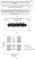
- FIG. 3 it is a schematic diagram of a multicarrier signal containing a synchronization signal, wherein a horizontal axis represents the serial number of the multicarrier symbol, and a vertical axis represents the serial number of the subcarrier; each grid represents a time-frequency resource location; a grid marked by an oblique line represents that the symbol on the time-frequency resource location is a synchronization symbol; a blank grid represents that the protection symbol is sent on the time-frequency resource location; a grid marked in gray represents that the symbol on the time-frequency resource location is a data symbol.
- the time-frequency resource location where the synchronization signal is located occupies M -2 subcarriers (the serial numbers of the subcarriers are 1 ⁇ M -2) in total, and the serial number of the multicarrier symbol where the synchronization symbol is located is n 0 .
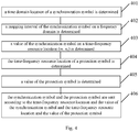
- FIG. 4 it is a method for sending a synchronization signal in an FBMC system provided by an embodiment of the present invention, including:
- Example 1 referring to Fig. 3 , the synchronization symbols d m,n 0 are placed on all subcarriers.
- Example 2 referring to Fig. 5 , one synchronization symbol is placed every other subcarrier.
- the method for determining the mapping interval of the synchronization symbol on the frequency domain is not limited in the embodiment of the present invention, for example, the distance between two adjacent synchronization symbols may be different.
- a value of the synchronization symbol on a time-frequency resource location ( m , n 0 ) is determined; exemplarily, the value of the synchronization symbol on the time-frequency resource location ( m, n 0 ) may be a random number, and in order to reduce the complexity of the frequency synchronization algorithm at the receiving terminal, the embodiment is illustrated by taking it as an example that the values of the synchronization symbols on the same multicarrier symbol are symmetrical with respect to the central frequency of the synchronization signal and the values of the synchronization symbols on the same multicarrier symbol are real numbers.
- the time-frequency resource location of a protection symbol is determined; specifically, on the time domain, the range of protection symbols on two adjacent sides of the time domain location of the synchronization symbol should be larger than the time domain interference range of the transmultiplexer; for example, in Fig. 3 , protection symbols on Ng subcarriers are contained on both sides of a subcarrier n 0 , wherein Ng refers to the time domain interference range of the transmultiplexer.
- the range of the protection symbols on the frequency domain is determined according to the frequency domain interference range of the transmultiplexer; for example, the protection symbols are located on the subcarrier 0 and the subcarrier M in Fig. 3 .
- step 403 and step 404 may be inverted.
- a value of the protection symbol is determined; exemplarily, the value of the protection symbol on the time-frequency resource location ( m, n ) is marked as c m,n . c m,n satisfies the property that the disturbance variable on the synchronization symbol is zero.
- the time-frequency resource location where the synchronization symbol is located is ( m 0 , n 0 )
- the time-frequency resource location of the protection symbol having interference on the synchronization symbol on the time-frequency resource location ( m 0 , n 0 ) is ( m, n )
- the location set of all the protection symbols having interference on the synchronization symbol on the time-frequency resource location (mo, no) is ⁇ m 0 , n 0
- the value of transmultiplexer response generated by the protection symbol on the time-frequency resource location ( m, n ) on the time-frequency resource location ( m 0 , n 0 ) is t m 0 , n 0 - n
- the time-frequency resource location ( m, n ) and the set ⁇ m 0 , n 0 of the protection symbol are determined by step 404, and the value of the transmultiplexer response t m 0 , n 0
- Example 1 the value of c m,n is zero. Referring to Fig. 3 and Fig. 5 , the protection symbols shown in the figures are zero.
- Example 2 the value of c m,n is a non-zero numerical value conforming to a certain rule.
- Table 2 it is a schematic diagram of a location where the synchronization symbol and the protection symbol on a time-frequency two-dimensional resource location is located, and synchronization symbols d m 0 ,n 0 and d m 0 +2, n 0 are sent respectively on the time-frequency resource location ( m 0 , n 0 ) and on the time-frequency resource location ( m 0 +2, n 0 ) within a range of 3 ⁇ 5 time-frequency two-dimensional resource grids, and protection signals are sent on other time-frequency resource locations.
- the range of the 3 ⁇ 5 time-frequency two-dimensional resource grids is specifically a range formed by 3 time-frequency resource locations on the frequency domain (the subcarrier direction) and 5 time-frequency resource locations on the time domain (the multicarrier symbol direction).
- Table 2 c m 0 -1, n 0 -1 c m 0 - 1 , n 0 c m 0 - 1 , n 0 +1 c m 0 , n 0 -1 d m 0 , n 0 c m 0 ,n 0 +1 c m 0 +1 ,n 0 -1 c m 0 - 1 ,n 0 c m 0 +1 ,n 0 +1 c m 0 +2 ,n 0 -1 d m 0 +2, n 0 c m 0 +2, n 0 +1 c m 0 +3, n 0 -1 c m 0
- Example 3 the value of c m,n is a non-zero numerical value conforming to a certain rule or is zero.
- the synchronization symbol and the protection symbol are sent according to the time-frequency resource location and the value of the synchronization symbol and the time-frequency resource location and the value of the protection symbol.
- the above-mentioned method may be used for sending the synchronization signal to reduce the complexity of the frequency synchronization algorithm at the receiving terminal, which will be illustrated below:
- ⁇ refers to a delay time.
- the distance of the two sampling points x +[ m ] and x -[ m ] has great influence on a frequency offset estimation result, in general, the frequency offset estimated by the closer sampling points is susceptible to interference and noise, therefore, by adjusting the weight coefficient, the frequency offset result estimated by the closer sampling points has a smaller weight coefficient through and the frequency offset result estimated by the farther sampling points has a larger weight coefficient. So that an averaged result is more accurate.
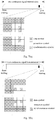
- the difference from embodiment 1 and embodiment 2 lies in that, the synchronization signal in the present embodiment is located at a starting position or an end position of one continuous signal transmission, protection symbols are arranged on both sides of the synchronization symbol in the synchronization signal, but the time-frequency resource locations of the protection symbols are asymmetric.
- Fig. 7(c) it is a synchronization symbol based on embodiment 1
- Fig. 7(d) it is a synchronization symbol based on embodiment 2.
- the synchronization symbol based on embodiment 1 in the present embodiment may reduce the cost of the synchronization signal; or compared with the synchronization symbol determined in embodiment 2, the synchronization symbol based on embodiment 2 in the present embodiment may reduce the cost of the synchronization signal.
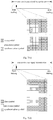
- the difference from embodiment 1 and embodiment 2 lies in that, the synchronization signal in the present embodiment is located at a starting position or an end position of one continuous signal transmission, and the protection symbol is only arranged on one side of the synchronization symbol in the synchronization signal.
- Fig. 8(c) it is a synchronization symbol based on embodiment 1
- Fig. 8(d) it is a synchronization symbol based on embodiment 2.
- the protection symbol is only arranged after the synchronization symbol.
- Compared the 1) in the present embodiment with the 1) in embodiment 3, or compared the 2) in the present embodiment with the 2) in embodiment 3, may reduce the cost of the synchronization signal.
- the method for sending the synchronization signal in the FBMC system provided by the embodiment of the present invention, by determining the sending time-frequency resource location of the synchronization symbol, determining the time-frequency resource location having mutual interference with the synchronization symbol, sending the synchronization symbol on the sending time-frequency resource location of the synchronization symbol, and sending the protection symbol on the time-frequency resource location having mutual interference with the synchronization symbol, synchronization of the FBMC system is achieved using one synchronization signal, thereby the cost of the synchronization signal is saved and the spectral efficiency is improved.
- FIG. 9 it is an appararus 90 for sending a synchronization signal provided by an embodiment of the present invention, which may be applied to an FBMC system for implementing the method for sending the synchronization signal as shown in Fig. 1 , and the apparatus 90 may include:
- the sending time-frequency resource location of the synchronization symbol is located on at least one multicarrier symbol of a starting position or an end position of one continuous signal transmission.
- the second determining unit 902 is specifically configured to utilize the time-frequency resource location with transmultiplexer response of the synchronization symbol within a preset range as the time-frequency resource location having mutual interference with the synchronization symbol according to the transmultiplexer response.
- the time-frequency resource location having mutual interference with the synchronization symbol is located on at least one multicarrier symbol after the multicarrier symbol where the synchronization symbol is located; or, when the sending time-frequency resource location of the synchronization symbol is located on at least one multicarrier symbol of an end position of one continuous signal transmission, the time-frequency resource location having mutual interference with the synchronization symbol is located on at least one multicarrier symbol before the multicarrier symbol where the synchronization symbol is located.
- the first determining unit 901 is specifically configured to, determine a frequency domain interference range of the synchronization symbol according to the transmultiplexer response; and determine the sending time-frequency resource location of the synchronization symbol according to the frequency domain interference range, wherein an interval between the sending time-frequency resource locations of any two synchronization symbols on the same multicarrier symbol is greater than or equal to the frequency domain interference range.
- the apparatus 90 further includes:
- the values of the synchronization symbols on the same multicarrier symbol are real numbers.
- the apparatus 90 further includes:
- the value of the protection symbol is zero.
- the fourth determining unit 905 is specifically configured to determine the value of the protection symbol according to the transmultiplexer response, the sending time-frequency resource location of the synchronization symbol and the time-frequency resource location having mutual interference with the synchronization symbol.
- the apparatus for sending the synchronization signal in the FBMC system provided by the embodiment of the present invention, by determining the sending time-frequency resource location of the synchronization symbol, determining the time-frequency resource location having mutual interference with the synchronization symbol, sending the synchronization symbol on the sending time-frequency resource location of the synchronization symbol, and sending the protection symbol on the time-frequency resource location having mutual interference with the synchronization symbol, synchronization of the FBMC system is achieved using one synchronization signal, thereby the cost of the synchronization signal is saved and the spectral efficiency is improved.
- FIG. 11 it is an apparatus 90 for sending a synchronization signal provided by an embodiment of the present invention, which may be applied to an FBMC system for implementing the method for sending a synchronization signal as shown in Fig. 1 , and the apparatus 90 may include a memory 1101, a processor 1102 and a sender 1103, wherein, the memory 1101 is configured to store a group of codes, and the codes are used for controlling the processor 1102 to implement the following actions:
- the sending time-frequency resource location of the synchronization symbol is located on at least one multicarrier symbol of a starting position or an end position of one continuous signal transmission.
- the processor 1102 is specifically configured to utilize the time-frequency resource location with transmultiplexer response of the synchronization symbol within a preset range as the time-frequency resource location having mutual interference with the synchronization symbol according to the transmultiplexer response.
- the time-frequency resource location having mutual interference with the synchronization symbol is located on at least one multicarrier symbol after the multicarrier symbol where the synchronization symbol is located; or, when the sending time-frequency resource location of the synchronization symbol is located on at least one multicarrier symbol of an end position of one continuous signal transmission, the time-frequency resource location having mutual interference with the synchronization symbol is located on at least one multicarrier symbol before the multicarrier symbol where the synchronization symbol is located.
- the processor 1102 is specifically configured to, determine a frequency domain interference range of the synchronization symbol according to transmultiplexer response; and determine the sending time-frequency resource location of the synchronization symbol according to the frequency domain interference range, wherein an interval between the sending time-frequency resource locations of any two synchronization symbols on the same multicarrier symbol is larger than or equal to the frequency domain interference range.
- the processor 1102 is further configured to determine a value of the synchronization symbol, wherein the values of the synchronization symbols on the same multicarrier symbol are symmetrical with respect to the central frequency of the synchronization signal.
- the values of the synchronization symbols on the same multicarrier symbol are real numbers.
- the processor 1102 is further configured to determine a value of the protection symbol, wherein the disturbance variable of the value of the protection symbol on the synchronization symbol is zero.
- the value of the protection symbol is zero.
- the processor 1102 is specifically configured to determine the value of the protection symbol according to the transmultiplexer response, the sending time-frequency resource location of the synchronization symbol and the time-frequency resource location having mutual interference with the synchronization symbol.
- the apparatus for sending the synchronization signal in the FBMC system provided by the embodiment of the present invention, by determining the sending time-frequency resource location of the synchronization symbol, determining the time-frequency resource location having mutual interference with the synchronization symbol, sending the synchronization symbol on the sending time-frequency resource location of the synchronization symbol, and sending the protection symbol on the time-frequency resource location having mutual interference with the synchronization symbol, synchronization of the FBMC system is achieved using one synchronization signal, thereby the cost of the synchronization signal is saved and the spectral efficiency is improved.
- the disclosed apparatus and method may be implemented in other manners.
- the apparatus embodiments described above are merely exemplary, e.g., the division of the units is only a logic function division, other division manners may exist in practical implementation, for example, a plurality of units or components may be combined, or some features may be omitted or not implemented.
- the displayed or discussed mutual coupling or direct coupling or communication connection may be indirect coupling or communication connection of apparatuses or units through some interfaces, and may be in electrical, mechanical or other forms.
- the units described as separate components may be separated physically or not, components displayed as units may be physical units or not, namely, may be located in one place, or may be distributed on a plurality of network units. A part of or all of the units may be selected to implement the purposes of the technical solutions in the embodiments according to actual demand.
- the functional units in the embodiments of the present invention may be integrated in a processing unit, or the units singly exist physically, or two or more units are integrated in one unit.
- the above-mentioned integrated unit may be implemented in a hardware form and may also be implemented in a form of hardware and software functional units.
- the above-mentioned integrated unit implemented in the form of the software functional unit may be stored in a computer readable storage medium.
- the above-mentioned software functional unit is stored in a storage medium, including a plurality of instructions for enabling a computer device (may be a personnel computer, a server, or a network device or the like) to execute all or a part of the steps of the method in the embodiments of the present invention.
- the foregoing storage medium includes a variety of media capable of storing program codes, such as a USB disk, a mobile hard disk, a read-only memory (Read-Only Memory, referred to as ROM), a random access memory (Random Access Memory, referred to as RAM), a magnetic disk, an optical disk or the like.
Landscapes
- Engineering & Computer Science (AREA)
- Signal Processing (AREA)
- Computer Networks & Wireless Communication (AREA)
- Mobile Radio Communication Systems (AREA)
Claims (20)
- Verfahren zum Senden eines Synchronisationssignals in einem Filterbank-Mehrfachträger-System, FBMC-System, das Folgendes umfasst:Bestimmen (101) durch ein übertragendes Endgerät eines ersten sendenden Zeit-Frequenz-Betriebsmittelorts eines Synchronisationssymbols;Bestimmen (102) durch das übertragende Endgerät eines zweiten sendenden Zeit-Frequenz-Betriebsmittelorts, auf dem ein Datensymbol eine wechselseitige Störung mit dem Synchronisationssymbol aufweisen wird; undSenden (103) durch das übertragende Endgerät des Synchronisationssymbols auf dem ersten sendenden Zeit-Frequenz-Betriebsmittelort des Synchronisationssymbols und Senden eines Schutzsymbols auf dem zweiten sendenden Zeit-Frequenz-Betriebsmittelort.
- Verfahren nach Anspruch 1, wobei
sich der erste sendende Zeit-Frequenz-Betriebsmittelort des Synchronisationssymbols auf wenigstens einem Mehrfachträgersymbol einer Startposition oder einer Endposition einer kontinuierlichen Signalübertragung befindet. - Verfahren nach Anspruch 1 oder 2, wobei das Bestimmen (102) durch ein übertragendes Endgerät eines zweiten sendenden Zeit-Frequenz-Betriebsmittelorts Folgendes umfasst:Nutzen des Zeit-Frequenz-Betriebsmittelorts mit Transmultiplexerantwort des Synchronisationssymbols innerhalb eines voreingestellten Bereichs als den zweiten sendenden Zeit-Frequenz-Betriebsmittelort gemäß der Transmultiplexerantwort.
- Verfahren nach Anspruch 2, wobei
wenn sich der erste sendende Zeit-Frequenz-Betriebsmittelort des Synchronisationssymbols auf wenigstens einem Mehrfachträgersymbol einer Startposition einer kontinuierlichen Signalübertragung befindet, sich der zweite sendende Zeit-Frequenz-Betriebsmittelort auf wenigstens einem Mehrfachträgersymbol nach dem Mehrfachträgersymbol befindet, wo sich das Synchronisationssymbol befindet;
oder wenn sich der erste sendende Zeit-Frequenz-Betriebsmittelort des Synchronisationssymbols auf wenigstens einem Mehrfachträgersymbol einer Endposition einer kontinuierlichen Signalübertragung befindet, sich der zweite sendende Zeit-Frequenz-Betriebsmittelort auf wenigstens einem Mehrfachträgersymbol vor dem Mehrfachträgersymbol befindet, wo sich das Synchronisationssymbol befindet. - Verfahren nach Anspruch 1, wobei das Bestimmen (101) durch ein sendendes Endgerät eines ersten sendenden Zeit-Frequenz-Betriebsmittelorts eines Synchronisationssymbols Folgendes umfasst:Bestimmen eines Frequenzdomänenstörungsbereichs des Synchronisationssymbols gemäß der Transmultiplexerantwort; undBestimmen des ersten sendenden Zeit-Frequenz-Betriebsmittelorts des Synchronisationssymbols gemäß dem Frequenzdomänenstörungsbereich, wobei ein Abstand zwischen den ersten sendenden Zeit-Frequenz-Betriebsmittelorten zweier beliebiger Synchronisationssymbole auf demselben Mehrfachträgersymbol größer als der oder gleich dem Frequenzdomänenstörungsbereich ist.
- Verfahren nach Anspruch 1, das ferner Folgendes umfasst: Bestimmen eines Werts des Synchronisationssymbols, wobei die Werte der Synchronisationssymbole auf demselben Mehrfachträgersymbol hinsichtlich der Mittelfrequenz des Synchronisationssignals symmetrisch sind.
- Verfahren nach Anspruch 6, wobei die Werte der Synchronisationssymbole auf demselben Mehrfachträgersymbol reelle Zahlen sind.
- Verfahren nach Anspruch 1, das ferner Folgendes umfasst: Bestimmen eines Werts des Schutzsymbols, wobei die Störung des Werts des Schutzsymbols auf dem Synchronisationssymbol null ist.
- Verfahren nach Anspruch 8, wobei der Wert des Schutzsymbols null ist.
- Verfahren nach Anspruch 8, wobei das Bestimmen eines Werts des Schutzsymbols Folgendes umfasst:Bestimmen des Werts des Schutzsymbols gemäß der Transmultiplexerantwort, dem ersten sendenden Zeit-Frequenz-Betriebsmittelort des Synchronisationssymbols und dem zweiten sendenden Zeit-Frequenz-Betriebsmittelort.
- Vorrichtung zum Senden eines Synchronisationssignals für ein Filterbank-Mehrfachträger-System, FBMC-System, die Folgendes umfasst:eine erste Bestimmungseinheit (901), die konfiguriert ist, einen ersten sendenden Zeit-Frequenz-Betriebsmittelort eines Synchronisationssymbols zu bestimmen;eine zweite Bestimmungseinheit (902), die konfiguriert ist, einen zweiten sendenden Zeit-Frequenz-Betriebsmittelort zu bestimmen, auf dem ein Datensymbol eine wechselseitige Störung mit dem Synchronisationssymbol aufweisen wird; undeine Sendeeinheit (903), die konfiguriert ist, das Synchronisationssymbol auf dem ersten sendenden Zeit-Frequenz-Betriebsmittelort des Synchronisationssymbols zu senden und ein Schutzsymbol auf dem zweiten sendenden Zeit-Frequenz-Betriebsmittelort zu senden.
- Vorrichtung nach Anspruch 11, wobei
sich der erste sendende Zeit-Frequenz-Betriebsmittelort des Synchronisationssymbols auf wenigstens einem Mehrfachträgersymbol einer Startposition oder einer Endposition einer kontinuierlichen Signalübertragung befindet. - Vorrichtung nach Anspruch 11 oder 12, wobei die zweite Bestimmungseinheit (902) insbesondere konfiguriert ist, den Zeit-Frequenz-Betriebsmittelort mit Transmultiplexerantwort des Synchronisationssymbols innerhalb eines voreingestellten Bereichs als den zweiten sendenden Zeit-Frequenz-Betriebsmittelort gemäß der Transmultiplexerantwort zu benutzen.
- Vorrichtung nach Anspruch 12, wobei,
wenn sich der erste sendende Zeit-Frequenz-Betriebsmittelort des Synchronisationssymbols auf wenigstens einem Mehrfachträgersymbol einer Startposition einer kontinuierlichen Signalübertragung befindet, sich der zweite sendende Zeit-Frequenz-Betriebsmittelort auf wenigstens einem Mehrfachträgersymbol nach dem Mehrfachträgersymbol befindet, wo sich das Synchronisationssymbol befindet;
oder wenn sich der erste sendende Zeit-Frequenz-Betriebsmittelort des Synchronisationssymbols auf wenigstens einem Mehrfachträgersymbol einer Endposition einer kontinuierlichen Signalübertragung befindet, sich der zweite sendende Zeit-Frequenz-Betriebsmittelort auf wenigstens einem Mehrfachträgersymbol vor dem Mehrfachträgersymbol befindet, wo sich das Synchronisationssymbol befindet. - Vorrichtung nach Anspruch 11, wobei die erste Bestimmungseinheit (901) insbesondere konfiguriert ist,
einen Frequenzdomänenstörungsbereich des Synchronisationssymbols gemäß der Transmultiplexerantwort zu bestimmen; und
den ersten sendenden Zeit-Frequenz-Betriebsmittelort des Synchronisationssymbols gemäß dem Frequenzdomänenstörungsbereich zu bestimmen, wobei ein Abstand zwischen den ersten sendenden Zeit-Frequenz-Betriebsmittelorten zweier beliebiger Synchronisationssymbole auf demselben Mehrfachträgersymbol größer als der oder gleich dem Frequenzdomänenstörungsbereich ist. - Vorrichtung nach Anspruch 11, die ferner Folgendes umfasst:eine dritte Bestimmungseinheit (904), die konfiguriert ist, einen Wert des Synchronisationssymbols zu bestimmen, wobei die Werte der Synchronisationssymbole auf demselben Mehrfachträgersymbol hinsichtlich der Mittelfrequenz des Synchronisationssignals symmetrisch sind.
- Vorrichtung nach Anspruch 16, wobei die Werte der Synchronisationssymbole auf demselben Mehrfachträgersymbol reelle Zahlen sind.
- Vorrichtung nach Anspruch 11, die ferner Folgendes umfasst:eine vierte Bestimmungseinheit (905), die konfiguriert ist, einen Wert des Schutzsymbols zu bestimmen, wobei die Störung des Werts des Schutzsymbols auf dem Synchronisationssymbol null ist.
- Vorrichtung nach Anspruch 18, wobei der Wert des Schutzsymbols null ist.
- Vorrichtung nach Anspruch 18, wobei die vierte Bestimmungseinheit (905) insbesondere konfiguriert ist, den Wert des Schutzsymbols gemäß der Transmultiplexerantwort, dem ersten sendenden Zeit-Frequenz-Betriebsmittelort des Synchronisationssymbols und dem zweiten sendenden Zeit-Frequenz-Betriebsmittelort zu bestimmen.
Applications Claiming Priority (2)
| Application Number | Priority Date | Filing Date | Title |
|---|---|---|---|
| CN201310271847.9A CN104253680B (zh) | 2013-06-27 | 2013-06-27 | 一种fbmc系统中同步信号的发送方法和装置 |
| PCT/CN2014/081001 WO2014206348A1 (zh) | 2013-06-27 | 2014-06-27 | 一种fbmc系统中同步信号的发送方法和装置 |
Publications (3)
| Publication Number | Publication Date |
|---|---|
| EP2999183A1 EP2999183A1 (de) | 2016-03-23 |
| EP2999183A4 EP2999183A4 (de) | 2016-05-18 |
| EP2999183B1 true EP2999183B1 (de) | 2017-11-15 |
Family
ID=52141108
Family Applications (1)
| Application Number | Title | Priority Date | Filing Date |
|---|---|---|---|
| EP14817870.0A Active EP2999183B1 (de) | 2013-06-27 | 2014-06-27 | Verfahren zur übertragung von synchronisierungssignalen und vorrichtung in einem fbmc-system |
Country Status (4)
| Country | Link |
|---|---|
| US (1) | US9906394B2 (de) |
| EP (1) | EP2999183B1 (de) |
| CN (1) | CN104253680B (de) |
| WO (1) | WO2014206348A1 (de) |
Families Citing this family (13)
| Publication number | Priority date | Publication date | Assignee | Title |
|---|---|---|---|---|
| KR102275054B1 (ko) * | 2014-06-18 | 2021-07-09 | 삼성전자주식회사 | Fbmc 시스템에서 심볼을 송수신하는 기법 |
| CN105847209B (zh) * | 2015-01-16 | 2020-09-29 | 北京三星通信技术研究有限公司 | 基于滤波器组多载波调制的通信方法和装置 |
| KR102299663B1 (ko) * | 2015-02-24 | 2021-09-08 | 삼성전자 주식회사 | 이동 통신 시스템에서 동기화 방법 및 장치 |
| CN107113126B (zh) * | 2015-06-09 | 2020-03-10 | 华为技术有限公司 | 一种信号处理方法、装置及系统 |
| CN106572043B (zh) * | 2015-10-09 | 2019-12-20 | 普天信息技术有限公司 | 一种传输消息的方法和系统 |
| CN106230761B (zh) * | 2016-07-22 | 2019-05-14 | 中南大学 | 一种基于零自相关码的fbmc系统的同步方法 |
| CN106301572B (zh) * | 2016-08-08 | 2019-08-23 | 上海交通大学 | 用于光fbmc传输系统的低开支信道估计方法及应用系统 |
| KR20190049864A (ko) * | 2016-09-23 | 2019-05-09 | 후아웨이 테크놀러지 컴퍼니 리미티드 | 자원 매핑 방법, 송신단 및 수신단 |
| SG11201908333WA (en) | 2017-03-15 | 2019-10-30 | Guangdong Oppo Mobile Telecommunications Corp Ltd | Method and device for transmitting synchronization signal |
| CN109474984B (zh) * | 2017-09-07 | 2021-06-04 | 展讯通信(上海)有限公司 | 主同步信号检测方法及装置、用户终端及可读存储介质 |
| CN108650205B (zh) * | 2018-04-10 | 2020-10-02 | 东南大学 | 适用于fbmc传输的并行数据处理方法及装置 |
| CN108809880B (zh) * | 2018-04-23 | 2020-11-20 | 东南大学 | 一种低复杂度的mimo-fbmc系统数据收发方法及装置 |
| US20240405944A1 (en) * | 2021-09-28 | 2024-12-05 | Beijing Xiaomi Mobile Software Co., Ltd. | Method for configuring information and device |
Family Cites Families (6)
| Publication number | Priority date | Publication date | Assignee | Title |
|---|---|---|---|---|
| CN1131653C (zh) * | 2000-03-27 | 2003-12-17 | 信息产业部电信科学技术研究院 | 一种码分多址数字移动通信系统的小区初始搜索方法 |
| US7876842B2 (en) * | 2006-04-14 | 2011-01-25 | Panasonic Corporation | Multicarrier transmission method, multicarrier modulation signal transmission apparatus, multicarrier modulation signal reception apparatus, multicarrier modulation signal transmission method, and pilot signal generation method |
| CN101860497B (zh) * | 2010-05-24 | 2013-06-05 | 北京科技大学 | 一种利用改进球译码算法实现fbmc系统的均衡的方法 |
| FR2973187B1 (fr) * | 2011-03-25 | 2013-11-15 | Commissariat Energie Atomique | Procede de traitement d'un signal multiporteuses a bancs de filtre pour la synchronisation par preambule |
| CN102497348A (zh) * | 2011-12-18 | 2012-06-13 | 浙江大学 | 一种提高滤波器组多载波系统抗时域干扰能力的方法 |
| CN103368889B (zh) * | 2012-03-29 | 2016-06-29 | 上海贝尔股份有限公司 | 滤波器组多载波信号发射及信道估计的方法和装置 |
-
2013
- 2013-06-27 CN CN201310271847.9A patent/CN104253680B/zh active Active
-
2014
- 2014-06-27 WO PCT/CN2014/081001 patent/WO2014206348A1/zh not_active Ceased
- 2014-06-27 EP EP14817870.0A patent/EP2999183B1/de active Active
-
2015
- 2015-12-08 US US14/962,856 patent/US9906394B2/en active Active
Non-Patent Citations (1)
| Title |
|---|
| None * |
Also Published As
| Publication number | Publication date |
|---|---|
| CN104253680B (zh) | 2018-07-31 |
| US20160094377A1 (en) | 2016-03-31 |
| EP2999183A4 (de) | 2016-05-18 |
| CN104253680A (zh) | 2014-12-31 |
| US9906394B2 (en) | 2018-02-27 |
| WO2014206348A1 (zh) | 2014-12-31 |
| EP2999183A1 (de) | 2016-03-23 |
Similar Documents
| Publication | Publication Date | Title |
|---|---|---|
| EP2999183B1 (de) | Verfahren zur übertragung von synchronisierungssignalen und vorrichtung in einem fbmc-system | |
| EP3116151B1 (de) | Benutzerendgerät, funkbasisstation, funkkommunikationsverfahren und funkkommunikationssystem | |
| US20260025300A1 (en) | Methods and systems for generating a low peak-to-average power ratio (papr) data and reference signal | |
| JP6294484B2 (ja) | マルチキャリア信号の受信機および受信機方法 | |
| Gaspar et al. | Low complexity GFDM receiver based on sparse frequency domain processing | |
| EP2666269B1 (de) | Empfänger und entsprechendes Verfahren zur bestimmung der Kanalschätzung | |
| EP2721791B1 (de) | Vorrichtung und verfahren zum empfangen eines signals in einem drahtlosen kommunikationssystem | |
| EP3113395B1 (de) | Drahtlose basisstation, benutzerendgerät, drahtloskommunikationsverfahren und drahtloskommunikationssystem | |
| EP2777185B1 (de) | Verfahren und knoten zur kanalschätzung | |
| EP3211811A1 (de) | Verfahren und vorrichtung zum empfangen von signalen auf basis der interferenzmessung in einem mobilkommunikationssystem | |
| US20140086266A1 (en) | LTE-Advanced Primary Synchronization Signal Detection | |
| US20170265202A1 (en) | Time domain pilot of single-carrier mimo system and synchronization method thereof | |
| JP5892073B2 (ja) | 通信機および通信方法 | |
| EP1475932B1 (de) | Interferenzsignalerkennung und Kanalschätzung für drahtlose Kommunikationsnetze | |
| EP3573275B1 (de) | Signalübertragungs- und empfangsverfahren, vorrichtung und system in der drahtlosen kommunikation | |
| EP3195503B1 (de) | Störungsschätzung für lte-empfänger | |
| EP3285450B1 (de) | Verfahren und vorrichtung zur kompensation von antennenfehlern | |
| WO2022081114A1 (en) | Method and apparatus for channel estimation in mimo-ofdm systems based on phase correction in pilot depatterning | |
| CN108390837B (zh) | 一种lte下行信道估计方法 | |
| EP3235206B1 (de) | Aufheben eines schutzintervall im zeitbereich durch verzerrung von datensubträgern im frequenzbereich | |
| Kalwar et al. | Analysis of effect of carrier frequency offset on performance of LTE uplink | |
| KR101160526B1 (ko) | 직교 주파수 분할 다중 접속 시스템에서 채널 추정 방법 | |
| JP6701545B2 (ja) | 無線通信システム | |
| Häring | Intrinsic interference-aware adaptive FBMC transmission with automatic modulation classification | |
| Sagong et al. | A novel blind interference cancellation receiver for LTE uplink SC-FDMA systems |
Legal Events
| Date | Code | Title | Description |
|---|---|---|---|
| PUAI | Public reference made under article 153(3) epc to a published international application that has entered the european phase |
Free format text: ORIGINAL CODE: 0009012 |
|
| 17P | Request for examination filed |
Effective date: 20151214 |
|
| AK | Designated contracting states |
Kind code of ref document: A1 Designated state(s): AL AT BE BG CH CY CZ DE DK EE ES FI FR GB GR HR HU IE IS IT LI LT LU LV MC MK MT NL NO PL PT RO RS SE SI SK SM TR |
|
| AX | Request for extension of the european patent |
Extension state: BA ME |
|
| REG | Reference to a national code |
Ref country code: DE Ref legal event code: R079 Ref document number: 602014017380 Country of ref document: DE Free format text: PREVIOUS MAIN CLASS: H04L0027340000 Ipc: H04L0005000000 |
|
| A4 | Supplementary search report drawn up and despatched |
Effective date: 20160414 |
|
| RIC1 | Information provided on ipc code assigned before grant |
Ipc: H04L 27/26 20060101ALI20160408BHEP Ipc: H04L 5/00 20060101AFI20160408BHEP |
|
| DAX | Request for extension of the european patent (deleted) | ||
| RAP1 | Party data changed (applicant data changed or rights of an application transferred) |
Owner name: HUAWEI TECHNOLOGIES CO., LTD. |
|
| GRAP | Despatch of communication of intention to grant a patent |
Free format text: ORIGINAL CODE: EPIDOSNIGR1 |
|
| INTG | Intention to grant announced |
Effective date: 20170531 |
|
| GRAS | Grant fee paid |
Free format text: ORIGINAL CODE: EPIDOSNIGR3 |
|
| GRAA | (expected) grant |
Free format text: ORIGINAL CODE: 0009210 |
|
| AK | Designated contracting states |
Kind code of ref document: B1 Designated state(s): AL AT BE BG CH CY CZ DE DK EE ES FI FR GB GR HR HU IE IS IT LI LT LU LV MC MK MT NL NO PL PT RO RS SE SI SK SM TR |
|
| REG | Reference to a national code |
Ref country code: CH Ref legal event code: EP Ref country code: GB Ref legal event code: FG4D Ref country code: AT Ref legal event code: REF Ref document number: 947253 Country of ref document: AT Kind code of ref document: T Effective date: 20171115 |
|
| REG | Reference to a national code |
Ref country code: IE Ref legal event code: FG4D |
|
| REG | Reference to a national code |
Ref country code: DE Ref legal event code: R096 Ref document number: 602014017380 Country of ref document: DE |
|
| REG | Reference to a national code |
Ref country code: NL Ref legal event code: MP Effective date: 20171115 |
|
| REG | Reference to a national code |
Ref country code: LT Ref legal event code: MG4D |
|
| REG | Reference to a national code |
Ref country code: AT Ref legal event code: MK05 Ref document number: 947253 Country of ref document: AT Kind code of ref document: T Effective date: 20171115 |
|
| PG25 | Lapsed in a contracting state [announced via postgrant information from national office to epo] |
Ref country code: NO Free format text: LAPSE BECAUSE OF FAILURE TO SUBMIT A TRANSLATION OF THE DESCRIPTION OR TO PAY THE FEE WITHIN THE PRESCRIBED TIME-LIMIT Effective date: 20180215 Ref country code: SE Free format text: LAPSE BECAUSE OF FAILURE TO SUBMIT A TRANSLATION OF THE DESCRIPTION OR TO PAY THE FEE WITHIN THE PRESCRIBED TIME-LIMIT Effective date: 20171115 Ref country code: LT Free format text: LAPSE BECAUSE OF FAILURE TO SUBMIT A TRANSLATION OF THE DESCRIPTION OR TO PAY THE FEE WITHIN THE PRESCRIBED TIME-LIMIT Effective date: 20171115 Ref country code: FI Free format text: LAPSE BECAUSE OF FAILURE TO SUBMIT A TRANSLATION OF THE DESCRIPTION OR TO PAY THE FEE WITHIN THE PRESCRIBED TIME-LIMIT Effective date: 20171115 Ref country code: ES Free format text: LAPSE BECAUSE OF FAILURE TO SUBMIT A TRANSLATION OF THE DESCRIPTION OR TO PAY THE FEE WITHIN THE PRESCRIBED TIME-LIMIT Effective date: 20171115 Ref country code: NL Free format text: LAPSE BECAUSE OF FAILURE TO SUBMIT A TRANSLATION OF THE DESCRIPTION OR TO PAY THE FEE WITHIN THE PRESCRIBED TIME-LIMIT Effective date: 20171115 |
|
| PG25 | Lapsed in a contracting state [announced via postgrant information from national office to epo] |
Ref country code: LV Free format text: LAPSE BECAUSE OF FAILURE TO SUBMIT A TRANSLATION OF THE DESCRIPTION OR TO PAY THE FEE WITHIN THE PRESCRIBED TIME-LIMIT Effective date: 20171115 Ref country code: RS Free format text: LAPSE BECAUSE OF FAILURE TO SUBMIT A TRANSLATION OF THE DESCRIPTION OR TO PAY THE FEE WITHIN THE PRESCRIBED TIME-LIMIT Effective date: 20171115 Ref country code: GR Free format text: LAPSE BECAUSE OF FAILURE TO SUBMIT A TRANSLATION OF THE DESCRIPTION OR TO PAY THE FEE WITHIN THE PRESCRIBED TIME-LIMIT Effective date: 20180216 Ref country code: HR Free format text: LAPSE BECAUSE OF FAILURE TO SUBMIT A TRANSLATION OF THE DESCRIPTION OR TO PAY THE FEE WITHIN THE PRESCRIBED TIME-LIMIT Effective date: 20171115 Ref country code: BG Free format text: LAPSE BECAUSE OF FAILURE TO SUBMIT A TRANSLATION OF THE DESCRIPTION OR TO PAY THE FEE WITHIN THE PRESCRIBED TIME-LIMIT Effective date: 20180215 Ref country code: AT Free format text: LAPSE BECAUSE OF FAILURE TO SUBMIT A TRANSLATION OF THE DESCRIPTION OR TO PAY THE FEE WITHIN THE PRESCRIBED TIME-LIMIT Effective date: 20171115 |
|
| PG25 | Lapsed in a contracting state [announced via postgrant information from national office to epo] |
Ref country code: EE Free format text: LAPSE BECAUSE OF FAILURE TO SUBMIT A TRANSLATION OF THE DESCRIPTION OR TO PAY THE FEE WITHIN THE PRESCRIBED TIME-LIMIT Effective date: 20171115 Ref country code: CY Free format text: LAPSE BECAUSE OF FAILURE TO SUBMIT A TRANSLATION OF THE DESCRIPTION OR TO PAY THE FEE WITHIN THE PRESCRIBED TIME-LIMIT Effective date: 20171115 Ref country code: SK Free format text: LAPSE BECAUSE OF FAILURE TO SUBMIT A TRANSLATION OF THE DESCRIPTION OR TO PAY THE FEE WITHIN THE PRESCRIBED TIME-LIMIT Effective date: 20171115 Ref country code: DK Free format text: LAPSE BECAUSE OF FAILURE TO SUBMIT A TRANSLATION OF THE DESCRIPTION OR TO PAY THE FEE WITHIN THE PRESCRIBED TIME-LIMIT Effective date: 20171115 Ref country code: CZ Free format text: LAPSE BECAUSE OF FAILURE TO SUBMIT A TRANSLATION OF THE DESCRIPTION OR TO PAY THE FEE WITHIN THE PRESCRIBED TIME-LIMIT Effective date: 20171115 |
|
| REG | Reference to a national code |
Ref country code: DE Ref legal event code: R097 Ref document number: 602014017380 Country of ref document: DE |
|
| PG25 | Lapsed in a contracting state [announced via postgrant information from national office to epo] |
Ref country code: PL Free format text: LAPSE BECAUSE OF FAILURE TO SUBMIT A TRANSLATION OF THE DESCRIPTION OR TO PAY THE FEE WITHIN THE PRESCRIBED TIME-LIMIT Effective date: 20171115 Ref country code: SM Free format text: LAPSE BECAUSE OF FAILURE TO SUBMIT A TRANSLATION OF THE DESCRIPTION OR TO PAY THE FEE WITHIN THE PRESCRIBED TIME-LIMIT Effective date: 20171115 Ref country code: IT Free format text: LAPSE BECAUSE OF FAILURE TO SUBMIT A TRANSLATION OF THE DESCRIPTION OR TO PAY THE FEE WITHIN THE PRESCRIBED TIME-LIMIT Effective date: 20171115 Ref country code: RO Free format text: LAPSE BECAUSE OF FAILURE TO SUBMIT A TRANSLATION OF THE DESCRIPTION OR TO PAY THE FEE WITHIN THE PRESCRIBED TIME-LIMIT Effective date: 20171115 |
|
| PLBE | No opposition filed within time limit |
Free format text: ORIGINAL CODE: 0009261 |
|
| STAA | Information on the status of an ep patent application or granted ep patent |
Free format text: STATUS: NO OPPOSITION FILED WITHIN TIME LIMIT |
|
| 26N | No opposition filed |
Effective date: 20180817 |
|
| PG25 | Lapsed in a contracting state [announced via postgrant information from national office to epo] |
Ref country code: SI Free format text: LAPSE BECAUSE OF FAILURE TO SUBMIT A TRANSLATION OF THE DESCRIPTION OR TO PAY THE FEE WITHIN THE PRESCRIBED TIME-LIMIT Effective date: 20171115 |
|
| REG | Reference to a national code |
Ref country code: CH Ref legal event code: PL |
|
| GBPC | Gb: european patent ceased through non-payment of renewal fee |
Effective date: 20180627 |
|
| REG | Reference to a national code |
Ref country code: BE Ref legal event code: MM Effective date: 20180630 |
|
| PG25 | Lapsed in a contracting state [announced via postgrant information from national office to epo] |
Ref country code: MC Free format text: LAPSE BECAUSE OF FAILURE TO SUBMIT A TRANSLATION OF THE DESCRIPTION OR TO PAY THE FEE WITHIN THE PRESCRIBED TIME-LIMIT Effective date: 20171115 Ref country code: LU Free format text: LAPSE BECAUSE OF NON-PAYMENT OF DUE FEES Effective date: 20180627 |
|
| REG | Reference to a national code |
Ref country code: IE Ref legal event code: MM4A |
|
| PG25 | Lapsed in a contracting state [announced via postgrant information from national office to epo] |
Ref country code: FR Free format text: LAPSE BECAUSE OF NON-PAYMENT OF DUE FEES Effective date: 20180630 Ref country code: GB Free format text: LAPSE BECAUSE OF NON-PAYMENT OF DUE FEES Effective date: 20180627 Ref country code: LI Free format text: LAPSE BECAUSE OF NON-PAYMENT OF DUE FEES Effective date: 20180630 Ref country code: IE Free format text: LAPSE BECAUSE OF NON-PAYMENT OF DUE FEES Effective date: 20180627 Ref country code: CH Free format text: LAPSE BECAUSE OF NON-PAYMENT OF DUE FEES Effective date: 20180630 |
|
| PG25 | Lapsed in a contracting state [announced via postgrant information from national office to epo] |
Ref country code: BE Free format text: LAPSE BECAUSE OF NON-PAYMENT OF DUE FEES Effective date: 20180630 |
|
| PG25 | Lapsed in a contracting state [announced via postgrant information from national office to epo] |
Ref country code: MT Free format text: LAPSE BECAUSE OF NON-PAYMENT OF DUE FEES Effective date: 20180627 |
|
| PG25 | Lapsed in a contracting state [announced via postgrant information from national office to epo] |
Ref country code: TR Free format text: LAPSE BECAUSE OF FAILURE TO SUBMIT A TRANSLATION OF THE DESCRIPTION OR TO PAY THE FEE WITHIN THE PRESCRIBED TIME-LIMIT Effective date: 20171115 |
|
| PG25 | Lapsed in a contracting state [announced via postgrant information from national office to epo] |
Ref country code: PT Free format text: LAPSE BECAUSE OF FAILURE TO SUBMIT A TRANSLATION OF THE DESCRIPTION OR TO PAY THE FEE WITHIN THE PRESCRIBED TIME-LIMIT Effective date: 20171115 |
|
| PG25 | Lapsed in a contracting state [announced via postgrant information from national office to epo] |
Ref country code: HU Free format text: LAPSE BECAUSE OF FAILURE TO SUBMIT A TRANSLATION OF THE DESCRIPTION OR TO PAY THE FEE WITHIN THE PRESCRIBED TIME-LIMIT; INVALID AB INITIO Effective date: 20140627 Ref country code: MK Free format text: LAPSE BECAUSE OF NON-PAYMENT OF DUE FEES Effective date: 20171115 |
|
| PG25 | Lapsed in a contracting state [announced via postgrant information from national office to epo] |
Ref country code: AL Free format text: LAPSE BECAUSE OF FAILURE TO SUBMIT A TRANSLATION OF THE DESCRIPTION OR TO PAY THE FEE WITHIN THE PRESCRIBED TIME-LIMIT Effective date: 20171115 Ref country code: IS Free format text: LAPSE BECAUSE OF FAILURE TO SUBMIT A TRANSLATION OF THE DESCRIPTION OR TO PAY THE FEE WITHIN THE PRESCRIBED TIME-LIMIT Effective date: 20180315 |
|
| PGFP | Annual fee paid to national office [announced via postgrant information from national office to epo] |
Ref country code: DE Payment date: 20250429 Year of fee payment: 12 |