EP2999233B1 - Dispositif audio - Google Patents
Dispositif audio Download PDFInfo
- Publication number
- EP2999233B1 EP2999233B1 EP15181659.2A EP15181659A EP2999233B1 EP 2999233 B1 EP2999233 B1 EP 2999233B1 EP 15181659 A EP15181659 A EP 15181659A EP 2999233 B1 EP2999233 B1 EP 2999233B1
- Authority
- EP
- European Patent Office
- Prior art keywords
- unit
- audio device
- user
- audio
- ear
- Prior art date
- Legal status (The legal status is an assumption and is not a legal conclusion. Google has not performed a legal analysis and makes no representation as to the accuracy of the status listed.)
- Active
Links
Images




Classifications
-
- A—HUMAN NECESSITIES
- A61—MEDICAL OR VETERINARY SCIENCE; HYGIENE
- A61B—DIAGNOSIS; SURGERY; IDENTIFICATION
- A61B5/00—Measuring for diagnostic purposes; Identification of persons
- A61B5/68—Arrangements of detecting, measuring or recording means, e.g. sensors, in relation to patient
- A61B5/6801—Arrangements of detecting, measuring or recording means, e.g. sensors, in relation to patient specially adapted to be attached to or worn on the body surface
- A61B5/6813—Specially adapted to be attached to a specific body part
- A61B5/6814—Head
- A61B5/6815—Ear
- A61B5/6817—Ear canal
-
- A—HUMAN NECESSITIES
- A61—MEDICAL OR VETERINARY SCIENCE; HYGIENE
- A61B—DIAGNOSIS; SURGERY; IDENTIFICATION
- A61B5/00—Measuring for diagnostic purposes; Identification of persons
- A61B5/02—Detecting, measuring or recording for evaluating the cardiovascular system, e.g. pulse, heart rate, blood pressure or blood flow
- A61B5/0205—Simultaneously evaluating both cardiovascular conditions and different types of body conditions, e.g. heart and respiratory condition
- A61B5/02055—Simultaneously evaluating both cardiovascular condition and temperature
-
- A—HUMAN NECESSITIES
- A61—MEDICAL OR VETERINARY SCIENCE; HYGIENE
- A61B—DIAGNOSIS; SURGERY; IDENTIFICATION
- A61B5/00—Measuring for diagnostic purposes; Identification of persons
- A61B5/02—Detecting, measuring or recording for evaluating the cardiovascular system, e.g. pulse, heart rate, blood pressure or blood flow
- A61B5/024—Measuring pulse rate or heart rate
- A61B5/02416—Measuring pulse rate or heart rate using photoplethysmograph signals, e.g. generated by infrared radiation
- A61B5/02427—Details of sensor
-
- A—HUMAN NECESSITIES
- A61—MEDICAL OR VETERINARY SCIENCE; HYGIENE
- A61B—DIAGNOSIS; SURGERY; IDENTIFICATION
- A61B5/00—Measuring for diagnostic purposes; Identification of persons
- A61B5/02—Detecting, measuring or recording for evaluating the cardiovascular system, e.g. pulse, heart rate, blood pressure or blood flow
- A61B5/026—Measuring blood flow
- A61B5/0295—Measuring blood flow using plethysmography, i.e. measuring the variations in the volume of a body part as modified by the circulation of blood therethrough, e.g. impedance plethysmography
-
- A—HUMAN NECESSITIES
- A61—MEDICAL OR VETERINARY SCIENCE; HYGIENE
- A61B—DIAGNOSIS; SURGERY; IDENTIFICATION
- A61B5/00—Measuring for diagnostic purposes; Identification of persons
- A61B5/68—Arrangements of detecting, measuring or recording means, e.g. sensors, in relation to patient
- A61B5/6801—Arrangements of detecting, measuring or recording means, e.g. sensors, in relation to patient specially adapted to be attached to or worn on the body surface
- A61B5/6813—Specially adapted to be attached to a specific body part
- A61B5/6814—Head
- A61B5/6815—Ear
-
- H—ELECTRICITY
- H04—ELECTRIC COMMUNICATION TECHNIQUE
- H04R—LOUDSPEAKERS, MICROPHONES, GRAMOPHONE PICK-UPS OR LIKE ACOUSTIC ELECTROMECHANICAL TRANSDUCERS; ELECTRIC HEARING AIDS; PUBLIC ADDRESS SYSTEMS
- H04R1/00—Details of transducers, loudspeakers or microphones
- H04R1/10—Earpieces; Attachments therefor ; Earphones; Monophonic headphones
- H04R1/1041—Mechanical or electronic switches, or control elements
-
- H—ELECTRICITY
- H04—ELECTRIC COMMUNICATION TECHNIQUE
- H04R—LOUDSPEAKERS, MICROPHONES, GRAMOPHONE PICK-UPS OR LIKE ACOUSTIC ELECTROMECHANICAL TRANSDUCERS; ELECTRIC HEARING AIDS; PUBLIC ADDRESS SYSTEMS
- H04R1/00—Details of transducers, loudspeakers or microphones
- H04R1/10—Earpieces; Attachments therefor ; Earphones; Monophonic headphones
- H04R1/1058—Manufacture or assembly
- H04R1/1075—Mountings of transducers in earphones or headphones
-
- H—ELECTRICITY
- H04—ELECTRIC COMMUNICATION TECHNIQUE
- H04R—LOUDSPEAKERS, MICROPHONES, GRAMOPHONE PICK-UPS OR LIKE ACOUSTIC ELECTROMECHANICAL TRANSDUCERS; ELECTRIC HEARING AIDS; PUBLIC ADDRESS SYSTEMS
- H04R17/00—Piezoelectric transducers; Electrostrictive transducers
-
- A—HUMAN NECESSITIES
- A61—MEDICAL OR VETERINARY SCIENCE; HYGIENE
- A61B—DIAGNOSIS; SURGERY; IDENTIFICATION
- A61B5/00—Measuring for diagnostic purposes; Identification of persons
- A61B5/02—Detecting, measuring or recording for evaluating the cardiovascular system, e.g. pulse, heart rate, blood pressure or blood flow
- A61B5/024—Measuring pulse rate or heart rate
- A61B5/02438—Measuring pulse rate or heart rate with portable devices, e.g. worn by the patient
-
- H—ELECTRICITY
- H04—ELECTRIC COMMUNICATION TECHNIQUE
- H04R—LOUDSPEAKERS, MICROPHONES, GRAMOPHONE PICK-UPS OR LIKE ACOUSTIC ELECTROMECHANICAL TRANSDUCERS; ELECTRIC HEARING AIDS; PUBLIC ADDRESS SYSTEMS
- H04R1/00—Details of transducers, loudspeakers or microphones
- H04R1/10—Earpieces; Attachments therefor ; Earphones; Monophonic headphones
- H04R1/1008—Earpieces of the supra-aural or circum-aural type
-
- H—ELECTRICITY
- H04—ELECTRIC COMMUNICATION TECHNIQUE
- H04R—LOUDSPEAKERS, MICROPHONES, GRAMOPHONE PICK-UPS OR LIKE ACOUSTIC ELECTROMECHANICAL TRANSDUCERS; ELECTRIC HEARING AIDS; PUBLIC ADDRESS SYSTEMS
- H04R2225/00—Details of deaf aids covered by H04R25/00, not provided for in any of its subgroups
- H04R2225/61—Aspects relating to mechanical or electronic switches or control elements, e.g. functioning
-
- H—ELECTRICITY
- H04—ELECTRIC COMMUNICATION TECHNIQUE
- H04R—LOUDSPEAKERS, MICROPHONES, GRAMOPHONE PICK-UPS OR LIKE ACOUSTIC ELECTROMECHANICAL TRANSDUCERS; ELECTRIC HEARING AIDS; PUBLIC ADDRESS SYSTEMS
- H04R25/00—Electric hearing aids
- H04R25/60—Mounting or interconnection of hearing aid parts, e.g. inside tips, housings or to ossicles
- H04R25/603—Mounting or interconnection of hearing aid parts, e.g. inside tips, housings or to ossicles of mechanical or electronic switches or control elements
-
- H—ELECTRICITY
- H04—ELECTRIC COMMUNICATION TECHNIQUE
- H04R—LOUDSPEAKERS, MICROPHONES, GRAMOPHONE PICK-UPS OR LIKE ACOUSTIC ELECTROMECHANICAL TRANSDUCERS; ELECTRIC HEARING AIDS; PUBLIC ADDRESS SYSTEMS
- H04R5/00—Stereophonic arrangements
- H04R5/033—Headphones for stereophonic communication
- H04R5/0335—Earpiece support, e.g. headbands or neckrests
Definitions
- This disclosure relates to an audio device with an organism sensing function.
- an audio device having an earphone with a sensor for measuring a volume of blood flow, a blood pressure and the like has been developed. Also, there has been known an open-air type hearing aid.
- US 2013/131519 A1 discloses a monitoring device configured to be attached to the ear of a person for extracting physiological information from the person during everyday life activities.
- US 2009/112071 A1 provides methods and apparatus for qualifying and quantifying excitation-dependent physiological information extracted from wearable sensors in the midst of interference from unwanted sources.
- the audio device includes an audio unit to externally abut on the ear without being inserted thereinto and an organism sensor unit to be inserted into the ear.
- the audio device according to the present disclosure considers actual issues and thus is useful.
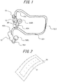
- An audio device is, for example, a hearing aid or a headphone and generally includes an audio unit 10, an organism sensor unit 500, and a support 60 for supporting the audio unit 10 and the organism sensor unit 500.
- the audio unit 10 includes a piezoelectric element 101 that curves and a panel 102 that vibrates when directly bent by the piezoelectric element 101.
- FIG. 2 is a diagram schematically illustrating a state of the panel 102 bent by the piezoelectric element 101.
- the panel 102 when directly bend by the piezoelectric element 101, vibrates and widely curves in a central area thereof in a manner protruding from both ends thereof.
- the audio unit 10 functions to provide a user with a human body vibration sound caused mainly by vibration. Depending on a size of the panel, an air conduction sound may be generated.
- the air conduction sound is a sound that is delivered to the user's auditory nerve when air vibration caused by vibration of a substance travels through the external ear canal and vibrates the ear drum.
- the human body vibration sound is a sound that is delivered to the user's auditory nerve via a part of the user's body (for example, the cartilage of the external ear) in contact with a vibrating substance.
- the human body vibration sound may contain a component that changes from the vibration to the air conduction inside the external ear canal.
- the harmonic components are provided together, regardless of the size of the panel 102 (for example, a rectangular shape of 3 cm in length and 1 cm in width or smaller), the sound becomes enough loud to be heard.
- the human body vibration sound contributes especially to articulation and thus is suitable for a person with geriatric defective hearing who has a difficulty in hearing a high pitch sound.
- the piezoelectric element 101 is an element that, upon application of an electric signal (a voltage), contracts or curves (bends) according to an electromechanical coupling factor of a material thereof.
- the piezoelectric element 101 is directly attached to the panel 102 via a double-sided tape.
- the piezoelectric element may be made of, for example, ceramics or crystal.
- the piezoelectric element 101 may be a unimorph, a bimorph, or a laminated piezoelectric element.
- the laminated piezoelectric element includes a laminated unimorph element in which the unimorphs are laminated (for example, approximately 16 to 100 layers thereof) or a laminated bimorph element in which the bimorphs are laminated (for example, approximately 16 to 48 layers thereof).
- the laminated piezoelectric element includes a plurality of dielectric layers made of, for example, PZT (lead zirconate titanate) and electrode layers disposed therebetween.
- PZT lead zirconate titanate
- the unimorph contracts, while the bimorph bends.
- the panel 102 is made of, for example, a hard material such as glass and sapphire, or a synthetic resin such as acryl and polycarbonate.
- the panel 102 is in a plate shape, and hereinafter the panel 102 is assumed as such.
- the panel is approximately 2 cm to 5 cm in length and 0.5 cm to 2 cm in width.
- the piezoelectric element 102 is directly attached to the panel 102 via the double-sided tape and the like.
- the microphone 20 collects a sound from a sound source, in particular, a sound that reaches near the user's helix. Since the microphone 20 is behind the helix and thus unlikely to collect a sound leaking from the external ear canal (i.e., unlikely to cause howling), the microphone 20 may easily reproduce a natural sound to the user.
- One microphone unit may be provided to the audio unit 10 on both a left side and a right side.
- One microphone may generate a signal to be shared by the audio units on the left side and the right side.
- the microphone is not necessary when an audio device does not need a function to collect and provide an ambient sound. It is a matter of course that the microphone may be used for an input of a telephone call. An exterior audio signal or an audio signal stored in an internal storage area needs to be input to a controller 30.
- FIG. 3 illustrates an example of a block diagram.
- the controller (IC) 30 carries out various control of the audio device 1.
- the controller 30 applies a predetermined electric signal (a voltage according to a sound signal) to the piezoelectric element 101.
- the controller 30 controls an A/D converter 31 to convert the sound signal collected by the microphone unit 20 into a digital signal.
- a signal processing unit 32 based on information on volume and sound quality provided from a volume adjustment interface unit 40 and also on information stored in a storage unit 50, outputs a digital signal for driving the audio unit 10.
- AD/A converter 33 converts the digital signal into an analogue electric signal, which is then amplified by a piezoelectric amplifier 34 and applied to the piezoelectric element 101.
- the voltage applied to the piezoelectric element 101 by the controller 30 may be higher than, for example, an applied voltage of an air conduction earphone speaker for delivering the air conduction sound.
- the panel 102 generates sufficient vibration and thus the human body vibration sound that is delivered via a part of the user's body.
- a level of the voltage to be applied may be appropriately adjusted according to fixing strength of the panel 102 or performance of the piezoelectric element 101.
- the panel 102 having the piezoelectric element 101 attached thereto deforms according to the contraction or bend of the piezoelectric element 101 and vibrates.
- the panel 102 curves due to the contraction or bend of the piezoelectric element 101.
- the panel 102 is directly bent by the piezoelectric element 101.
- “the panel 102 is directly bent by the piezoelectric element 101” is different from a phenomenon in which, as employed by a conventional panel speaker, inertial force of a piezoelectric actuator having the piezoelectric element 101 disposed inside a casing vibrates a particular area of the panel 102 and deforms the panel 102.
- the panel 102 is directly bent by the piezoelectric element 101 is a phenomenon in which the contraction or bend (curve) of the piezoelectric element 101 directly bends the panel 102 via a joining member.
- the panel 102 vibrates, when the panel 102 is in contact with the tragus, the human body vibration sound is generated via the tragus.
- the panel 102 vibrates having areas near both ends thereof functioning as a joint and the center thereof as the flat, in such a manner that an area near the center of the panel 102 abuts on the tragus and the antitragus. Thereby, the vibration of the panel 102 may be efficiently delivered to the tragus and the antitragus.
- the support 60 supports a housing unit 70. Further, the housing unit 70 supports the audio unit 10 at a position opposite to the ear.
- the support 60 supports the audio unit 10 and the organism sensor unit 500. Thereby, the audio unit 10 abuts on the ear.
- the audio unit 10 may abuts on, for example, the tragus or the antitragus. According to the present embodiment, hereinafter, it is assumed that the audio unit 10 abuts on the tragus.
- the organism sensor unit 500 is supported by a joint portion 604 extending from a bottom of the housing unit 70 at a position blocking the user's ear shell.
- the joint portion 604 is constituted by using a member such as a flat spring having appropriate elasticity.
- the joint portion 604 may be made of metal or resin, as a matter of course.
- a wire 510 is provided to supply an output signal from the organism sensor unit 500 and supply power to the organism sensor unit 500.
- the support 60 includes an arm portion 601 in a semicircular shape extending along the user's occipital region.
- the arm portion 601 may be designed to allow adjustment of pressure approximately between 0.1 N to 10 N when the housing unit 70 abuts on, for example, the tragus.
- the arm portion 601 may be made of a metal spring curved into a predetermined shape and coated with resin, or a resin spring and the like, and has appropriate elasticity.
- the support 60 includes a pair of ear hooking portions 602 formed continuously from the arm portion 601.
- the ear hooking portions 602, as illustrated in FIG. 8 curve to hang on a part of the user's helix.
- the ear hooking portions 602 may be integrally formed with the arm portion 601.
- Each of the ear hooking portions 602 of the support 60 is provided with the microphone 20. Although it is preferable that two microphones are provided for each of the left ear and the right ear, one microphone may be provided for either one of the ears.
- the support 60 at a distal end of the ear hooking portion 602, is provided with the support portion 603 for supporting the housing unit 70.
- the support portion 603 supports the housing unit 70 in such a manner that the panel 102 disposed on the housing unit 70 abuts on the user's ear.
- the housing unit 70 is supported by the support portion 603 of the support 60 and includes a substrate 702 and the like thereinside.
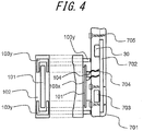
- the following is a detailed description of the housing unit 70 and the audio unit 10 with reference to FIG. 4 by way of example.
- FIG. 4 is a cross-sectional diagram of the audio unit 10 and the housing unit 70 viewed in a thickness direction.
- the audio unit 10 includes the piezoelectric element 101 and the panel 102.
- the piezoelectric element 101 is in a panel shape as illustrated in FIG. 4 .
- the piezoelectric element 101 is attached to the panel 102 via a joint member 103x.
- the joint member 103x is provided between a principal plane of the piezoelectric element 101 and a principal plane of the panel 102.
- the joint member 103x is preferably a non-thermosetting adhesive or the double-sided tape.
- the double-sided tape may be, for example, a cloth impregnated with adhesive resin.
- the principal plane of the panel 102 is in size 0.8 to 10 times larger than the principal plane of the piezoelectric element 101.
- the size of the principal plane of the panel 102 is within a range of 0.8 to 10 times of the size of the principal plane of the piezoelectric element 101, the panel 102 may deform according to the contraction or bend of the piezoelectric element 101 and, also, a sufficient area to come into contact with the user's ear may be ensured.
- the size of the panel is, for example, 0.8 to 5 times of the size of the piezoelectric element.
- the panel 102 on the principal plane on an ear side, may have a concave shape.
- the panel 102 may be more easily contact the tragus that is protruding, in comparison with the panel 102 with a flat principal plane. That is, the panel 102 having the concave shape is effective in preventing displacement thereof.
- a pair of double-sided tapes 103y are attached on a rear side of the panel 102 (on a side opposite to the housing unit 70). These double-sided tapes 103y attach the panel 102 to a principal plane of the housing unit 70. Thereby, the panel 102 is attached to the housing unit 70.
- the double-sided tape 103y is provided at either end of the piezoelectric element 101. Since the double-sided tape 103y is not provided to the piezoelectric element 101 at any other positions including the center area than each end of the piezoelectric element 101, sufficient vibration of the piezoelectric element 101 with low power consumption may be ensured at the center thereof. Note that, when the piezoelectric element 101 sufficiently strongly vibrates, the double-sided tape 103y may be provided in the entire area of the panel 102 in order to attach the panel 102 to the housing unit 70.
- the double-sided tape 103y is attached in a U-shape or a C-shape along three ends of the piezoelectric element 101, from a viewpoint of reinforcing the adhesion while efficiently using the small area of the panel 102. Thereby, the double-sided tape 103y is unlikely to inhibit the bend of the panel 102.
- a pair of solders 104 are formed, to which a wire 704 is joined connecting to the substrate 702 in the housing unit 70 described later.
- the housing unit 70 includes a housing 701, the substrate 702, a battery 703, the wire 704, and a screw 705. Further, the housing 70 includes the controller (IC) 30 built therein.
- the housing 701 is made of, for example, plastics.
- the housing 701 is obtained by molding a resin material such as polycarbonate resin and amine-based resin.
- a material in which synthetic resin having glass fiber weaved therein for example, Reny (registered trademark) produced by Mitsubishi Gas Chemical Company, Inc.
- the material of the housing 701 needs to be as light as possible so as ease the burden on the helix, as well as to be sufficiently strong against an impact of falling and the like. However, when the material is too light and thin, a resonance is easily generated, causing energy loss. Accordingly, a material and weight of the housing 701 is determined in consideration of both lightness and strength. That is, from a viewpoint of vibration, a material having rigidity as high as possible is preferably used. From this point of view, the housing 701 may be made of thick metal.
- the housing 701 is one casing made up of a pair of members bolted together using screws 705.
- the members are preferably bolted together, rather than being bonded together, so as to allow replacement of the battery 703.
- the substrate 702 inside the housing 701 is electrically connected to the controller 30 and the piezoelectric element 101 via the solders 104 and the wire 704. Also, the substrate is provided with the battery 703 mounted thereon.
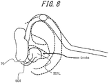
- FIG. 8 is a diagram illustrating a state in which the user is wearing the audio device 1 according to one embodiment on the ear.
- the audio unit 10 externally abuts on the ear near the user's tragus and antitragus and delivers the vibration thereto, thereby providing the sound to the user.
- the audio unit 10 externally abuts on the user's tragus. It is a matter of course that the audio unit 10 may abuts on either one of, or both of, the ears.
- the audio unit 10 applies a pressure of 0.1 N to 3 N to the user's ear.
- the audio unit 10 applies a pressure within a range of 0.1 N to 3 N, the vibration of the audio unit 10 is sufficiently delivered to the ear.
- the pressure is equal to or lower than 3 N, the audio device 1 hardly makes the user feel tired after wearing the audio device 1 for many hours and is capable of maintaining wearing comfort.
- the tragus being slightly flattened does not block the external ear canal and thus is less likely to cause an ear-stuffed feeling.
- FIG. 9 illustrates measured data of acoustic characteristics of the audio unit 10 on the right side of the audio device 1.
- FIG. 9 illustrates data of 12 samples and a mean value thereof.
- sufficiently good acoustic characteristics are shown in each frequency band from 200 Hz to 8 kHz.
- a high sound pressure was obtained, which is effective also for a hearing-impaired person who speaks a language other than Japanese, such as English and the like.
- the audio device 1 has a wide coverage of the frequency band and thus may be preferably used as the earphone.
- the audio device 1 illustrated in FIG. 6 employs a low-pass filter for gradually attenuating a signal at 8 kHz or over.
- the piezoelectric element 101 may vibrate in response to a sound in an ultrasonic frequency band such as, for example, 40 kHz. Therefore, the audio device 1 may also function as an audio device for generating various ultrasonic waves.
- FIG. 3 illustrates a block diagram of the organism sensor unit 500.
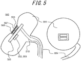
- the organism sensor unit 500 according to the present embodiment, as illustrated in FIG. 5 and FIG. 6 , by using organic sensors 501L and 501R (a light reception unit 508 and a light emission unit 507) mounted in a housing 504 to be inserted into the ear, measures, for example, a user's pulse.
- the light emission unit 507 and the light reception unit 508 of the organic sensors 501L and 501R are arranged in parallel having a light shielding wall therebetween inside the housing 504.
- a light transmission panel 505 is disposed on the organic sensors for a protective purpose, whereby the housing 504 is sealed.
- the light emission unit 507 uses a blue (a wavelength: 400 to 430 nm) or a green (the wavelength: 500 to 550 nm) LED or laser.
- the blue light and the green light with wavelengths described above are easily absorbed by hemoglobin. Therefore, an amount of the light absorbed increases in proportion to a volume of blood flow, and an output to the light reception unit 508 becomes weaker in proportion thereto.
- a red light (the wavelength: 630 to 650 nm) LED or the laser may be used. In this case, since the hemoglobin reflects an infrared light, an amount of the light reflected increases in proportion to the volume of blood flow, and the output to the light reception unit 508 becomes stronger in proportion thereto.
- a photodiode corresponding to the wavelength is used.
- red the wavelength: 1.31 ⁇ m or 1.55 ⁇ m
- red laser is used so as to detect a relative volume of blood flow from a phase difference of the frequency caused by a Doppler shift.
- the housing 504 includes the substrate 506 and the controller 502 therein.
- the controller 502 mounted on the substrate 506 may include a determination unit for controlling light emission timing of the light emission unit 507 to the light reception unit 508 as well as for determining an error or a noise signal based on a signal of the light reception unit 508, and also a calculation unit for calculating the pulse and the volume of blood flow. Sampling is carried out at intervals of 0.005 to 0.1 second.
- the determination unit determines that an error has occurred when detecting a high frequency that cannot be generated in the human body.
- the laser for emitting, for example, the red light (the wavelength: 1.31 ⁇ m or 1.55 ⁇ m) is used to detect the relative volume of blood flow from the phase difference of the frequency caused by the Doppler shift.
- the controller 502 provided inside the housing 504, similarly to the sensor for measuring the pulse, controls the light emission timing of the light emission unit 507 to the light reception unit 508 as well as for determining an error or the noise signal based the signal of the light reception unit 508, and the calculation unit for calculating the volume of blood flow. Sampling is carried out at intervals of 0.005 to 0.1 second.
- the organism sensor 501L and an organism sensor 501R may function as a pulse sensor and a body temperature measurement sensor 511, respectively. It is a matter of course that a combination of the blood flow sensor and the pulse sensor or a combination of the blood flow sensor and the body temperature sensor may be used.
- the body temperature measurement sensor 511 measures the body temperature by, for example, detecting the infrared light travelling from the external ear canal toward outside the ear.
- the housing 504 includes the substrate 506 and the controller 502 therein. The controller 502 mounted on the substrate 506 controls an operation of the light reception unit for measuring the body temperature and manages data of the body temperature.
- Biometric data from each of the organism sensors are stored in the storage unit 503.
- the storage unit 503 is provided separately from the storage unit 50 that is used for the audio function in FIG. 3 , the storage unit 50 may also function as the storage unit 503.
- the biometric data stored in the storage unit 503 may be externally provided as necessary via a communication unit 1001 or the like.
- the organism sensor unit 500 includes an insertion unit 509 to be inserted into the external ear canal, which is different from the embodiment illustrated in FIG. 5 and FIG. 6 . Therefore, the housing 504 is provided with an engaging unit 504' that is engaged with an engaged portion 509' provided to the insertion unit 509.
- the insertion unit 509 is made of rubber with Shore hardness of, for example, approximately 30 to 60. Alternatively, the insertion unit 509 may be made of a molded hard polyimide resin.
- the housing 504 may have a vent (an air hole) 512 so as to reduce the ear-stuffed feeling.
- FIG. 8 illustrates a diagram of an example of the wearing state of the audio device 1.
- the housing 504 of the organism sensor 500 is placed in such a manner as to face the concha inside the ear.
- the light emission unit 507 emits the light toward the concha. The light is unlikely to leak outside.
- a rear side of the housing 504 (outside the ear) abuts on a rear side of the tragus and a rear portion of the antitragus, whereby the housing 504 is held inside the ear.
- a front side of the housing 504 faces the concha (and may abut on the concha).
- a space surrounded by the concha and the front side of the housing 504, because of a peripheral portion of the housing 504, is unlikely to receive external light. Therefore, the external light is unlikely to reach the light reception unit 508, and reliability of the measurement of the sensor may be easily improved.
- the audio unit 10 abuts on the tragus and, by vibrating the internal wall of the external ear canal, may deliver the air conduction sound. At this time, when the audio unit 10 and the organism sensor 500 sandwich the tragus from inside and outside the ear, the delivery of the vibration is more likely to be ensured.
- the organization sensor unit 500 includes a combination of the body temperature sensor and the pulse sensor.
- the audio unit 10 may issue notification of a possibility of heat stroke.
- the communication unit 1001 may transmit, to a registered particular receiver, notification of that the measured person is having the heat stroke or various measured organism data (the pulse, the temperature, and the volume of blood flow).
- the registered particular receiver may be a user's doctor or nurse and the like.
- the communication unit 1001 may employ a conventionally known communication method such as, for example, one in accordance with LTE and the like or Wi-Fi. Although in FIG. 1 the communication unit 1001 is disposed on the rear side of the support 60, i.e., at a position opposite to the occipital region, the location of the communication unit 1001 is not limited thereto.
- the audio device 1 is the hearing aid, the audio device 1 is not limited thereto.
- the audio device 1 may be a music player, in which case the microphone 20 may be omitted.
- the audio device 1 may reproduce music based on music data stored in an internal memory thereof, or based on music data stored in an external server via the network. Further, the audio device 1 may store a synthesized voice or an alarm sound for warning about the heat stroke as described above by way of example.
Landscapes
- Health & Medical Sciences (AREA)
- Life Sciences & Earth Sciences (AREA)
- Engineering & Computer Science (AREA)
- Physics & Mathematics (AREA)
- Cardiology (AREA)
- General Health & Medical Sciences (AREA)
- Animal Behavior & Ethology (AREA)
- Veterinary Medicine (AREA)
- Public Health (AREA)
- Biophysics (AREA)
- Pathology (AREA)
- Biomedical Technology (AREA)
- Heart & Thoracic Surgery (AREA)
- Medical Informatics (AREA)
- Molecular Biology (AREA)
- Surgery (AREA)
- Physiology (AREA)
- Signal Processing (AREA)
- Acoustics & Sound (AREA)
- Otolaryngology (AREA)
- Hematology (AREA)
- Pulmonology (AREA)
- Manufacturing & Machinery (AREA)
- Measuring Pulse, Heart Rate, Blood Pressure Or Blood Flow (AREA)
- Neurosurgery (AREA)
- Measuring And Recording Apparatus For Diagnosis (AREA)
- Piezo-Electric Transducers For Audible Bands (AREA)
- Headphones And Earphones (AREA)
- Artificial Intelligence (AREA)
- Computer Vision & Pattern Recognition (AREA)
- Psychiatry (AREA)
- Computer Networks & Wireless Communication (AREA)
Claims (13)
- Dispositif audio configuré pour être utilisé par un utilisateur, comprenant :une unité audio (10) ;une unité de capteur d'organisme (500) configuré pour être insérée dans une oreille de l'utilisateur ;une unité de boîtier (70) comprenant l'unité audio (10) ; etune partie de joint (604),dans lequel dans un état où le dispositif audio est porté par l'utilisateur, la partie de joint (604) s'étend depuis le bas de l'unité de boîtier (70), et ladite partie de joint (604) supporte l'unité de capteur d'organisme (500) à une position obstruant le pavillon d'oreille de l'utilisateur,caractérisé en ce quel'unité audio (10) est configurée pour buter de manière externe sur l'oreille de l'utilisateur sans être insérée dans l'oreille de l'utilisateur ; etl'unité audio (10) comprend un élément piézoélectrique (101) qui est incurvé et un panneau (102) qui vibre lorsqu'il est directement courbé par l'élément piézoélectrique (101).
- Dispositif audio selon la revendication 1, le dispositif audio butant de manière externe sur un tragus ou un antitragus de l'utilisateur.
- Dispositif audio selon la revendication 1, dans lequel l'unité de capteur d'organisme mesure un pouls, un volume d'écoulement sanguin ou une température corporelle de l'utilisateur.
- Dispositif audio selon la revendication 1, dans lequel l'unité de capteur d'organisme est munie d'une paire de capteurs sur un côté oreille gauche et un côté oreille droite.
- Dispositif audio selon la revendication 1, dans lequel l'unité audio est munie d'une paire d'unités audio sur le côté oreille gauche et le côté oreille droite.
- Dispositif audio selon la revendication 1, dans lequel l'unité de capteur d'organisme est insérée dans une conque de l'utilisateur.
- Dispositif audio selon la revendication 6, dans lequel l'unité de capteur d'organisme est munie d'une unité d'émission de lumière et d'une unité de réception de lumière, et l'unité d'émission de lumière est configurée pour émettre la lumière vers la conque de l'utilisateur.
- Dispositif audio selon la revendication 4, dans lequel la paire de capteurs sur le côté oreille gauche et le côté oreille droite est configurée pour mesurer des données d'organisme différentes telles qu'un pouls, un volume d'écoulement sanguin et une température.
- Dispositif audio selon la revendication 8, comprenant en outre une unité de communication configurée pour transmettre de manière externe les données d'organisme.
- Dispositif audio selon la revendication 8, dans lequel, lorsqu'une possibilité d'un problème de santé de l'utilisateur est détectée à partir des données d'organisme, l'unité audio est configurée pour le notifier en conséquence.
- Dispositif audio selon la revendication 1, dans lequel l'unité audio et l'unité de capteur d'organisme prennent en sandwich un tragus de l'oreille de l'utilisateur.
- Dispositif audio selon la revendication 1, dans lequel l'unité de capteur d'organisme est munie d'une unité d'insertion à insérer dans un conduit auditif externe de l'utilisateur.
- Dispositif audio selon la revendication 1, dans lequel le capteur d'organisme est muni d'un évent destiné à permettre une communication d'un conduit auditif externe de l'utilisateur avec l'extérieur.
Applications Claiming Priority (1)
| Application Number | Priority Date | Filing Date | Title |
|---|---|---|---|
| JP2014182377 | 2014-09-08 |
Publications (2)
| Publication Number | Publication Date |
|---|---|
| EP2999233A1 EP2999233A1 (fr) | 2016-03-23 |
| EP2999233B1 true EP2999233B1 (fr) | 2020-02-12 |
Family
ID=53938188
Family Applications (1)
| Application Number | Title | Priority Date | Filing Date |
|---|---|---|---|
| EP15181659.2A Active EP2999233B1 (fr) | 2014-09-08 | 2015-08-20 | Dispositif audio |
Country Status (3)
| Country | Link |
|---|---|
| US (1) | US10335084B2 (fr) |
| EP (1) | EP2999233B1 (fr) |
| JP (1) | JP6219889B2 (fr) |
Families Citing this family (16)
| Publication number | Priority date | Publication date | Assignee | Title |
|---|---|---|---|---|
| JP6703456B2 (ja) * | 2016-08-02 | 2020-06-03 | 日本電信電話株式会社 | 判定装置の作動方法、判定装置およびウェアラブルセンサシステム |
| EP3334186B1 (fr) * | 2016-12-08 | 2021-03-03 | GN Hearing A/S | Système d'écoute et procédé de récupération des données de dispositif d'écoute |
| JP2020054409A (ja) * | 2017-02-07 | 2020-04-09 | アルプスアルパイン株式会社 | センサモジュールおよびその制御方法 |
| WO2019003811A1 (fr) | 2017-06-27 | 2019-01-03 | 京セラ株式会社 | Instrument électronique, serveur, structure de données, procédé de gestion de condition physique, et programme de gestion de condition physique |
| EP3437551B1 (fr) * | 2017-08-03 | 2019-07-31 | Natus Medical Incorporated | Appareil de mesure d'immittance acoustique à large bande |
| US10701470B2 (en) | 2017-09-07 | 2020-06-30 | Light Speed Aviation, Inc. | Circumaural headset or headphones with adjustable biometric sensor |
| US10764668B2 (en) | 2017-09-07 | 2020-09-01 | Lightspeed Aviation, Inc. | Sensor mount and circumaural headset or headphones with adjustable sensor |
| CN107948822A (zh) * | 2017-12-23 | 2018-04-20 | 广州市尊浪电器有限公司 | 一种智能感应音响 |
| CN111566726A (zh) * | 2017-12-28 | 2020-08-21 | 京瓷株式会社 | 电子设备、控制系统、控制方法和控制程序 |
| JP6927873B2 (ja) * | 2017-12-28 | 2021-09-01 | 京セラ株式会社 | 電子機器、推定システム、制御方法及び制御プログラム |
| US10602258B2 (en) * | 2018-05-30 | 2020-03-24 | Facebook Technologies, Llc | Manufacturing a cartilage conduction audio device |
| JP7141617B2 (ja) | 2018-07-10 | 2022-09-26 | Cyberdyne株式会社 | 生理状態評価装置 |
| JP2021136586A (ja) * | 2020-02-27 | 2021-09-13 | 英治 山田 | 補聴器及びイヤフォン |
| WO2022077242A1 (fr) * | 2020-10-13 | 2022-04-21 | Linksense Technology Co., Ltd. | Dispositif à porter sur soi pour détecter des signaux physiologiques et système et procédé pour l'utiliser |
| JP7568942B2 (ja) * | 2022-05-02 | 2024-10-17 | スターライト工業株式会社 | センサユニット |
| JP2025086003A (ja) * | 2023-11-27 | 2025-06-06 | ソニーグループ株式会社 | 情報処理装置、情報処理方法、およびプログラム |
Family Cites Families (30)
| Publication number | Priority date | Publication date | Assignee | Title |
|---|---|---|---|---|
| EP0051832B1 (fr) * | 1980-11-07 | 1985-02-27 | Hitachi, Ltd. | Transducteur piézoélectrique céramique |
| JPS58198329A (ja) * | 1982-05-15 | 1983-11-18 | 松下電工株式会社 | 脈拍計 |
| US5062432A (en) * | 1990-05-09 | 1991-11-05 | Labelle Industries, Inc. | Method and apparatus for monitoring personal core temperature |
| JP2882346B2 (ja) * | 1996-03-18 | 1999-04-12 | 日本電気株式会社 | 圧電式イヤホン |
| JPH09253062A (ja) * | 1996-03-22 | 1997-09-30 | Ikyo Kk | イヤホーン型脈拍センサ |
| JPH10117397A (ja) * | 1996-10-09 | 1998-05-06 | Ube Ind Ltd | 圧電スピーカ |
| US8482488B2 (en) | 2004-12-22 | 2013-07-09 | Oakley, Inc. | Data input management system for wearable electronically enabled interface |
| US6647368B2 (en) * | 2001-03-30 | 2003-11-11 | Think-A-Move, Ltd. | Sensor pair for detecting changes within a human ear and producing a signal corresponding to thought, movement, biological function and/or speech |
| US6808473B2 (en) * | 2001-04-19 | 2004-10-26 | Omron Corporation | Exercise promotion device, and exercise promotion method employing the same |
| CN101897582B (zh) * | 2003-10-09 | 2012-11-21 | 日本电信电话株式会社 | 生物体信息采集系统 |
| JP2005348193A (ja) | 2004-06-04 | 2005-12-15 | Nec Tokin Corp | 受話器 |
| JP4460414B2 (ja) * | 2004-10-06 | 2010-05-12 | 日本電信電話株式会社 | 血圧計 |
| JP2006212178A (ja) * | 2005-02-03 | 2006-08-17 | Nippon Telegr & Teleph Corp <Ntt> | 血圧計及び血圧判定方法 |
| JP2006245799A (ja) * | 2005-03-01 | 2006-09-14 | Nec Saitama Ltd | 電子機器、該電子機器における警報出力制御方法及び警報出力制御プログラム |
| JP4166764B2 (ja) | 2005-04-25 | 2008-10-15 | リオン株式会社 | 耳あな形補聴器のベント寸法決定方法 |
| JP4511437B2 (ja) * | 2005-09-09 | 2010-07-28 | Necトーキン株式会社 | 音響信号発生用圧電装置 |
| JP2007185348A (ja) * | 2006-01-13 | 2007-07-26 | Olympus Corp | 生体情報検出装置 |
| JP2008136556A (ja) * | 2006-11-30 | 2008-06-19 | Ibox:Kk | イヤホン装置 |
| US8323982B2 (en) | 2007-01-11 | 2012-12-04 | Valencell, Inc. | Photoelectrocatalytic fluid analyte sensors and methods of fabricating and using same |
| JP4910146B2 (ja) * | 2007-02-27 | 2012-04-04 | 国立大学法人九州工業大学 | ヘッドホン装置 |
| US8251903B2 (en) | 2007-10-25 | 2012-08-28 | Valencell, Inc. | Noninvasive physiological analysis using excitation-sensor modules and related devices and methods |
| WO2010006036A1 (fr) * | 2008-07-08 | 2010-01-14 | Andrew Tye Hunt | Revêtements antimicrobiens |
| US8189846B2 (en) * | 2008-09-05 | 2012-05-29 | Apple Inc. | Vented in-the-ear headphone |
| EP3357419A1 (fr) | 2009-02-25 | 2018-08-08 | Valencell, Inc. | Dispositifs de guidage de lumière et dispositifs de surveillance les incorporant |
| US8788002B2 (en) * | 2009-02-25 | 2014-07-22 | Valencell, Inc. | Light-guiding devices and monitoring devices incorporating same |
| US20100217100A1 (en) | 2009-02-25 | 2010-08-26 | Leboeuf Steven Francis | Methods and Apparatus for Measuring Physiological Conditions |
| US9750462B2 (en) | 2009-02-25 | 2017-09-05 | Valencell, Inc. | Monitoring apparatus and methods for measuring physiological and/or environmental conditions |
| KR101136607B1 (ko) * | 2009-10-07 | 2012-04-18 | 삼성전자주식회사 | 생체정보 측정 장치가 구비된 이어폰 장치 |
| JP2013255012A (ja) * | 2012-06-05 | 2013-12-19 | Nikon Corp | 頭部保持部材、及び頭部装着型情報出力装置 |
| JP6100730B2 (ja) | 2014-04-22 | 2017-03-22 | 京セラ株式会社 | イヤホン |
-
2015
- 2015-07-17 JP JP2015142926A patent/JP6219889B2/ja active Active
- 2015-08-19 US US14/830,472 patent/US10335084B2/en active Active
- 2015-08-20 EP EP15181659.2A patent/EP2999233B1/fr active Active
Non-Patent Citations (1)
| Title |
|---|
| None * |
Also Published As
| Publication number | Publication date |
|---|---|
| US20160066851A1 (en) | 2016-03-10 |
| EP2999233A1 (fr) | 2016-03-23 |
| JP6219889B2 (ja) | 2017-10-25 |
| JP2016055155A (ja) | 2016-04-21 |
| US10335084B2 (en) | 2019-07-02 |
Similar Documents
| Publication | Publication Date | Title |
|---|---|---|
| EP2999233B1 (fr) | Dispositif audio | |
| US9967643B2 (en) | Earphone | |
| US9622000B2 (en) | Audio device | |
| US9686622B2 (en) | Acoustic reproduction device and sound-collecting acoustic reproduction device | |
| CN110177326B (zh) | 超声接近传感器以及相关系统和方法 | |
| US20110319021A1 (en) | Intra-oral tissue conduction microphone | |
| US9872113B2 (en) | Measurement device and measurement system | |
| CN104684485A (zh) | 带噪声振动控制的生物声学传感器 | |
| US9591414B2 (en) | Acoustic device | |
| JP2016072798A (ja) | 音声振動出力装置 | |
| EP2991377B1 (fr) | Appareil acoustique | |
| US9578406B2 (en) | Acoustic device | |
| CN215067583U (zh) | 一种红外听诊眼镜装置 | |
| CN113156669A (zh) | 一种红外听诊眼镜装置及其制作方法 |
Legal Events
| Date | Code | Title | Description |
|---|---|---|---|
| PUAI | Public reference made under article 153(3) epc to a published international application that has entered the european phase |
Free format text: ORIGINAL CODE: 0009012 |
|
| 17P | Request for examination filed |
Effective date: 20150820 |
|
| AK | Designated contracting states |
Kind code of ref document: A1 Designated state(s): AL AT BE BG CH CY CZ DE DK EE ES FI FR GB GR HR HU IE IS IT LI LT LU LV MC MK MT NL NO PL PT RO RS SE SI SK SM TR |
|
| AX | Request for extension of the european patent |
Extension state: BA ME |
|
| RBV | Designated contracting states (corrected) |
Designated state(s): AL AT BE BG CH CY CZ DE DK EE ES FI FR GB GR HR HU IE IS IT LI LT LU LV MC MK MT NL NO PL PT RO RS SE SI SK SM TR |
|
| STAA | Information on the status of an ep patent application or granted ep patent |
Free format text: STATUS: EXAMINATION IS IN PROGRESS |
|
| 17Q | First examination report despatched |
Effective date: 20180801 |
|
| RIC1 | Information provided on ipc code assigned before grant |
Ipc: H04R 5/033 20060101ALN20190814BHEP Ipc: H04R 1/10 20060101AFI20190814BHEP Ipc: A61B 5/024 20060101ALI20190814BHEP Ipc: H04R 17/00 20060101ALI20190814BHEP Ipc: A61B 5/0205 20060101ALI20190814BHEP Ipc: A61B 5/0295 20060101ALI20190814BHEP Ipc: A61B 5/00 20060101ALI20190814BHEP |
|
| GRAP | Despatch of communication of intention to grant a patent |
Free format text: ORIGINAL CODE: EPIDOSNIGR1 |
|
| STAA | Information on the status of an ep patent application or granted ep patent |
Free format text: STATUS: GRANT OF PATENT IS INTENDED |
|
| INTG | Intention to grant announced |
Effective date: 20191009 |
|
| GRAS | Grant fee paid |
Free format text: ORIGINAL CODE: EPIDOSNIGR3 |
|
| GRAA | (expected) grant |
Free format text: ORIGINAL CODE: 0009210 |
|
| STAA | Information on the status of an ep patent application or granted ep patent |
Free format text: STATUS: THE PATENT HAS BEEN GRANTED |
|
| AK | Designated contracting states |
Kind code of ref document: B1 Designated state(s): AL AT BE BG CH CY CZ DE DK EE ES FI FR GB GR HR HU IE IS IT LI LT LU LV MC MK MT NL NO PL PT RO RS SE SI SK SM TR |
|
| REG | Reference to a national code |
Ref country code: GB Ref legal event code: FG4D |
|
| REG | Reference to a national code |
Ref country code: CH Ref legal event code: EP |
|
| REG | Reference to a national code |
Ref country code: AT Ref legal event code: REF Ref document number: 1233706 Country of ref document: AT Kind code of ref document: T Effective date: 20200215 |
|
| REG | Reference to a national code |
Ref country code: IE Ref legal event code: FG4D |
|
| REG | Reference to a national code |
Ref country code: DE Ref legal event code: R096 Ref document number: 602015046676 Country of ref document: DE |
|
| PG25 | Lapsed in a contracting state [announced via postgrant information from national office to epo] |
Ref country code: FI Free format text: LAPSE BECAUSE OF FAILURE TO SUBMIT A TRANSLATION OF THE DESCRIPTION OR TO PAY THE FEE WITHIN THE PRESCRIBED TIME-LIMIT Effective date: 20200212 Ref country code: RS Free format text: LAPSE BECAUSE OF FAILURE TO SUBMIT A TRANSLATION OF THE DESCRIPTION OR TO PAY THE FEE WITHIN THE PRESCRIBED TIME-LIMIT Effective date: 20200212 Ref country code: NO Free format text: LAPSE BECAUSE OF FAILURE TO SUBMIT A TRANSLATION OF THE DESCRIPTION OR TO PAY THE FEE WITHIN THE PRESCRIBED TIME-LIMIT Effective date: 20200512 |
|
| REG | Reference to a national code |
Ref country code: LT Ref legal event code: MG4D |
|
| REG | Reference to a national code |
Ref country code: NL Ref legal event code: MP Effective date: 20200212 |
|
| PG25 | Lapsed in a contracting state [announced via postgrant information from national office to epo] |
Ref country code: IS Free format text: LAPSE BECAUSE OF FAILURE TO SUBMIT A TRANSLATION OF THE DESCRIPTION OR TO PAY THE FEE WITHIN THE PRESCRIBED TIME-LIMIT Effective date: 20200612 Ref country code: BG Free format text: LAPSE BECAUSE OF FAILURE TO SUBMIT A TRANSLATION OF THE DESCRIPTION OR TO PAY THE FEE WITHIN THE PRESCRIBED TIME-LIMIT Effective date: 20200512 Ref country code: HR Free format text: LAPSE BECAUSE OF FAILURE TO SUBMIT A TRANSLATION OF THE DESCRIPTION OR TO PAY THE FEE WITHIN THE PRESCRIBED TIME-LIMIT Effective date: 20200212 Ref country code: GR Free format text: LAPSE BECAUSE OF FAILURE TO SUBMIT A TRANSLATION OF THE DESCRIPTION OR TO PAY THE FEE WITHIN THE PRESCRIBED TIME-LIMIT Effective date: 20200513 Ref country code: SE Free format text: LAPSE BECAUSE OF FAILURE TO SUBMIT A TRANSLATION OF THE DESCRIPTION OR TO PAY THE FEE WITHIN THE PRESCRIBED TIME-LIMIT Effective date: 20200212 Ref country code: LV Free format text: LAPSE BECAUSE OF FAILURE TO SUBMIT A TRANSLATION OF THE DESCRIPTION OR TO PAY THE FEE WITHIN THE PRESCRIBED TIME-LIMIT Effective date: 20200212 |
|
| PG25 | Lapsed in a contracting state [announced via postgrant information from national office to epo] |
Ref country code: NL Free format text: LAPSE BECAUSE OF FAILURE TO SUBMIT A TRANSLATION OF THE DESCRIPTION OR TO PAY THE FEE WITHIN THE PRESCRIBED TIME-LIMIT Effective date: 20200212 |
|
| PG25 | Lapsed in a contracting state [announced via postgrant information from national office to epo] |
Ref country code: LT Free format text: LAPSE BECAUSE OF FAILURE TO SUBMIT A TRANSLATION OF THE DESCRIPTION OR TO PAY THE FEE WITHIN THE PRESCRIBED TIME-LIMIT Effective date: 20200212 Ref country code: EE Free format text: LAPSE BECAUSE OF FAILURE TO SUBMIT A TRANSLATION OF THE DESCRIPTION OR TO PAY THE FEE WITHIN THE PRESCRIBED TIME-LIMIT Effective date: 20200212 Ref country code: PT Free format text: LAPSE BECAUSE OF FAILURE TO SUBMIT A TRANSLATION OF THE DESCRIPTION OR TO PAY THE FEE WITHIN THE PRESCRIBED TIME-LIMIT Effective date: 20200705 Ref country code: SM Free format text: LAPSE BECAUSE OF FAILURE TO SUBMIT A TRANSLATION OF THE DESCRIPTION OR TO PAY THE FEE WITHIN THE PRESCRIBED TIME-LIMIT Effective date: 20200212 Ref country code: DK Free format text: LAPSE BECAUSE OF FAILURE TO SUBMIT A TRANSLATION OF THE DESCRIPTION OR TO PAY THE FEE WITHIN THE PRESCRIBED TIME-LIMIT Effective date: 20200212 Ref country code: SK Free format text: LAPSE BECAUSE OF FAILURE TO SUBMIT A TRANSLATION OF THE DESCRIPTION OR TO PAY THE FEE WITHIN THE PRESCRIBED TIME-LIMIT Effective date: 20200212 Ref country code: CZ Free format text: LAPSE BECAUSE OF FAILURE TO SUBMIT A TRANSLATION OF THE DESCRIPTION OR TO PAY THE FEE WITHIN THE PRESCRIBED TIME-LIMIT Effective date: 20200212 Ref country code: ES Free format text: LAPSE BECAUSE OF FAILURE TO SUBMIT A TRANSLATION OF THE DESCRIPTION OR TO PAY THE FEE WITHIN THE PRESCRIBED TIME-LIMIT Effective date: 20200212 Ref country code: RO Free format text: LAPSE BECAUSE OF FAILURE TO SUBMIT A TRANSLATION OF THE DESCRIPTION OR TO PAY THE FEE WITHIN THE PRESCRIBED TIME-LIMIT Effective date: 20200212 |
|
| REG | Reference to a national code |
Ref country code: DE Ref legal event code: R097 Ref document number: 602015046676 Country of ref document: DE |
|
| REG | Reference to a national code |
Ref country code: AT Ref legal event code: MK05 Ref document number: 1233706 Country of ref document: AT Kind code of ref document: T Effective date: 20200212 |
|
| PLBE | No opposition filed within time limit |
Free format text: ORIGINAL CODE: 0009261 |
|
| STAA | Information on the status of an ep patent application or granted ep patent |
Free format text: STATUS: NO OPPOSITION FILED WITHIN TIME LIMIT |
|
| 26N | No opposition filed |
Effective date: 20201113 |
|
| PG25 | Lapsed in a contracting state [announced via postgrant information from national office to epo] |
Ref country code: IT Free format text: LAPSE BECAUSE OF FAILURE TO SUBMIT A TRANSLATION OF THE DESCRIPTION OR TO PAY THE FEE WITHIN THE PRESCRIBED TIME-LIMIT Effective date: 20200212 Ref country code: AT Free format text: LAPSE BECAUSE OF FAILURE TO SUBMIT A TRANSLATION OF THE DESCRIPTION OR TO PAY THE FEE WITHIN THE PRESCRIBED TIME-LIMIT Effective date: 20200212 |
|
| PG25 | Lapsed in a contracting state [announced via postgrant information from national office to epo] |
Ref country code: SI Free format text: LAPSE BECAUSE OF FAILURE TO SUBMIT A TRANSLATION OF THE DESCRIPTION OR TO PAY THE FEE WITHIN THE PRESCRIBED TIME-LIMIT Effective date: 20200212 Ref country code: PL Free format text: LAPSE BECAUSE OF FAILURE TO SUBMIT A TRANSLATION OF THE DESCRIPTION OR TO PAY THE FEE WITHIN THE PRESCRIBED TIME-LIMIT Effective date: 20200212 |
|
| PG25 | Lapsed in a contracting state [announced via postgrant information from national office to epo] |
Ref country code: MC Free format text: LAPSE BECAUSE OF FAILURE TO SUBMIT A TRANSLATION OF THE DESCRIPTION OR TO PAY THE FEE WITHIN THE PRESCRIBED TIME-LIMIT Effective date: 20200212 |
|
| REG | Reference to a national code |
Ref country code: CH Ref legal event code: PL |
|
| PG25 | Lapsed in a contracting state [announced via postgrant information from national office to epo] |
Ref country code: CH Free format text: LAPSE BECAUSE OF NON-PAYMENT OF DUE FEES Effective date: 20200831 Ref country code: LI Free format text: LAPSE BECAUSE OF NON-PAYMENT OF DUE FEES Effective date: 20200831 Ref country code: LU Free format text: LAPSE BECAUSE OF NON-PAYMENT OF DUE FEES Effective date: 20200820 |
|
| REG | Reference to a national code |
Ref country code: BE Ref legal event code: MM Effective date: 20200831 |
|
| PG25 | Lapsed in a contracting state [announced via postgrant information from national office to epo] |
Ref country code: IE Free format text: LAPSE BECAUSE OF NON-PAYMENT OF DUE FEES Effective date: 20200820 Ref country code: BE Free format text: LAPSE BECAUSE OF NON-PAYMENT OF DUE FEES Effective date: 20200831 |
|
| PG25 | Lapsed in a contracting state [announced via postgrant information from national office to epo] |
Ref country code: TR Free format text: LAPSE BECAUSE OF FAILURE TO SUBMIT A TRANSLATION OF THE DESCRIPTION OR TO PAY THE FEE WITHIN THE PRESCRIBED TIME-LIMIT Effective date: 20200212 Ref country code: MT Free format text: LAPSE BECAUSE OF FAILURE TO SUBMIT A TRANSLATION OF THE DESCRIPTION OR TO PAY THE FEE WITHIN THE PRESCRIBED TIME-LIMIT Effective date: 20200212 Ref country code: CY Free format text: LAPSE BECAUSE OF FAILURE TO SUBMIT A TRANSLATION OF THE DESCRIPTION OR TO PAY THE FEE WITHIN THE PRESCRIBED TIME-LIMIT Effective date: 20200212 |
|
| PG25 | Lapsed in a contracting state [announced via postgrant information from national office to epo] |
Ref country code: MK Free format text: LAPSE BECAUSE OF FAILURE TO SUBMIT A TRANSLATION OF THE DESCRIPTION OR TO PAY THE FEE WITHIN THE PRESCRIBED TIME-LIMIT Effective date: 20200212 Ref country code: AL Free format text: LAPSE BECAUSE OF FAILURE TO SUBMIT A TRANSLATION OF THE DESCRIPTION OR TO PAY THE FEE WITHIN THE PRESCRIBED TIME-LIMIT Effective date: 20200212 |
|
| P01 | Opt-out of the competence of the unified patent court (upc) registered |
Effective date: 20230508 |
|
| PGFP | Annual fee paid to national office [announced via postgrant information from national office to epo] |
Ref country code: GB Payment date: 20240627 Year of fee payment: 10 |
|
| PGFP | Annual fee paid to national office [announced via postgrant information from national office to epo] |
Ref country code: DE Payment date: 20240702 Year of fee payment: 10 |
|
| PGFP | Annual fee paid to national office [announced via postgrant information from national office to epo] |
Ref country code: FR Payment date: 20240702 Year of fee payment: 10 |
|
| REG | Reference to a national code |
Ref country code: DE Ref legal event code: R119 Ref document number: 602015046676 Country of ref document: DE |