EP2999633B1 - Aseptischer füllstoff für fliessfähige produkte - Google Patents
Aseptischer füllstoff für fliessfähige produkte Download PDFInfo
- Publication number
- EP2999633B1 EP2999633B1 EP14733011.2A EP14733011A EP2999633B1 EP 2999633 B1 EP2999633 B1 EP 2999633B1 EP 14733011 A EP14733011 A EP 14733011A EP 2999633 B1 EP2999633 B1 EP 2999633B1
- Authority
- EP
- European Patent Office
- Prior art keywords
- fitment
- chamber
- collar
- bag
- filler
- Prior art date
- Legal status (The legal status is an assumption and is not a legal conclusion. Google has not performed a legal analysis and makes no representation as to the accuracy of the status listed.)
- Active
Links
Images








Classifications
-
- B—PERFORMING OPERATIONS; TRANSPORTING
- B65—CONVEYING; PACKING; STORING; HANDLING THIN OR FILAMENTARY MATERIAL
- B65B—MACHINES, APPARATUS OR DEVICES FOR, OR METHODS OF, PACKAGING ARTICLES OR MATERIALS; UNPACKING
- B65B55/00—Preserving, protecting or purifying packages or package contents in association with packaging
- B65B55/02—Sterilising, e.g. of complete packages
- B65B55/022—Sterilising, e.g. of complete packages of flexible containers having a filling and dispensing spout, e.g. containers of the "bag-in-box"-type
-
- B—PERFORMING OPERATIONS; TRANSPORTING
- B65—CONVEYING; PACKING; STORING; HANDLING THIN OR FILAMENTARY MATERIAL
- B65B—MACHINES, APPARATUS OR DEVICES FOR, OR METHODS OF, PACKAGING ARTICLES OR MATERIALS; UNPACKING
- B65B3/00—Packaging plastic material, semiliquids, liquids or mixed solids and liquids, in individual containers or receptacles, e.g. bags, sacks, boxes, cartons, cans, or jars
- B65B3/04—Methods of, or means for, filling the material into the containers or receptacles
- B65B3/045—Methods of, or means for, filling the material into the containers or receptacles for filling flexible containers having a filling and dispensing spout, e.g. containers of the "bag-in-box"-type
-
- B—PERFORMING OPERATIONS; TRANSPORTING
- B65—CONVEYING; PACKING; STORING; HANDLING THIN OR FILAMENTARY MATERIAL
- B65B—MACHINES, APPARATUS OR DEVICES FOR, OR METHODS OF, PACKAGING ARTICLES OR MATERIALS; UNPACKING
- B65B31/00—Packaging articles or materials under special atmospheric or gaseous conditions; Adding propellants to aerosol containers
- B65B31/02—Filling, closing, or filling and closing, containers or wrappers in chambers maintained under vacuum or superatmospheric pressure or containing a special atmosphere, e.g. of inert gas
- B65B31/024—Filling, closing, or filling and closing, containers or wrappers in chambers maintained under vacuum or superatmospheric pressure or containing a special atmosphere, e.g. of inert gas specially adapted for wrappers or bags
-
- B—PERFORMING OPERATIONS; TRANSPORTING
- B65—CONVEYING; PACKING; STORING; HANDLING THIN OR FILAMENTARY MATERIAL
- B65B—MACHINES, APPARATUS OR DEVICES FOR, OR METHODS OF, PACKAGING ARTICLES OR MATERIALS; UNPACKING
- B65B39/00—Nozzles, funnels or guides for introducing articles or materials into containers or wrappers
- B65B39/001—Nozzles, funnels or guides for introducing articles or materials into containers or wrappers with flow cut-off means, e.g. valves
- B65B39/004—Nozzles, funnels or guides for introducing articles or materials into containers or wrappers with flow cut-off means, e.g. valves moving linearly
-
- B—PERFORMING OPERATIONS; TRANSPORTING
- B65—CONVEYING; PACKING; STORING; HANDLING THIN OR FILAMENTARY MATERIAL
- B65B—MACHINES, APPARATUS OR DEVICES FOR, OR METHODS OF, PACKAGING ARTICLES OR MATERIALS; UNPACKING
- B65B39/00—Nozzles, funnels or guides for introducing articles or materials into containers or wrappers
- B65B39/06—Nozzles, funnels or guides for introducing articles or materials into containers or wrappers adapted to support containers or wrappers
- B65B39/08—Nozzles, funnels or guides for introducing articles or materials into containers or wrappers adapted to support containers or wrappers by means of clamps
- B65B39/10—Nozzles, funnels or guides for introducing articles or materials into containers or wrappers adapted to support containers or wrappers by means of clamps operating automatically
-
- B—PERFORMING OPERATIONS; TRANSPORTING
- B65—CONVEYING; PACKING; STORING; HANDLING THIN OR FILAMENTARY MATERIAL
- B65B—MACHINES, APPARATUS OR DEVICES FOR, OR METHODS OF, PACKAGING ARTICLES OR MATERIALS; UNPACKING
- B65B39/00—Nozzles, funnels or guides for introducing articles or materials into containers or wrappers
- B65B39/12—Nozzles, funnels or guides for introducing articles or materials into containers or wrappers movable towards or away from container or wrapper during filling or depositing
-
- B—PERFORMING OPERATIONS; TRANSPORTING
- B65—CONVEYING; PACKING; STORING; HANDLING THIN OR FILAMENTARY MATERIAL
- B65B—MACHINES, APPARATUS OR DEVICES FOR, OR METHODS OF, PACKAGING ARTICLES OR MATERIALS; UNPACKING
- B65B55/00—Preserving, protecting or purifying packages or package contents in association with packaging
- B65B55/02—Sterilising, e.g. of complete packages
- B65B55/027—Packaging in aseptic chambers
-
- B—PERFORMING OPERATIONS; TRANSPORTING
- B65—CONVEYING; PACKING; STORING; HANDLING THIN OR FILAMENTARY MATERIAL
- B65B—MACHINES, APPARATUS OR DEVICES FOR, OR METHODS OF, PACKAGING ARTICLES OR MATERIALS; UNPACKING
- B65B55/00—Preserving, protecting or purifying packages or package contents in association with packaging
- B65B55/02—Sterilising, e.g. of complete packages
- B65B55/04—Sterilising wrappers or receptacles prior to, or during, packaging
- B65B55/10—Sterilising wrappers or receptacles prior to, or during, packaging by liquids or gases
-
- B—PERFORMING OPERATIONS; TRANSPORTING
- B65—CONVEYING; PACKING; STORING; HANDLING THIN OR FILAMENTARY MATERIAL
- B65B—MACHINES, APPARATUS OR DEVICES FOR, OR METHODS OF, PACKAGING ARTICLES OR MATERIALS; UNPACKING
- B65B57/00—Automatic control, checking, warning, or safety devices
-
- B—PERFORMING OPERATIONS; TRANSPORTING
- B65—CONVEYING; PACKING; STORING; HANDLING THIN OR FILAMENTARY MATERIAL
- B65B—MACHINES, APPARATUS OR DEVICES FOR, OR METHODS OF, PACKAGING ARTICLES OR MATERIALS; UNPACKING
- B65B7/00—Closing containers or receptacles after filling
- B65B7/02—Closing containers or receptacles deformed by, or taking-up shape, of, contents, e.g. bags, sacks
Definitions
- the present invention pertains to systems for aseptically packaging products in flexible containers or bags, and more particularly to aseptically filling flexible bags or containers fitted with standard fitments with various products, including food products, and in particular low acid content, flowable food products.
- flexible bags with standard fitments are positioned in a fill chamber to receive the food product routed to the fill chamber.
- the fill chamber is maintained in an overpressure condition to meet government regulatory requirements.
- the overpressure is designed to keep contaminants from entering the fill chamber.
- the overpressure is achieved through the use of sterile gas with chemicals designed to maintain the sterility of the fill chamber.
- the pressure of the fill chamber may dramatically decrease due to the volume of the empty bag.
- proof of positive pressure within the fill chamber is needed, and this is typically sought to be met by controlling and monitoring the flow of the sterile gas into the chamber.
- the fitment may be closed off by a center membrane which keeps the overpressure gas in the fill chamber from entering the bag when the cap of the fitment is first removed.
- the fill tube is designed with a cutting nozzle that must cut through the membrane at the time of filling the bag. This is said to keep the interior of the bag from being exposed to the gas and/or chemicals used to maintain the overpressure condition in the fill chamber.
- the present disclosure seeks to provide a system for aseptically filling flexible containers or bags employing standard fitments while maintaining a positive pressure in the fill chamber without the need for sterile gas and chemicals, but rather through the use of only steam.
- EP1067052 discloses an apparatus for filling a container such as a plastic bag with product.
- the apparatus comprises a fill valve and a chamber formed as an integral unit, in which during a filling operation a container with a cap is in place is offered up to and placed in the bag by gripping devices or jaws, the cap is removed by a capper mechanism the bag is filled with product, and the cap is replaced, all the flow paths and surfaces being sterilised by steam during the filling operation.
- EP0115963 discloses a device for filling a container through a sprout.
- the container includes a sterile chamber having a wall opening therethrough for inserting the sprout into the chamber.
- a cover inside the chamber is positioned over a base plate which encloses the wall opening to prevent the escape of sterile gas from the chamber when the sprout is being inserted into and removed from the wall opening.
- a pair of jaws fit around the sprout when the sprout is in the opening to hold the sprout in position for filling and to prevent contamination of the sterile chamber during the filling operation.
- An aseptic filler apparatus operates in a fill cycle to fill flexible bags with food products.
- a flexible bag is fitted with a fitment composed of a collar that is in food flow communication with the bag, as well as a removable cap engageable with the collar.
- the filler apparatus includes an enclosed filler chamber and a filler head disposed in the filler chamber to direct food products into the bag through the fitment.
- the apparatus also includes a fitment chamber in communication with the filler chamber, with the fitment chamber being substantially smaller in volume than the volume of the filler chamber.
- the apparatus in addition includes a holder assembly to hold the fitment within the fitment chamber, and includes a fitment plug assembly that is moveable between an actuated position to bear against the fitment collar to block food flow communication between the fitment collar and the bag during desired portions of the fill cycle, and a retracted position wherein the fitment plug is spaced away from the fitment collar to not hinder food flow communication between the fitment collar and the interior of the bag.
- the fitment plug assembly is positioned externally of the fitment bag. Further, when the fitment plug assembly is in actuated position, a portion of the bag is interposed between the fitment collar and the fitment plug. In this manner, a positive seal is achieved between the fitment plug and the adjacent end of the fitment collar.
- the fitment plug assembly includes a fitment plug shaped to close off the fitment collar when the fitment plug assembly is in actuated position, and an actuator assembly for moving the fitment plug between the actuated position and the retracted position of the fitment plug assembly.
- the actuator assembly includes a pivot arm for supporting the fitment plug and an actuator for moving the pivot arm between the actuated position of the fitment plug assembly and the retracted position of the fitment plug assembly.
- the disclosed filler apparatus also includes a fitment cap removal and replacement apparatus.
- Such apparatus is engageable with the fitment cap to remove the fitment cap from the fitment collar, and thereby provide access to the fitment collar during the filling of the bag by the filler head. The apparatus thereafter replaces the fitment cap into engagement with the fitment collar.
- steam from a steam source is directed to the fitment chamber for sterilizing the fitment
- a steam removal system is provided for directing the steam from the fitment chamber.
- the present disclosure also provides a method for filling a flexible bag with flowable food products at a filler station, wherein the filler station includes a filler head connectable to a source of flowable food product.
- the bag to be filled is flexible and is fitted with a fitment composed of a collar in food flow communication with the interior of the bag, and a cap for closing the collar.
- the method includes:
- the aseptic filling method includes applying a barrier against the fitment collar when closing off food flow communication between the fitment collar and the flexible bag.
- the barrier is located exterior of the bag.
- the barrier includes a fitment plug which can be placed against the fitment collar at the intersection of the fitment collar and the bag.
- the fitment plug is moveable between an engaged position when the fitment plug is disposed against the fitment collar, and a retracted position wherein the fitment plug is positioned away from the fitment collar.
- steam is applied to the fitment chamber to sterilize the fitment prior to placing the filler head in food flow communication with the fitment collar.
- references to food products and flowable food products are meant to include all manner of food products, including liquid, flowable and solid food products and mixtures thereof, such as soups, sauces, purees, fruits, vegetables, nuts, etc., as well as beverages, juices, and other drinks.
- a filler apparatus 30 is illustrated for filling liquid or otherwise flowable food product into a flexible bag 400 under sterile (aseptic) conditions.
- the bag 400 includes a fitment (also referred to as "fitment closure") 402, composed of a fitment or fill collar or neck 408 closed by a cap 404.
- the fill collar 408 is attached to the bag 400 at the end of the collar opposite to the cap.
- the collar may include flanges 410, 412, 414, extending around and outwardly of the collar to define circular grooves such as groove 406 that extends around the collar 408.
- the bag itself is composed of a tough, flexible, single- or multi-layer material such as for example, polyethylene, nylon, aluminum foil and metalized polyester.
- the bags can be of a wide range of sizes, from as small as 11 liters and up to over 1100 liters, or more and beyond.
- the collar 408 may be attached to the bag 400 by numerous different constructions as is known in the art.
- the cap 404 can also be of various constructions, including having a top portion 416 that overlaps a cylindrical portion 418. The cylindrical portion may be sized to closely fit within the inside and/or outside of the neck or collar 408.
- Standard or common fitments are in use with flexible bags.
- the filler spouts are designed to accommodate such standard fitments.
- the present filler apparatus can be adapted to be used with nonstandard or unique fitments also.
- the filler station or apparatus 30 in basic form includes a frame structure 50 that defines a filler chamber 60, maintained in an overpressure condition by a subtle gas, and preferably by steam.
- a filler head assembly 100 is extendible downwardly and retractable upwardly within the filler chamber. When extended downwardly, the filler head assembly 100 directs liquid food product to the flexible bag 400.
- the fill/fitment collar 408 is held stationary within a fitment chamber 200, located beneath the filler chamber 60 by a fitment holder assembly 350.
- the apparatus 30 also includes a fitment top or cap removal and replacement apparatus 450 to remove the fitment cap 404 from the fitment so that the bag can be filled, and then to replace the cap after the bag has been filled.
- Filler apparatus 30 in addition includes a plug assembly 300 for closing off the bottom of the filler chamber from the fitment chamber when the filler head is not being used to fill the bag 400.
- the filler apparatus 30 further includes an actuatable fitment plug assembly 500 that may be placed against the bottom of the fitment collar to prevent steam or other gasses or liquids from the filler chamber to enter the bag 400 when undesirable to do so, and also to maintain an overpressure condition in the filler chamber when the cap 404 is removed from the collar 408. Otherwise, when the cap 404 is removed from the fitment collar 408, the filler chamber would be placed in communication with the entire volume of the empty bag, thereby reducing the pressure in the filler chamber to an unacceptable level, which can result in contamination entering the fill chamber. If the pressure is maintained within the fill chamber, then contamination will be prevented from entering the fill chamber.
- an actuatable fitment plug assembly 500 that may be placed against the bottom of the fitment collar to prevent steam or other gasses or liquids from the filler chamber to enter the bag 400 when undesirable to do so, and also to maintain an overpressure condition in the filler chamber when the cap 404 is removed from the collar 408. Otherwise, when the cap 404 is removed from the fitment collar 408, the fill
- the frame structure 50 of the filler apparatus is composed in part of a plurality of upright posts 52 spanning between a top plate structure 54 and a bottom plate structure 56.
- the frame structure 50 may be carried by a support structure, not shown.
- the bottom plate structure 56 forms the top of the filler chamber 60.
- the filler chamber 60 is also formed by vertical side walls 62 and a floor plate structure 64 that engages the lower edges of the side walls 62.
- the filler chamber 60 is pressurized with a gas, preferably steam, thereby to prevent contaminants from entering the fill chamber and mixing with the flowable food product or from entering the container being filled. Thus, it is important to maintain the positive pressure within the fill chamber during the entire fill cycle.
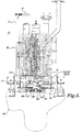
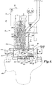
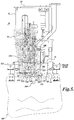
- Filler head assembly 100 is shown in FIGURES 1-4 , 7 and 8 , in upward retracted position, and in FIGURES 5 and 6 in downward extended position.
- the filler head assembly 100 includes a leading head structure 102 defining an annular shaped cavity 104, and a downwardly extending nipple or tip 106.
- a valve 108 is positioned at the intersection of the cavity 104 and nipple 106 to open and close the head structure 102.
- a product inflow tube 110 intersects the head structure 102 to deliver liquid product into the cavity 104.
- the tube 110 is connected to a source of food product, not shown.
- the filler head assembly 100 is extended and retracted by an appropriate mechanism,
- a central opening is formed in the floor plate structure 64 of the filler chamber 60.
- this opening is plugged or closed off by the plug assembly 300, which is shown in place in FIGURES 1 , 2 , and 8 .
- the plug assembly 300 is removed from the floor plate structure and retracted away to the left side of the filler chamber.
- the plug assembly 300 includes a plug structure 302 composed of a plug body 304 that snuggly engages within the central opening formed in the floor plate structure 64.
- a seal 306 is seated within a groove extending around the floor plate structure opening to seal against the plug body 304.
- the plug structure 302 includes a top 310 having a diameter somewhat larger than the diameter of the plug body 304. In FIGURE 2 , a portion of the plug structure 302 is broken away so that the construction of plug body 304 is visible.
- a bracket 312 connects the plug top to an actuator assembly 314 that is moveable vertically and also rotatable about a vertical axis 316.
- the actuator assembly 314 is extendable downwardly to engage the plug assembly into the floor plate structure hole, and also to retract the plug assembly upwardly to remove the plug assembly from the floor plate structure hole and then rotate the plug assembly away from the central portion of the fill chamber to a position on the left side of the fill chamber 60, as shown in FIGURES 3-7 .
- the actuator assembly 314 is mounted on the frame structure 50 by appropriate brackets or other mounting structure.
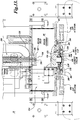
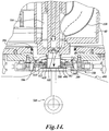
- a fitment chamber 200 is positioned below the filler chamber 60. Enlarged views of the fitment chamber 200 are shown in FIGURES 13 and 14 .
- the fitment chamber 200 is formed by the floor plate structure 64, as well as by a housing 202 that is attached to the underside of the floor plate structure.
- the housing 202 has a central cavity 204 of substantially the same diameter as the floor plate structure opening.
- a steam inlet line 206 and a steam outlet line 208 engage with passageways, not shown, formed in the housing 202 between the exterior perimeter of the housing and the central cavity 204.
- Control valves 210, 212, 214, and 216 control the flow of steam into and out of the cavity 204, as desired, for example, when sterilizing the fitment closure 402, as described below.
- a holder assembly 350 is employed to hold the fitment closure 402 in place during filling of the bag 400.
- the fitment holder assembly 350 is mounted to the underside of the fitment chamber housing 202.
- the fitment holder assembly 350 includes a pair of slide plates 352 that slide within spaced-apart parallel slideways 354 mounted to the underside of housing 202.
- the slideways 354 define longitudinal grooves 356 that closely receive the side edge portions of the slide plates 352.
- the center portions of the slide plates 352 cooperatively define a circular opening for receiving jaws 360 which is positioned within a shallow counter-bore formed in the slide plates.
- the jaws 360 are constructed of two halves, with a semi-circular central opening. As shown in FIGURES 13 and 14 , the jaws 360 engage within a close-fitting groove 406 formed in the collar 408 of fitment 402.
- the groove 406 is formed by spaced-apart flanges 410 and 412 extending radially outwardly from the collar 408.
- the jaws 360 can be composed of any suitable material, for example, stainless steel or other metallic material, or other types of material, such as ceramic material.
- An elastomeric seal 362 is located above jaw 360 to seal against the flange 412 that forms the upper side of the fitment groove in which the jaw 360 engages.
- the elastomeric seal 362 is backed by a backing ring 364 that overlies the jaws 360.
- the seal 362 is semi-circular in shape so as to cooperatively form a complete circular shape when the slide plates 352 are engaged around fitment 402.
- linear actuators 370 which may be powered by a gas, such as air, or a fluid, such as hydraulic fluid, in a well known manner.
- the actuators 370 are mounted to mounting brackets 372, which in turn are secured to the underside of floor plate structure 64, see FIGURES 13 and 19 .
- the forward ends of linear actuators 370 extend through close-fitting openings formed in the mounting brackets 372, and are held in place by lock nuts 374 that engage with threaded collars extending forwardly from the forward end of the actuator bodies.
- the forward ends of actuator rods 376 are connected to anchor brackets 378, which in turn are secured to the corresponding portions of slide plates 352.
- the forward ends of the actuator rods 376 may be threaded to engage threaded bores formed in the brackets 378, with the rods 376 held in place by lock nuts 380. It will be appreciated that by the foregoing construction, a very reliable and robust structure is provided for the fitment holder assembly 350.
- the fitment closure 402 is in place in the fitment chamber and being held by the fitment holder assembly 350, prior to filling the bag 400 the fitment cap 404 is removed. However, as discussed more fully below, before the fitment cap is removed, the fitment 402 is sterilized by steam introduced into the fitment chamber 200 through a steam inlet line 206. During such sterilization of the fitment, the filler chamber plug assembly 300 is engaged in the fitment chamber opening formed in the floor plate structure 64, as shown in FIGURES 2 and 13 .
- FIGURE 3 illustrates the fitment cap removal/replacement apparatus 450 as engaged with the fitment cap 404.
- the fitment cap 404 is being removed from the fitment collar 408.
- FIGURE 7 illustrates the fitment cap 404 being replaced over the fitment collar 408 after the bag 400 has been filled.
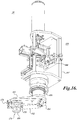
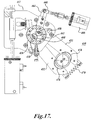
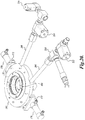
- FIGURES 15-18 show additional views of the fitment cap removal and replacement apparatus 450.
- the fitment cap removal/replacement apparatus 450 includes a pair of clamp arms 452 that project from a pivot head 454, located at the lower end of a pivot cylinder 456.
- the ends of the pivot arms 452 at the pivot head 454 are secured to the lower ends of pivot rods 458 that extend downwardly through the pivot cylinder 456, that extends downwardly from a frame structure 457, see FIGURE 17 .
- Segment gears 460 and 462 are attached to the upper ends of the pivot rods 458.
- the segment gears 460 and 462 mesh with each other, as shown in FIGURE 17 .
- the segment gear 462 is attached or integrated into an end portion of a pivot arm 464 that projects outwardly from pivot cylinder 456.
- the distal end of the pivot arm 464 is connected to a linear actuator 466 via clevis 468 connected between the distal end of pivot arm 464 and a connecting rod extending from actuator 466. It will be appreciated that actuator 466 is operated to control the rotation of clamp arms 452 from an open or spread position, as shown in FIGURES 16 and 17 , to a closed position as shown in FIGURE 18 .
- An extension spring 470 is connected between the distal end portions of clamp arms 452 to bias the clamp arms in closed position.
- an attachment head 476 is mounted near the distal end portions of the clamp arms 452.
- the attachment head 476 includes two halves, that cooperatively define a generally cylindrical or circular shape.
- the attachment head 476 includes a generally cylindrical body portion 478 and an inwardly extending flange portion 480 at the lower edge portion of the body portion.
- the flange portion 480 is sized to underlie the upper rim of the fitment cap, thereby to lift the cap upwardly when removing the cap from the fitment collar.
- the pivot cylinder 456 of the apparatus 450 is moveable vertically relative to frame 457 and also rotatably about the longitudinal axis of the pivot cylinder.
- FIGURE 7 shows the fitment cap 404 replaced by the apparatus 450.
- a fitment plug assembly 500 is provided to close off the bottom of the fitment collar from the interior of the bag 400 at various portions of the filling cycle for the bag 400; for instance, when the fitment is being sterilized, when the fitment cap is being removed and before the fill process starts, and during the process of replacing the fitment cap after the bag has been filled.
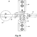
- the plug assembly 500 includes plug 502 mounted on the distal end portion of a pivot arm 504.
- the opposite end of the pivot arm is rotatably axled on cross pin 506 which spans between, and is held in place by, two spaced-apart mounting brackets 508 that are secured to the underside of the fitment chamber housing 202.
- a bushing 510 is interposed between the cross pin 506 and a close-fitting cross-bore extending through the pivot arm 504 so that the pivot arm rotates freely relative to the cross pin..
- a portion of the pivot arm shown in FIGURE 10 is broken away to illustrate this construction.
- the pivot arm 504 includes a transverse lug 512, shown extending downwardly from the pivot arm 504 in FIGURE 11 .
- the distal end of an actuator rod 514 is connected to the lug 512 via a clevis 516 engaging through a cross hole formed in the lug.
- the actuator rod 514 is part of linear actuator 518.
- the opposite end of the linear actuator includes a pair of spaced-apart mounting ears 520 that are pinned to a bracket 522 depending downwardly from the floor plate structure 64 of the apparatus frame 50.
- the plug 502 is constructed of a resilient upper plug layer 530 and a lower backing layer 532.
- the upper plug layer is constructed of rubber, synthetic rubber, a resilient plastic material or other durable but resilient material that is capable of sealing against the bottom of collar 408 to form a seal against the collar.
- the upper plug layer 530 is chamfered or radiused to provide a relatively tight seal against the lower end of collar 408.
- the backing layer 532 provides a support for the upper plug layer 530 on the pivot arm 504, which is substantially narrower than the diameter of the upper plug layer 530.
- the linear actuator 518 when extended pivots the plug 502 into position against the bottom of the fitment collar 408. In this manner, the plug remains exterior of the bag 400 and thus is not a source of possible contamination with the bag. Moreover, the portion of the bag interposed between the bottom of the collar 408 and the plug 502 can serve as a gasket or seal to positively close off the bottom of the collar 408.
- the plug assembly 500 When in such position, the plug assembly 500 is exterior of the bag 400, and thus, part of the bag is disposed between the upper surface of the plug 502 and the bottom of the fitment collar 408.
- the plug 502 When the actuator 518 is in contracted condition, the plug 502 is rotated away approximately 90 degrees from the fitment chamber 200 and the associated fitment 402, for example, as shown in FIGURES 1 , 5 , and 6 .
- the plug assembly 500 closes off the bottom of the fitment collar from the interior of the bag itself. This is important when removing the fitment cap 404 from the fitment collar 408 in preparation to begin filling the bag.
- the pressure within the filler chamber 60 is maintained so as to retain the aseptic condition within the pressurized filler chamber. Proof of a positive pressure level in the filler chamber is a regulatory requirement in certain countries for aseptic filler systems. But for the position of the fitment plug 502 at the bottom of the fitment collar, when the fitment cap is removed, the steam or other moisture from the filler chamber would otherwise enter the filler bag and thereby drastically reduce the pressure within the filler chamber.
- the fitment plug is again positioned against the lower end of the fitment collar to isolate or close off the fitment bag from the filler chamber. Since a filled bag, such as bag 400, is not filled to such an extent that there does not remain an empty or unfilled volume at the top of the bag, the engaged fitment plug 502 does not place a significant strain on the bag, even when filled. The positioning of the fitment plug against the lower end of the fitment collar not only helps maintain the positive (over) pressure within the filler chamber, but also prevents undesirable fluids from entering the filler bag.
- the fitment plug assembly can be retracted so that thereafter, the fitment can be released by the fitment holder assembly 350 and the bag removed from the filler apparatus, as shown in FIGURE 8 .
- Chart A sets forth the positions of filler head assembly 100, filler chamber plug assembly 300, fitment collar holder assembly 350, fitment cap remover/retractor apparatus 450, and fitment plug assembly 500 during the fill cycle.
- Fill Chamber in Ready Condition 1 In Place - Closing off Fill Chamber Retracted Retracted Retracted Retracted Retracted 2.
- the filler apparatus 30 is shown in standby or ready condition.
- the bottom opening of the fill chamber is closed by the fill chamber plug assembly 300 inserted into the center opening formed in the floor plate structure 64.
- the filler head assembly 100 is retracted in upward position.
- the fitment plug assembly 500 is shown in retracted position, and thus swung away from the fitment chamber 200.
- the fitment 402 is held in place within the fitment chamber 200 by the fitment holder assembly 350.
- the fitment plug assembly 500 is in engaged position so that the fitment plug 502 bears against the bottom of the fitment collar 408.
- the top of the fitment chamber is still closed off by the fill chamber plug assembly 300. During this portion of the fill cycle, steam is introduced into the fitment chamber so as to sterilize the fitment 402.
- FIGURE 3 shows the removal/replacement assembly 450 engaged with the fitment cap 404.
- the fitment collar 408 is held tightly in place by the fitment holder assembly 350, and the plug 502 of the fitment plug assembly 500 is engaged against the underside of the fitment collar 408. The operation of the fitment cap removal/replacement assembly has been described above.
- FIGURE 4 shows the fitment cap 404 removed and the fitment cap removal/replacement apparatus pivoted to temporarily position the fitment cap away from the fitment chamber 200.
- the plug 502 of the fitment plug assembly 500 is retained tightly against the underside of the fitment collar, thereby preventing loss of pressure within the fill chamber and also preventing undesirable fluids from entering the bag 400.
- FIGURES 5 , 6 , and 14 illustrate the filling of the bag 400 with desired liquid food product.
- the filler head assembly 100 is extended downwardly so that the nipple 106 is disposed within the interior of the fitment collar 408.
- Food products from product inflow tube 110 can flow into and through the head structure 102 and then downwardly through the nipple 106, through the fitment collar 408, and into the interior of the bag 400.
- a fitment plug assembly 500 is retracted so as to not obstruct the flow of the food product through the fitment collar.
- the filler head assembly 100 is retracted upwardly to disengage the nipple 106 from the fitment collar, see FIGURE 7 .
- the fitment cap 404 is replaced by the fitment cap removal and replacement apparatus 450.
- the operation of the apparatus 450 is described above.
- the fitment plug assembly is in engaged position so that the plug 502 is against the underside of the fitment collar 408, thereby to prevent loss of pressure within the fitment chamber as well as prevent undesirable fluids from entering the bag 400 after the filler head assembly 100 has been retracted and before the fitment cap 404 has been placed back over the fitment collar.
- the fitment 402 can be released from the fitment holder assembly 350.
- the fitment plug assembly 500 is retracted so as not to hinder the removal of the fitment from the fitment holder assembly 350.
- the filled bag 400 is removed from the filler apparatus 30, as illustrated in FIGURE 8 . It will be appreciated that steam can be introduced into the fitment chamber 200 after removal of the bag 400 to clean the fitment chamber if necessary.
- the operation of the described fill cycle is controlled and sequenced by a control system that is capable of actuating the various systems and components of the fill system described above.
- the control system includes software that can be operated and manipulated to adjust the fill system 30 and fill cycle to accommodate the particular food or other product being delivered to the filler bag 400, as well as the size and other aspects of the filler bag.
- a user interface may be provided that can be used to operate, manipulate and/or adjust the fill system 30 and fill cycle of the present disclosure.
- the fill system and process of the present disclosure are specifically advantageous for use with low acid food packaging, the system and process can be used with aseptically filling flexible containers with all manner of flowable food products.
- the fill system of the present disclosure can also be used with the aseptic filling of flexible containers with flowable products in addition to food products, for example, cosmetic products or medications.
Landscapes
- Engineering & Computer Science (AREA)
- Mechanical Engineering (AREA)
- Chemical & Material Sciences (AREA)
- Dispersion Chemistry (AREA)
- Vacuum Packaging (AREA)
- Basic Packing Technique (AREA)
- Bag Frames (AREA)
Claims (15)
- Aseptische Füllstoffvorrichtung (30), die in einem Füllzyklus betreibbar ist, um flexible Beutel (400) mit Lebensmittelprodukten zu füllen, wobei der flexible Beutel mit einem Anschlussstück (402) ausgestattet ist, das aus einem Kragen (408), der nominell mit dem Beutel in Lebensmittel-Fließverbindung steht, und einer abnehmbaren Kappe (404) zusammengesetzt ist, die mit dem Kragen in Eingriff bringbar ist, wobei die Füllstoffvorrichtung Folgendes umfasst:eine geschlossene Füllstoffkammer (60);einen Füllstoffkopf (100), der in der Füllstoffkammer angeordnet ist, um Lebensmittelprodukte durch das Anschlussstück in den Beutel zu leiten; undeine Halteranordnung (350) zum Halten des Anschlussstücks während des Befüllens des Beutels über den Füllstoffkopf;wobei die aseptische Füllstoffvorrichtung durch Folgendes gekennzeichnet ist:eine Anschlussstückkammer (200), die mit der Füllstoffkammer (60) und der Halteranordnung (380) in Verbindung steht, die das Anschlussstück (402) während des Befüllens des flexiblen Beutels stationär in der Anschlussstückkammer (200) hält; undeine Anschlussstückstopfen-Anordnung (500), die zwischen Folgendem beweglich ist: einer betätigten Position, um an dem Anschlussstückkragen anzuliegen, um eine Verbindung zwischen der Füllstoffkammer und dem Inneren des Beutels während gewünschter Abschnitte des Füllzyklus zu blockieren; und einer zurückgezogenen Position, in der ein Anschlussstückstopfen (502) weg vom Anschlussstückkragen beabstandet ist, um die Lebensmittel-Fließverbindung zwischen der Füllkammer und dem Inneren des Beutels nicht zu behindern.
- Füllstoffvorrichtung nach Anspruch 1, wobei die Anschlussstückstopfen-Anordnung (500) außerhalb des flexiblen Beutels positioniert ist.
- Füllstoffvorrichtung nach Anspruch 1 oder 2, wobei, wenn sich die Anschlussstückstopfen-Anordnung (500) in einer betätigten Position befindet, ein Abschnitt des Beutels (400) zwischen dem Anschlussstückkragen (408) und dem Anschlussstückstopfen (502) angeordnet ist.
- Füllstoffvorrichtung nach einem der Ansprüche 1 bis 3, wobei die Anschlussstückstopfen-Anordnung (500), wenn sie sich in der betätigten Position befindet, den Verbindungsstückkragen (408) am Schnittpunkt des Verbindungsstückkragens und des Beutels (400) verschließt, sodass eine Verbindung zwischen der Füllstoffkammer (60) und dem Inneren des Beutels verhindert wird.
- Füllstoffvorrichtung nach einem der Ansprüche 1 bis 4, wobei die Anschlussstückstopfen-Anordnung (500) eine Aktuatoranordnung (518) zum Bewegen des Anschlussstückstopfens (502) zwischen der betätigten Position und der zurückgezogenen Position der Anschlussstückstopfen-Anordnung umfasst, wobei die Aktuatoranordnung einen Schwenkarm (504) zum Stützen des Anschlussstückstopfens (502) und einen Aktuator (518) zum Bewegen des Schwenkarms zwischen der betätigten Position der Anschlussstückstopfen-Anordnung und der zurückgezogenen Position der Anschlussstückstopfen-Anordnung umfasst.
- Füllstoffvorrichtung nach einem der Ansprüche 1 bis 5, die ferner eine Vorrichtung (450) zum Entfernen und Auswechseln von Anschlussstückkappen umfasst, wobei die Vorrichtung zum Entfernen und Auswechseln von Kappen mit der Anschlussstückkappe (404) in Eingriff bringbar ist, um die Anschlussstückkappe von dem Anschlussstückkragen 408) zu entfernen, um dadurch während des Befüllens des Beutels (400) durch den Füllstoffkopf (100) Zugang zum Anschlussstückkragen und das Auswechseln Anschlussstückkappe in Eingriff mit dem Anschlussstückkragen bereitzustellen.
- Füllstoffvorrichtung nach einem der Ansprüche 1 bis 6, ferner umfassend:eine Quelle von Dampf;ein Dampfabgabesystem (206, 210, 212) zum Leiten des Dampfes von der Dampfquelle zu der Anschlussstückkammer (200) und,ein Dampfentfernungssystem (208, 214, 216) zum Leiten von Dampf aus der Anschlussstückkammer.
- Füllstoffvorrichtung nach Anspruch 7, ferner umfassend einen Dampfeinlass (206), der mit der Anschlussstückkammer (200) zum Verbinden der Anschlussstückkammer mit einer Dampfquelle in Verbindung steht, und einen Dampfauslass (208), der mit der Anschlussstückkammer zum Ausstoßen von Dampf aus der Anschlussstückkammer in Verbindung steht.
- Füllstoffvorrichtung nach einem der Ansprüche 1 bis 8, wobei die Anschlussstückkammer (200) unterhalb der Füllstoffkammer (60) angeordnet ist.
- Füllstoffvorrichtung nach einem der Ansprüche 1 bis 9, wobei die Anschlussstückkammer (200) vor der Umgebung abgedichtet ist, wenn das Anschlussstück (402) in der Anschlussstückkammer gehalten wird.
- Verfahren zum aseptischen Befüllen eines flexiblen Beutels (400) mit fließfähigen Lebensmitteln an einer Füllstoffkammer (60), in der ein Füllstoffkopf (100) untergebracht ist, der mit einer Quelle eines fließfähigen Lebensmittelprodukts verbindbar ist, wobei der flexible Beutel ein Anschlussstück (402) aufweist, das aus einem Anschlussstückkragen, der mit dem Inneren des Beutels in Lebensmittel-Fließverbindung steht, und einer Kappe (404) zum Verschließen an dem Anschlussstückkragen gegenüber dem flexiblen Beutel zusammengesetzt ist, wobei das Verfahren Folgendes umfasst:Schließen der Verbindung zwischen der Füllstoffkammer (60) und dem Inneren des flexiblen Beutels (400);Entfernen der Anschlussstückkappe (404) während des Schließens der Verbindung zwischen der Füllstoffkammer (60) und dem Inneren des Beutels (400);Positionieren des Füllstoffkopfes (100) in Lebensmittel-Fließverbindung mit dem Anschlussstückkragen (408);Wiederherstellen der Verbindung zwischen der Füllstoffkammer (60) und dem Inneren des flexiblen Beutels (400);Leiten des fließfähigen Lebensmittelprodukts durch den Füllstoffkopf (100) zu dem flexiblen Beutel (400);Beenden des Flusses des fließfähigen Lebensmittels durch den Füllstoffkopf (100) und Schließen der Lebensmittel-Fließverbindung zwischen dem Anschlussstückkragen (408) und dem Beutel (400);Entfernen des Füllstoffkopfes (100) aus dem Anschlussstückkragen (408);Ersetzen der Anschlussstückkappe (404) an dem Anschlussstückkragen (408); undÖffnen der Lebensmittel-Fließverbindung zwischen dem Anschlussstückkragen (408) und dem Beutel (400);gekennzeichnet durch:Vor dem Schließen der Verbindung zwischen der Füllstoffkammer (60) und dem Inneren des flexiblen Beutels (400), Anordnen des Anschlussstücks (432) in einer Anschlussstückkammer (200), wobei die Anschlussstückkammer mit der Füllstoffkammer (60) in Verbindung steht, und Halten des Anschlussstücks vertikal stationär in der Anschlussstückkammer; undEntfernen des Anschlussstücks (402) aus der Anschlussstückkammer (200) nach Öffnen der Lebensmittel-Fließverbindung zwischen dem Anschlussstückkragen (408) und dem Beutel (400).
- Verfahren nach Anspruch 11, wobei das Schließen der Verbindung zwischen dem Anschlussstückkragen (408) und dem Beutel (400) das Anordnen einer Barriere (502) an dem Kragen (408) am Schnittpunkt des Kragens (408) und des Beutels (400) umfasst.
- Verfahren nach Anspruch 12, wobei die Barriere (502) an einen Anschlussstückkragen (408) angelegt wird, wobei sich die Barriere außerhalb des Beutels (400) befindet.
- Verfahren nach Anspruch 12, wobei das Anlegen einer Barriere (502) an den Anschlussstückkragen (408) am Schnittpunkt des Anschlussstückkragens (408) und des Beutels (400) Folgendes umfasst:Anlegen eines Anschlussstückstopfens (502) an den Anschlussstückkragen am Schnittpunkt des Anschlussstückkragens und des Beutels; undwobei der Anschlussstückstopfen zwischen einer Eingriffsposition, wobei der Anschlussstückstopfen an dem Anschlussstückkragen angeordnet ist, und einer zurückgezogenen Position beweglich ist, wobei der Anschlussstückstopfen weg von dem Anschlussstückkragen angeordnet ist.
- Verfahren nach Anspruch 11, wobei sich die Anschlussstückkammer (200) unterhalb der Anschlussstückkammer (60) befindet.
Priority Applications (1)
| Application Number | Priority Date | Filing Date | Title |
|---|---|---|---|
| PL14733011T PL2999633T3 (pl) | 2013-05-21 | 2014-05-20 | Aseptyczny wypełniacz do produktów płynnych |
Applications Claiming Priority (2)
| Application Number | Priority Date | Filing Date | Title |
|---|---|---|---|
| US13/899,472 US10059476B2 (en) | 2013-05-21 | 2013-05-21 | Aseptic filler for flowable products |
| PCT/US2014/038835 WO2014189965A1 (en) | 2013-05-21 | 2014-05-20 | Aseptic filler for flowable products |
Publications (2)
| Publication Number | Publication Date |
|---|---|
| EP2999633A1 EP2999633A1 (de) | 2016-03-30 |
| EP2999633B1 true EP2999633B1 (de) | 2017-12-13 |
Family
ID=51014630
Family Applications (1)
| Application Number | Title | Priority Date | Filing Date |
|---|---|---|---|
| EP14733011.2A Active EP2999633B1 (de) | 2013-05-21 | 2014-05-20 | Aseptischer füllstoff für fliessfähige produkte |
Country Status (8)
| Country | Link |
|---|---|
| US (1) | US10059476B2 (de) |
| EP (1) | EP2999633B1 (de) |
| CA (1) | CA2911320C (de) |
| ES (1) | ES2661821T3 (de) |
| MX (1) | MX386248B (de) |
| PL (1) | PL2999633T3 (de) |
| PT (1) | PT2999633T (de) |
| WO (1) | WO2014189965A1 (de) |
Families Citing this family (16)
| Publication number | Priority date | Publication date | Assignee | Title |
|---|---|---|---|---|
| WO2012172576A1 (en) * | 2011-06-14 | 2012-12-20 | Cft S.P.A. | System for aseptic filling of big containers with an outlet. |
| EP3127859B1 (de) * | 2015-08-07 | 2020-07-08 | INDAG Pouch Partners GmbH | Verfahren zum aseptischen füllen eines behältnisses, eine sterilfüllvorrichtung dazu, eine aseptikmaschine |
| US10035614B2 (en) * | 2015-09-21 | 2018-07-31 | Scholle Ipn Corporation | Method for aseptic filling of pouches |
| US10189591B2 (en) * | 2015-09-21 | 2019-01-29 | Scholle Ipn Corporation | Rotary filling device for aseptic filling of pouches |
| IT201700047199A1 (it) * | 2017-05-02 | 2018-11-02 | Goglio Spa | Tappo a pressione e contenitore ermetico dotato di tale tappo a pressione |
| DE102018108760A1 (de) * | 2018-04-12 | 2019-10-17 | Khs Corpoplast Gmbh | Verfahren und Vorrichtung zum Befüllen von Behältern mit karbonisiertem Füllgut und dem anschließenden Verschließen der gefüllten Behälter |
| ES2758362B2 (es) * | 2018-11-02 | 2021-03-29 | Farm Rovi Lab Sa | Procedimiento para el llenado de sólidos en contenedores farmacéuticos y sellado de los mismos en condiciones estériles |
| US10934039B2 (en) * | 2018-12-31 | 2021-03-02 | Dow Global Technologies Llc | Support system for filling a flexible container |
| CA3192522A1 (en) * | 2020-09-16 | 2022-03-24 | Avure Technologies Incorporated | System for bulk high pressure processing and related method |
| US11352244B1 (en) * | 2020-12-03 | 2022-06-07 | John Bean Technologies Corporation | Sanitary fill head |
| US11518560B1 (en) * | 2021-02-12 | 2022-12-06 | Timothy E. Orr | Method and apparatus for eliminating oxygen in the filling of a flexible bag with a beverage |
| IT202100005594A1 (it) * | 2021-03-10 | 2022-09-10 | Ali Group S R L | Apparato di riempimento di contenitori di alimentazione e procedimento corrispondente. |
| FR3126123B1 (fr) * | 2021-08-12 | 2023-07-28 | Smurfit Kappa Bag In Box | Procédé et machine de remplissage d’outres. |
| SK289342B6 (sk) * | 2022-03-02 | 2025-07-30 | Ján Šofranko | Zariadenie a spôsob aseptického plnenia obalov |
| US11999519B2 (en) | 2022-08-04 | 2024-06-04 | Scholle Ipn Corporation | Filler assembly and method of filling a pouch |
| EP4660090A1 (de) * | 2024-06-03 | 2025-12-10 | Alfa Laval Corporate AB | Verfahren und füllvorrichtung zum befüllen von flexiblen behältern mit fliessfähigen produkten |
Family Cites Families (23)
| Publication number | Priority date | Publication date | Assignee | Title |
|---|---|---|---|---|
| US3310078A (en) * | 1964-05-05 | 1967-03-21 | Gen Tire & Rubber Co | Semi-automatic filling device |
| US4120134A (en) * | 1977-07-05 | 1978-10-17 | Scholle Corporation | Apparatus for and method of filling flexible containers |
| JPS56113528A (en) | 1980-02-05 | 1981-09-07 | Dainippon Printing Co Ltd | Germless filling method |
| BR8200115A (pt) * | 1981-01-13 | 1982-11-03 | Wrightcel Ltd | Aparelho para enchimento de recipientes felxiveis |
| IN159651B (de) | 1982-03-10 | 1987-05-30 | El Srl | |
| US4445550B1 (en) | 1982-08-20 | 1999-03-09 | Scholle Corp | Flexible walled container having membrane fitment for use with aseptic filling apparatus |
| US4494363A (en) * | 1982-08-20 | 1985-01-22 | Franrica Mfg. Inc. | Method and apparatus for aseptically filling containers |
| US4498508A (en) | 1983-02-04 | 1985-02-12 | Scholle Corporation | Container filler |
| EP0212201A1 (de) * | 1985-07-24 | 1987-03-04 | Ingko GmbH Industrieanlagenbau | Vorrichtung und Verfahren zur luftfreien Befüllung von Behältnissen, insbesondere von flexiblen Beuteln |
| CH674637A5 (de) * | 1987-11-25 | 1990-06-29 | Nestle Sa | |
| GB8824925D0 (en) * | 1988-10-25 | 1988-11-30 | Bowater Packaging Ltd | Aseptic filling apparatus |
| IT1225214B (it) * | 1988-11-25 | 1990-11-02 | El Srl | Dispositivo per la sterilizzazione dell'imboccatura di contenitori, inparticolare di contenitori a forma di sacco per prodotti alimentari |
| CH679768A5 (de) * | 1989-05-02 | 1992-04-15 | Nestle Sa | |
| US5129212A (en) * | 1990-11-08 | 1992-07-14 | Liqui-Box/B-Bar-B Corporation | Method and apparatus for automatically filling and sterilizing containers |
| US5447699A (en) * | 1993-11-17 | 1995-09-05 | The West Company | Combination container for holding sterilized elements and a sterilizable transfer port |
| US5479955A (en) * | 1994-05-31 | 1996-01-02 | Spartanburg Steel Products, Inc. | Method and apparatus for aseptically filling containers |
| DE19544708A1 (de) * | 1995-11-30 | 1997-06-12 | Helmut Geis | Behälter, Behälterverschlußkappe, Verfahren und Maschine zum kaltaseptischen Befüllen mit Getränken |
| US6070622A (en) * | 1998-05-07 | 2000-06-06 | Packaging Systems, L.L.C. | High speed aseptic filling machine |
| FR2796040B1 (fr) * | 1999-07-07 | 2001-10-19 | Calhene | Procede de transfert de produits aseptiques entre deux enceintes et conteneur de transport pour la mise en oeuvre de ce procede |
| GB9916215D0 (en) | 1999-07-09 | 1999-09-15 | Smith David S Packaging | Apparatus and method for filling |
| EP1868897B1 (de) * | 2005-03-30 | 2009-05-06 | F B R - Elpo - Societa'Per Azioni | Maschine zum füllen von abgedichteten weichen behältern in einer aseptischen umgebung und verfahren zu ihrem füllen |
| US7708959B2 (en) * | 2006-07-20 | 2010-05-04 | Scholle Corporation | Sterilization system and method suitable for use in association with filler devices |
| GB2452055A (en) | 2007-08-22 | 2009-02-25 | Flexifill Ltd | Aseptic container filling |
-
2013
- 2013-05-21 US US13/899,472 patent/US10059476B2/en active Active
-
2014
- 2014-05-20 MX MX2015016063A patent/MX386248B/es unknown
- 2014-05-20 WO PCT/US2014/038835 patent/WO2014189965A1/en not_active Ceased
- 2014-05-20 CA CA2911320A patent/CA2911320C/en active Active
- 2014-05-20 ES ES14733011.2T patent/ES2661821T3/es active Active
- 2014-05-20 PL PL14733011T patent/PL2999633T3/pl unknown
- 2014-05-20 EP EP14733011.2A patent/EP2999633B1/de active Active
- 2014-05-20 PT PT147330112T patent/PT2999633T/pt unknown
Also Published As
| Publication number | Publication date |
|---|---|
| US20140345233A1 (en) | 2014-11-27 |
| CA2911320C (en) | 2021-06-01 |
| CA2911320A1 (en) | 2014-11-27 |
| MX386248B (es) | 2025-03-18 |
| WO2014189965A8 (en) | 2016-01-28 |
| PT2999633T (pt) | 2018-03-15 |
| PL2999633T3 (pl) | 2018-05-30 |
| EP2999633A1 (de) | 2016-03-30 |
| MX2015016063A (es) | 2016-08-03 |
| US10059476B2 (en) | 2018-08-28 |
| ES2661821T3 (es) | 2018-04-04 |
| WO2014189965A1 (en) | 2014-11-27 |
Similar Documents
| Publication | Publication Date | Title |
|---|---|---|
| US10059476B2 (en) | Aseptic filler for flowable products | |
| US4494363A (en) | Method and apparatus for aseptically filling containers | |
| EP0085564B1 (de) | Vorrichtung und Verfahren zum Füllen eines Behälters, insbesondere zum aseptischen Füllen | |
| NZ201610A (en) | Filling containers asceptically | |
| JP2744787B2 (ja) | 容器を無菌で充填する方法と装置 | |
| JPH0645367B2 (ja) | 充てん装置と方法 | |
| CN108290649B (zh) | 用于袋的无菌填充的旋转式填充装置 | |
| CA2543309A1 (en) | Container for food products and method for transporting food products | |
| US6330780B1 (en) | Apparatus and method for filling | |
| JP2003515509A (ja) | 容器を充填する装置 | |
| US5743313A (en) | Apparatus and method for emptying a container in an aseptic manner | |
| US6543495B2 (en) | Multiple access container and methods for the transfer of fluent materials | |
| US11352244B1 (en) | Sanitary fill head | |
| US20160244195A1 (en) | Installation for aseptic filling of a receptacle | |
| US20240076085A1 (en) | System for aseptically loading components into a pharmaceutical isolator | |
| US6848235B2 (en) | Adverse environment foil cap seal system | |
| CN100526164C (zh) | 用于在无菌环境下填装密封柔性容器的机器 | |
| US8201594B2 (en) | System and method for filling containers | |
| CN104271451A (zh) | 用于处理无菌食品产品的方法和设备 | |
| CZ2004999A3 (cs) | Způsob zpracování chybně naplněných obalů s nápoji a zařízení k provádění způsobu | |
| JPH0710686B2 (ja) | 袋への流体の無菌充填方法 | |
| FR2545787A1 (fr) | Dispositif de contre-pression equipant un systeme de conditionnement et de remplissage en milieu sterile | |
| US20060210685A1 (en) | Adiabatic and aseptic food packaging method and apparatus | |
| JP2001072128A (ja) | 充填・排出用治具及び無菌充填・排出方法 | |
| FR2485478A3 (fr) | Appareil d'emballage aseptique |
Legal Events
| Date | Code | Title | Description |
|---|---|---|---|
| PUAI | Public reference made under article 153(3) epc to a published international application that has entered the european phase |
Free format text: ORIGINAL CODE: 0009012 |
|
| 17P | Request for examination filed |
Effective date: 20151113 |
|
| AK | Designated contracting states |
Kind code of ref document: A1 Designated state(s): AL AT BE BG CH CY CZ DE DK EE ES FI FR GB GR HR HU IE IS IT LI LT LU LV MC MK MT NL NO PL PT RO RS SE SI SK SM TR |
|
| AX | Request for extension of the european patent |
Extension state: BA ME |
|
| DAX | Request for extension of the european patent (deleted) | ||
| STAA | Information on the status of an ep patent application or granted ep patent |
Free format text: STATUS: EXAMINATION IS IN PROGRESS |
|
| 17Q | First examination report despatched |
Effective date: 20161220 |
|
| GRAP | Despatch of communication of intention to grant a patent |
Free format text: ORIGINAL CODE: EPIDOSNIGR1 |
|
| STAA | Information on the status of an ep patent application or granted ep patent |
Free format text: STATUS: GRANT OF PATENT IS INTENDED |
|
| INTG | Intention to grant announced |
Effective date: 20170706 |
|
| GRAS | Grant fee paid |
Free format text: ORIGINAL CODE: EPIDOSNIGR3 |
|
| GRAA | (expected) grant |
Free format text: ORIGINAL CODE: 0009210 |
|
| STAA | Information on the status of an ep patent application or granted ep patent |
Free format text: STATUS: THE PATENT HAS BEEN GRANTED |
|
| REG | Reference to a national code |
Ref country code: GB Ref legal event code: FG4D |
|
| REG | Reference to a national code |
Ref country code: AT Ref legal event code: REF Ref document number: 954121 Country of ref document: AT Kind code of ref document: T Effective date: 20171215 Ref country code: CH Ref legal event code: EP |
|
| REG | Reference to a national code |
Ref country code: IE Ref legal event code: FG4D |
|
| REG | Reference to a national code |
Ref country code: DE Ref legal event code: R096 Ref document number: 602014018485 Country of ref document: DE |
|
| REG | Reference to a national code |
Ref country code: PT Ref legal event code: SC4A Ref document number: 2999633 Country of ref document: PT Date of ref document: 20180315 Kind code of ref document: T Free format text: AVAILABILITY OF NATIONAL TRANSLATION Effective date: 20180305 |
|
| REG | Reference to a national code |
Ref country code: ES Ref legal event code: FG2A Ref document number: 2661821 Country of ref document: ES Kind code of ref document: T3 Effective date: 20180404 |
|
| REG | Reference to a national code |
Ref country code: NL Ref legal event code: MP Effective date: 20171213 |
|
| PG25 | Lapsed in a contracting state [announced via postgrant information from national office to epo] |
Ref country code: FI Free format text: LAPSE BECAUSE OF FAILURE TO SUBMIT A TRANSLATION OF THE DESCRIPTION OR TO PAY THE FEE WITHIN THE PRESCRIBED TIME-LIMIT Effective date: 20171213 Ref country code: SE Free format text: LAPSE BECAUSE OF FAILURE TO SUBMIT A TRANSLATION OF THE DESCRIPTION OR TO PAY THE FEE WITHIN THE PRESCRIBED TIME-LIMIT Effective date: 20171213 Ref country code: NO Free format text: LAPSE BECAUSE OF FAILURE TO SUBMIT A TRANSLATION OF THE DESCRIPTION OR TO PAY THE FEE WITHIN THE PRESCRIBED TIME-LIMIT Effective date: 20180313 |
|
| REG | Reference to a national code |
Ref country code: FR Ref legal event code: PLFP Year of fee payment: 5 |
|
| REG | Reference to a national code |
Ref country code: AT Ref legal event code: MK05 Ref document number: 954121 Country of ref document: AT Kind code of ref document: T Effective date: 20171213 |
|
| PG25 | Lapsed in a contracting state [announced via postgrant information from national office to epo] |
Ref country code: RS Free format text: LAPSE BECAUSE OF FAILURE TO SUBMIT A TRANSLATION OF THE DESCRIPTION OR TO PAY THE FEE WITHIN THE PRESCRIBED TIME-LIMIT Effective date: 20171213 Ref country code: LV Free format text: LAPSE BECAUSE OF FAILURE TO SUBMIT A TRANSLATION OF THE DESCRIPTION OR TO PAY THE FEE WITHIN THE PRESCRIBED TIME-LIMIT Effective date: 20171213 Ref country code: HR Free format text: LAPSE BECAUSE OF FAILURE TO SUBMIT A TRANSLATION OF THE DESCRIPTION OR TO PAY THE FEE WITHIN THE PRESCRIBED TIME-LIMIT Effective date: 20171213 Ref country code: BG Free format text: LAPSE BECAUSE OF FAILURE TO SUBMIT A TRANSLATION OF THE DESCRIPTION OR TO PAY THE FEE WITHIN THE PRESCRIBED TIME-LIMIT Effective date: 20180313 |
|
| PG25 | Lapsed in a contracting state [announced via postgrant information from national office to epo] |
Ref country code: NL Free format text: LAPSE BECAUSE OF FAILURE TO SUBMIT A TRANSLATION OF THE DESCRIPTION OR TO PAY THE FEE WITHIN THE PRESCRIBED TIME-LIMIT Effective date: 20171213 |
|
| PG25 | Lapsed in a contracting state [announced via postgrant information from national office to epo] |
Ref country code: CY Free format text: LAPSE BECAUSE OF FAILURE TO SUBMIT A TRANSLATION OF THE DESCRIPTION OR TO PAY THE FEE WITHIN THE PRESCRIBED TIME-LIMIT Effective date: 20171213 Ref country code: EE Free format text: LAPSE BECAUSE OF FAILURE TO SUBMIT A TRANSLATION OF THE DESCRIPTION OR TO PAY THE FEE WITHIN THE PRESCRIBED TIME-LIMIT Effective date: 20171213 Ref country code: SK Free format text: LAPSE BECAUSE OF FAILURE TO SUBMIT A TRANSLATION OF THE DESCRIPTION OR TO PAY THE FEE WITHIN THE PRESCRIBED TIME-LIMIT Effective date: 20171213 Ref country code: CZ Free format text: LAPSE BECAUSE OF FAILURE TO SUBMIT A TRANSLATION OF THE DESCRIPTION OR TO PAY THE FEE WITHIN THE PRESCRIBED TIME-LIMIT Effective date: 20171213 |
|
| PG25 | Lapsed in a contracting state [announced via postgrant information from national office to epo] |
Ref country code: AT Free format text: LAPSE BECAUSE OF FAILURE TO SUBMIT A TRANSLATION OF THE DESCRIPTION OR TO PAY THE FEE WITHIN THE PRESCRIBED TIME-LIMIT Effective date: 20171213 Ref country code: SM Free format text: LAPSE BECAUSE OF FAILURE TO SUBMIT A TRANSLATION OF THE DESCRIPTION OR TO PAY THE FEE WITHIN THE PRESCRIBED TIME-LIMIT Effective date: 20171213 Ref country code: IS Free format text: LAPSE BECAUSE OF FAILURE TO SUBMIT A TRANSLATION OF THE DESCRIPTION OR TO PAY THE FEE WITHIN THE PRESCRIBED TIME-LIMIT Effective date: 20180413 Ref country code: RO Free format text: LAPSE BECAUSE OF FAILURE TO SUBMIT A TRANSLATION OF THE DESCRIPTION OR TO PAY THE FEE WITHIN THE PRESCRIBED TIME-LIMIT Effective date: 20171213 |
|
| REG | Reference to a national code |
Ref country code: GR Ref legal event code: EP Ref document number: 20180400679 Country of ref document: GR Effective date: 20180829 |
|
| REG | Reference to a national code |
Ref country code: DE Ref legal event code: R097 Ref document number: 602014018485 Country of ref document: DE |
|
| PLBE | No opposition filed within time limit |
Free format text: ORIGINAL CODE: 0009261 |
|
| STAA | Information on the status of an ep patent application or granted ep patent |
Free format text: STATUS: NO OPPOSITION FILED WITHIN TIME LIMIT |
|
| 26N | No opposition filed |
Effective date: 20180914 |
|
| PG25 | Lapsed in a contracting state [announced via postgrant information from national office to epo] |
Ref country code: DK Free format text: LAPSE BECAUSE OF FAILURE TO SUBMIT A TRANSLATION OF THE DESCRIPTION OR TO PAY THE FEE WITHIN THE PRESCRIBED TIME-LIMIT Effective date: 20171213 |
|
| REG | Reference to a national code |
Ref country code: CH Ref legal event code: PL |
|
| REG | Reference to a national code |
Ref country code: BE Ref legal event code: MM Effective date: 20180531 |
|
| PG25 | Lapsed in a contracting state [announced via postgrant information from national office to epo] |
Ref country code: MC Free format text: LAPSE BECAUSE OF FAILURE TO SUBMIT A TRANSLATION OF THE DESCRIPTION OR TO PAY THE FEE WITHIN THE PRESCRIBED TIME-LIMIT Effective date: 20171213 |
|
| REG | Reference to a national code |
Ref country code: IE Ref legal event code: MM4A |
|
| PG25 | Lapsed in a contracting state [announced via postgrant information from national office to epo] |
Ref country code: LI Free format text: LAPSE BECAUSE OF NON-PAYMENT OF DUE FEES Effective date: 20180531 Ref country code: SI Free format text: LAPSE BECAUSE OF FAILURE TO SUBMIT A TRANSLATION OF THE DESCRIPTION OR TO PAY THE FEE WITHIN THE PRESCRIBED TIME-LIMIT Effective date: 20171213 Ref country code: CH Free format text: LAPSE BECAUSE OF NON-PAYMENT OF DUE FEES Effective date: 20180531 |
|
| PG25 | Lapsed in a contracting state [announced via postgrant information from national office to epo] |
Ref country code: LU Free format text: LAPSE BECAUSE OF NON-PAYMENT OF DUE FEES Effective date: 20180520 |
|
| PG25 | Lapsed in a contracting state [announced via postgrant information from national office to epo] |
Ref country code: IE Free format text: LAPSE BECAUSE OF NON-PAYMENT OF DUE FEES Effective date: 20180520 |
|
| PG25 | Lapsed in a contracting state [announced via postgrant information from national office to epo] |
Ref country code: BE Free format text: LAPSE BECAUSE OF NON-PAYMENT OF DUE FEES Effective date: 20180531 |
|
| PG25 | Lapsed in a contracting state [announced via postgrant information from national office to epo] |
Ref country code: MT Free format text: LAPSE BECAUSE OF NON-PAYMENT OF DUE FEES Effective date: 20180520 |
|
| PG25 | Lapsed in a contracting state [announced via postgrant information from national office to epo] |
Ref country code: TR Free format text: LAPSE BECAUSE OF FAILURE TO SUBMIT A TRANSLATION OF THE DESCRIPTION OR TO PAY THE FEE WITHIN THE PRESCRIBED TIME-LIMIT Effective date: 20171213 |
|
| PG25 | Lapsed in a contracting state [announced via postgrant information from national office to epo] |
Ref country code: LT Free format text: LAPSE BECAUSE OF FAILURE TO SUBMIT A TRANSLATION OF THE DESCRIPTION OR TO PAY THE FEE WITHIN THE PRESCRIBED TIME-LIMIT Effective date: 20171213 Ref country code: HU Free format text: LAPSE BECAUSE OF FAILURE TO SUBMIT A TRANSLATION OF THE DESCRIPTION OR TO PAY THE FEE WITHIN THE PRESCRIBED TIME-LIMIT; INVALID AB INITIO Effective date: 20140520 Ref country code: MK Free format text: LAPSE BECAUSE OF NON-PAYMENT OF DUE FEES Effective date: 20171213 |
|
| PG25 | Lapsed in a contracting state [announced via postgrant information from national office to epo] |
Ref country code: AL Free format text: LAPSE BECAUSE OF FAILURE TO SUBMIT A TRANSLATION OF THE DESCRIPTION OR TO PAY THE FEE WITHIN THE PRESCRIBED TIME-LIMIT Effective date: 20171213 |
|
| REG | Reference to a national code |
Ref country code: FR Ref legal event code: PLFP Year of fee payment: 10 |
|
| P01 | Opt-out of the competence of the unified patent court (upc) registered |
Effective date: 20230426 |
|
| PGFP | Annual fee paid to national office [announced via postgrant information from national office to epo] |
Ref country code: DE Payment date: 20250325 Year of fee payment: 12 |
|
| PGFP | Annual fee paid to national office [announced via postgrant information from national office to epo] |
Ref country code: ES Payment date: 20250605 Year of fee payment: 12 |
|
| PGFP | Annual fee paid to national office [announced via postgrant information from national office to epo] |
Ref country code: IT Payment date: 20250422 Year of fee payment: 12 |
|
| PGFP | Annual fee paid to national office [announced via postgrant information from national office to epo] |
Ref country code: PT Payment date: 20250520 Year of fee payment: 12 |
|
| PGFP | Annual fee paid to national office [announced via postgrant information from national office to epo] |
Ref country code: GR Payment date: 20250416 Year of fee payment: 12 |
|
| PGFP | Annual fee paid to national office [announced via postgrant information from national office to epo] |
Ref country code: GB Payment date: 20260325 Year of fee payment: 13 |
|
| PGFP | Annual fee paid to national office [announced via postgrant information from national office to epo] |
Ref country code: FR Payment date: 20260323 Year of fee payment: 13 |
|
| PGFP | Annual fee paid to national office [announced via postgrant information from national office to epo] |
Ref country code: PL Payment date: 20260327 Year of fee payment: 13 |