EP2999656B1 - Antriebsstrang für hubwerke - Google Patents
Antriebsstrang für hubwerke Download PDFInfo
- Publication number
- EP2999656B1 EP2999656B1 EP14704560.3A EP14704560A EP2999656B1 EP 2999656 B1 EP2999656 B1 EP 2999656B1 EP 14704560 A EP14704560 A EP 14704560A EP 2999656 B1 EP2999656 B1 EP 2999656B1
- Authority
- EP
- European Patent Office
- Prior art keywords
- brake
- drive motor
- freewheel
- service brake
- load
- Prior art date
- Legal status (The legal status is an assumption and is not a legal conclusion. Google has not performed a legal analysis and makes no representation as to the accuracy of the status listed.)
- Not-in-force
Links
- 230000005540 biological transmission Effects 0.000 claims description 14
- 230000008878 coupling Effects 0.000 claims description 5
- 238000010168 coupling process Methods 0.000 claims description 5
- 238000005859 coupling reaction Methods 0.000 claims description 5
- 239000000446 fuel Substances 0.000 description 4
- 238000000926 separation method Methods 0.000 description 3
- 230000035939 shock Effects 0.000 description 3
- 238000010276 construction Methods 0.000 description 1
- 230000000694 effects Effects 0.000 description 1
- 239000007788 liquid Substances 0.000 description 1
- 230000002285 radioactive effect Effects 0.000 description 1
- 230000001960 triggered effect Effects 0.000 description 1
Images
Classifications
-
- B—PERFORMING OPERATIONS; TRANSPORTING
- B66—HOISTING; LIFTING; HAULING
- B66D—CAPSTANS; WINCHES; TACKLES, e.g. PULLEY BLOCKS; HOISTS
- B66D1/00—Rope, cable, or chain winding mechanisms; Capstans
- B66D1/02—Driving gear
- B66D1/14—Power transmissions between power sources and drums or barrels
-
- B—PERFORMING OPERATIONS; TRANSPORTING
- B66—HOISTING; LIFTING; HAULING
- B66D—CAPSTANS; WINCHES; TACKLES, e.g. PULLEY BLOCKS; HOISTS
- B66D1/00—Rope, cable, or chain winding mechanisms; Capstans
- B66D1/02—Driving gear
- B66D1/14—Power transmissions between power sources and drums or barrels
- B66D1/16—Power transmissions between power sources and drums or barrels the drums or barrels being freely rotatable, e.g. having a clutch activated independently of a brake
-
- B—PERFORMING OPERATIONS; TRANSPORTING
- B66—HOISTING; LIFTING; HAULING
- B66D—CAPSTANS; WINCHES; TACKLES, e.g. PULLEY BLOCKS; HOISTS
- B66D1/00—Rope, cable, or chain winding mechanisms; Capstans
- B66D1/02—Driving gear
- B66D1/12—Driving gear incorporating electric motors
-
- B—PERFORMING OPERATIONS; TRANSPORTING
- B66—HOISTING; LIFTING; HAULING
- B66D—CAPSTANS; WINCHES; TACKLES, e.g. PULLEY BLOCKS; HOISTS
- B66D1/00—Rope, cable, or chain winding mechanisms; Capstans
- B66D1/54—Safety gear
-
- B—PERFORMING OPERATIONS; TRANSPORTING
- B66—HOISTING; LIFTING; HAULING
- B66D—CAPSTANS; WINCHES; TACKLES, e.g. PULLEY BLOCKS; HOISTS
- B66D1/00—Rope, cable, or chain winding mechanisms; Capstans
- B66D1/54—Safety gear
- B66D1/58—Safety gear responsive to excess of load
-
- B—PERFORMING OPERATIONS; TRANSPORTING
- B66—HOISTING; LIFTING; HAULING
- B66D—CAPSTANS; WINCHES; TACKLES, e.g. PULLEY BLOCKS; HOISTS
- B66D5/00—Braking or detent devices characterised by application to lifting or hoisting gear, e.g. for controlling the lowering of loads
Definitions
- the invention relates to a drive train for hoists comprising a drive motor, a cable drum connected thereto, a reduction gear arranged between the drive motor and the cable drum, a service brake provided between the drive motor and the reduction gear, a safety brake and an automatic overrun fuel cutoff provided between the drive motor and the service brake ,
- hoists are provided for the transport of dangerous goods, such as liquid masses or radioactive masses, in the drive train in addition to the service brake usually also a safety brake is arranged.
- the safety brake which is used for emergency stop braking, usually sits on the shaft of the cable drum.
- the subject of the application is based on a completely different technical problem.
- the invention is intended to be based on the object to avoid the torque shock associated with the load reversal in the load case "LOWERING" and the resulting tension of the transmission.
- this object is achieved in that between the drive motor and the reduction gear, an automatic overrun fuel cutoff is provided, which responds in the load case "sinking" when the service brake and / or the safety brake.
- the rotating masses of the engine are disconnected from the drive train. This separation prevents damage to the powertrain and especially the reduction gearbox. additionally causes this separation a reduction of the stopping distance of the hoist or hanging on the hoist load.
- the overrunning clutch which is preferably designed as a freewheel, only rotates in the load case "LOWER" if the brakes are applied simultaneously when lowering. In such an operating situation, the output shaft of the transmission is then completely load-free.
- the freewheels used in the drive train according to the invention can be designed according to various design patterns, for example, they are provided with pinch rollers, sprags, pulleys, wrap springs or pawls.
- a particularly advantageous and suitable for the application of the invention construction of the freewheel is a clamping roller freewheel, which is not only very effective, but also works completely noiseless.
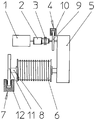
- the drive train according to the invention for a hoist consists of a drive motor 1, a freewheel 2, a clutch 3, a service brake 4, a reduction gear 5, a cable drum 6 and a Safety brake 7, which is especially prescribed for transporting dangerous goods.
- the safety brake 7 is seated on the same shaft 8 as the cable drum 6 and is connected downstream in the embodiment of the cable drum 6 shown in the drawing.
- the service brake 4 consists of a brake disc 9, which is surrounded at least on one side by a brake frame 10 with corresponding brake shoes.
- the safety brake 7 also comprises a brake disc 11, which is surrounded at least at one point by a brake frame 12, on which are provided correspondingly actuated brake shoes.
- Both the service brake 4 and the safety brake 7 are formed in the embodiment shown in the drawing in the manner of a disc brake.
- the arranged between the drive motor 1 and the clutch 3 freewheel 2 is expediently designed as a noiseless operating clamping roller freewheel.
- the arranged in the drawing between the freewheel 2 and the service brake 4 clutch 3 is designed as a rigid coupling.
- the clutch 3 may also be designed as an electrically switchable, releasable coupling in order to separate the drive motor 1 from the reduction gear 5.
- the clutch 3 could be dispensed with a freewheel 2.
Landscapes
- Engineering & Computer Science (AREA)
- Mechanical Engineering (AREA)
- Braking Arrangements (AREA)
- Transmission Devices (AREA)
- One-Way And Automatic Clutches, And Combinations Of Different Clutches (AREA)
Description
- Die Erfindung betrifft einen Antriebsstrang für Hubwerke mit einem Antriebsmotor, einer mit diesem verbundenen Seiltrommel, einem zwischen dem Antriebsmotor und der Seiltrommel angeordneten Untersetzungsgetriebe, einer zwischen dem Antriebsmotor und dem Untersetzungsgetriebe vorgesehenen Betriebsbremse, einer Sicherheitsbremse sowie einer zwischen dem Antriebsmotor und der Betriebsbremse vorgesehenen automatischen Schubabschaltung.
- Wenn Hubwerke für den Transport von gefährlichen Gütern vorgesehen sind, beispielsweise feuerflüssigen Massen oder auch radioaktiven Massen, ist in dem Antriebsstrang neben der Betriebsbremse in der Regel auch eine Sicherheitsbremse angeordnet. Die Sicherheitsbremse, die zur Not-Stopp-Bremsung dient, sitzt normalerweise auf der Welle der Seiltrommel.
- Bekannte Antriebsstränge der genannten Art (
DE 10 2004 062 515 A1 undEP 1 661 845 A1 ) sind unter dem Produktnamen "Snag Overload System" auf dem Markt. Dieses bekannte System wird insbesondere im Zusammenhang mit Containerkränen angewandt. Ein "Snag Overload" an einem Containerkran bedeutet, dass beim Heben des Containers beispielsweise aus einem Schiffsrumpf selbiger verklemmen kann (snag), wobei beim Eintritt eines solchen Falls eine Kupplung die Verbindung zwischen Motor und Getriebe ganz oder teilweise löst. Es ist also eine Kupplung vorgesehen, die zur vollständigen oder zumindest teilweisen Trennung der Verbindung vorgesehen ist, ohne dass die Verbindung selbständig wieder hergestellt wird und das System anschließend weiterarbeiten kann. Insofern funktioniert dieses System folglich nur beim Heben einer Last, da beim Senken der Last eine Überlast durch Verklemmen nicht entstehen kann. Beim Senken würden in einem solchen Störungsfall allenfalls nur die Seile schlaff werden. Beim Heben und bei entsprechender Überlast wird der Motor vom Getriebe mittels der erwähnten Kupplung getrennt, und die Kupplung stellt die Verbindung nicht selbständig wieder her. - Wenn bei diesem Stand der Technik der Lastfall "SENKEN" vorliegt, und ein gleichzeitiges Not-Aus des Krans gemeldet wird, fallen die sogenannten Sicherheitsbremsen sehr schnell ein, auch wenn gleichzeitig die Motoren abgeschaltet werden. Die noch vorhandene Massenträgheit der rotierenden Motorteile, die eine hohe kinetische Energiequelle darstellen, schiebt an der Eingangswelle des Getriebes gegen die durch die Bremse blockierte Ausgangswelle des Getriebes, wodurch erhöhter Verschleiß und teilweise beachtliche Beschädigungen an den Zahnrädern des Getriebes auftreten können.
- Der Anmeldungsgegenstand stellt dagegen auf ein gänzlich anderes technisches Problem ab.
- Der Erfindung soll die Aufgabe zugrunde liegen, den mit der Lastrichtungsumkehr verbundenen Drehmomentenstoß im Lastfall "SENKEN" sowie die dadurch verursachten Verspannungen des Getriebes zu vermeiden.
- Erfindungsgemäß wird diese Aufgabe dadurch gelöst, dass zwischen dem Antriebsmotor und dem Untersetzungsgetriebe eine automatische Schubabschaltung vorgesehen ist, die im Lastfall "SENKEN" beim Einfallen der Betriebsbremse und/oder der Sicherheitsbremse anspricht.
- Durch diese erfindungsgemäßen Merkmale werden die rotierenden Massen des Motors von dem Antriebsstrang getrennt. Durch diese Trennung werden Schäden im Antriebsstrang und insbesondere in dem Untersetzungsgetriebe verhindert. Zusätzlich bewirkt diese Trennung eine Verringerung des Anhalteweges des Hubwerkes bzw. der an dem Hubwerk hängenden Last.
- Wenn man also zwischen Motor und Getriebe eine automatische Schubabschaltung vorsieht, die vorzugsweise als Überholkupplung ausgebildet ist, so funktioniert diese nur beim Senken der Last und gleichzeitigem Not-Aus. Bekanntlich gibt es bei Hubwerken immer nur eine Lastrichtung, d.h., dass der Freilauf immer geschlossen ist, und zwar unabhängig davon, ob der Motor in der einen oder anderen Richtung dreht.
- Die Überholkupplung, die vorzugsweise als Freilauf ausgebildet ist, dreht im Lastfall "SENKEN" nur dann durch, wenn beim Senken gleichzeitig die Bremsen einfallen. In einer solchen Betriebssituation ist dann die Ausgangswelle des Getriebes völlig lastfrei.
- Die in dem erfindungsgemäßen Antriebsstrang verwendeten Freiläufe können nach verschiedenen Konstruktionsmustern ausgebildet sein, wobei sie beispielsweise mit Klemmrollen, Klemmkörpern, Zahnscheiben, Schlingfedern oder Sperrklinken versehen sind. Eine besonders vorteilhafte und für den erfindungsgemäßen Anwendungsfall geeignete Konstruktion des Freilaufs ist ein Klemmrollenfreilauf, der nicht nur sehr wirksam ist, sondern auch völlig geräuschlos arbeitet.
- Die Erfindung ist in der Zeichnung beispielhaft veranschaulicht und im Nachstehenden im Einzelnen anhand der Zeichnung beschrieben.
- Nach der Zeichnung besteht der erfindungsgemäße Antriebsstrang für ein Hubwerk aus einem Antriebsmotor 1, einem Freilauf 2, einer Kupplung 3, einer Betriebsbremse 4, einem Untersetzungsgetriebe 5, einer Seiltrommel 6 sowie einer Sicherheitsbremse 7, die insbesondere beim Transport für gefährliche Güter vorgeschrieben ist. Die Sicherheitsbremse 7 sitzt auf der gleichen Welle 8 wie die Seiltrommel 6 und ist in dem in der Zeichnung dargestellten Ausführungsbeispiel der Seiltrommel 6 nachgeschaltet.
- Die Betriebsbremse 4 besteht aus einer Bremsscheibe 9, die zumindest auf einer Seite von einem Bremsgestell 10 mit entsprechenden Bremsbacken umgeben ist.
- Die Sicherheitsbremse 7 umfasst ebenfalls eine Bremsscheibe 11, die an mindestens einer Stelle von einem Bremsgestell 12 umgeben ist, an welchem entsprechend betätigbare Bremsbacken vorgesehen sind.
- Sowohl die Betriebsbremse 4 als auch die Sicherheitsbremse 7 sind in dem in der Zeichnung dargestellten Ausführungsbeispiel nach Art einer Scheibenbremse ausgebildet.
- Der zwischen dem Antriebsmotor 1 und der Kupplung 3 angeordnete Freilauf 2 ist zweckmäßig als geräuschlos arbeitender Klemmrollenfreilauf ausgebildet.
- Die in der Zeichnung zwischen dem Freilauf 2 und der Betriebsbremse 4 angeordnete Kupplung 3 ist als starre Kupplung ausgebildet.
- Alternativ kann die Kupplung 3 auch als elektrisch schaltbare, lösbare Kupplung ausgebildet sein, um den Antriebsmotor 1 von dem Untersetzungsgetriebe 5 zu trennen. Für diesen genannten Fall könnte auf einen Freilauf 2 verzichtet werden.
- Wird beim Senken der angehängten Last ein Not-Stopp ausgelöst, werden die Betriebsbremse 4 und die Sicherheitsbremse 7 geschlossen. Aufgrund der üblichen Bremsendimensionierung benötigt die Sicherheitsbremse 7, die als Not-Aus-Stopp-Bremse dient, eine geringere Einfallzeit als die Betriebsbremse 4. Dadurch wird die Drehbewegung der Seiltrommel 6 gestoppt, bevor die Drehbewegung der Eingangswelle des Untersetzungsgetriebes zum Stillstand gekommen ist. Somit würde ohne die erfinderischen Maßnahmen ein Stoßmoment entstehen, welches in Gegenrichtung zu der eigentlichen Lastrichtung wirkt.
- Dieses von der Schwungmasse des Antriebsmotors 1 übertragene Drehmoment bewirkt bei herkömmlichen Antriebssträngen eine stoßartige Richtungsumkehr des Drehmomentes im Getriebe. Der zeitliche Ablauf der Richtungsumkehr des Drehmomentes findet während der Einfallzeitdifferenz zwischen der Sicherheitsbremse 7 und der Betriebsbremse 4 statt.
- Die der Lastrichtung entgegenwirkende Schwungmasse erzeugt dann bei den herkömmlichen Antriebssträngen in dem Untersetzungsgetriebe 5 einen Zahnflankenwechsel von der Lastflanke auf die Gegenflanke (rückwärtige Lastflanke). Hierdurch entsteht an der Gegenflanke ein Stoß, der bei den herkömmlichen Antriebssträngen zu einem erheblichen Getriebeschaden führen würde. Dieser Getriebeschaden kann von einer leichten Oberflächenschädigung der Zahnflanke bis hin zu einem Zahnbruch und damit zum Versagen des Getriebes führen.
- Durch das Anordnen einer automatischen Schubabschaltung bzw. des Freilaufs 2 in dem erfindungsgemäßen Getriebestrang werden derartige Schädigungen sehr wirksam vermieden. Bereits beim Ansprechen der mit sehr kurzer Einfallzeit ausgerüsteten Sicherheitsbremse 7 wird der Freilauf 2 sofort bei Stillstand des Untersetzungsgetriebes 5 wirksam, d.h., dass das Drehmoment der trägen rotierenden Massen des Antriebsmotors 1 durch das Ansprechen des Freilaufs 2 nicht mehr auf das unmittelbar mit der Seiltrommel 6 verbundene Untersetzungsgetriebe 5 übertragen wird. Die Wirkung des Freilaufs 2 setzt sofort mit Betätigung der Sicherheitsbremse 7 ein, und zwar noch bevor die mit einer geringeren Einfallzeit versehene Betriebsbremse 4 greift.
- Durch die Anordnung des Freilaufs 1 in dem erfindungsgemäßen Antriebsstrang ist folglich nur eine Drehmomentenrichtung vorgegeben, sodass im Falle einer Not-Stopp-Bremsung keine Beschädigungen des Untersetzungsgetriebes auftreten können. Durch die erfindungsgemäßen Merkmale kann somit ein entsprechender Antriebsstrang für Hubwerke wirksam gegen Beschädigungen geschützt werden, sodass dessen Lebensdauer erhöht wird.
-
- 1
- Antriebsmotor
- 2
- Freilauf
- 3
- Kupplung
- 4
- Betriebsbremse
- 5
- Untersetzungsgetriebe
- 6
- Seiltrommel
- 7
- Sicherheitsbremse
- 8
- Welle der Seiltrommel 6
- 9
- Bremsscheibe der Betriebsbremse 4
- 10
- Bremsgestell der Betriebsbremse 4
- 11
- Bremsscheibe der Sicherheitsbremse 7
- 12
- Bremsgestell der Sicherheitsbremse 7
Claims (4)
- Antriebsstrang für Hubwerke mit einem Antriebsmotor (1), einer mit diesem verbundenen Seiltrommel (6), einem zwischen dem Antriebsmotor (1) und der Seiltrommel (6) angeordneten Untersetzungsgetriebe (5), einer zwischen dem Antriebsmotor (1) und dem Untersetzungsgetriebe (5) vorgesehenen Betriebsbremse (4), einer Sicherheitsbremse (7) sowie einer zwischen dem Antriebsmotor (1) und der Betriebsbremse (4) vorgesehenen automatischen Schubabschaltung, dadurch gekennzeichnet, dass zwischen dem Antriebsmotor (1) und dem Untersetzungsgetriebe (5) eine automatische Schubabschaltung vorgesehen ist, die im Lastfall "SENKEN" beim Einfallen der Betriebsbremse (4) und/oder der Sicherheitsbremse (7) anspricht.
- Antriebsstrang für Hubwerke nach Anspruch 1, dadurch gekennzeichnet, dass die zwischen dem Antriebsmotor (1) und der Betriebsbremse (4) angeordnete Schubabschaltung als Überholkupplung ausgebildet ist.
- Antriebsstrang für Hubwerke nach Anspruch 1 oder 2, dadurch gekennzeichnet, dass die Überholkupplung als Freilauf (2) ausgebildet ist.
- Antriebsstrang für Hubwerke nach Anspruch 3, dadurch gekennzeichnet, dass der Freilauf (2) als Klemmrollenfreilauf ausgebildet ist.
Applications Claiming Priority (2)
| Application Number | Priority Date | Filing Date | Title |
|---|---|---|---|
| DE102013209361.6A DE102013209361A1 (de) | 2013-05-21 | 2013-05-21 | Antriebsstrang für Hubwerke |
| PCT/EP2014/052693 WO2014187578A1 (de) | 2013-05-21 | 2014-02-12 | Antriebsstrang für hubwerke |
Publications (2)
| Publication Number | Publication Date |
|---|---|
| EP2999656A1 EP2999656A1 (de) | 2016-03-30 |
| EP2999656B1 true EP2999656B1 (de) | 2017-07-05 |
Family
ID=50112895
Family Applications (1)
| Application Number | Title | Priority Date | Filing Date |
|---|---|---|---|
| EP14704560.3A Not-in-force EP2999656B1 (de) | 2013-05-21 | 2014-02-12 | Antriebsstrang für hubwerke |
Country Status (8)
| Country | Link |
|---|---|
| US (1) | US10759638B2 (de) |
| EP (1) | EP2999656B1 (de) |
| KR (1) | KR101820530B1 (de) |
| CN (1) | CN105283406B (de) |
| CA (1) | CA2908506C (de) |
| DE (1) | DE102013209361A1 (de) |
| ES (1) | ES2642199T3 (de) |
| WO (1) | WO2014187578A1 (de) |
Families Citing this family (6)
| Publication number | Priority date | Publication date | Assignee | Title |
|---|---|---|---|---|
| DE102015100181B4 (de) | 2015-01-08 | 2017-06-01 | M. A. T. Malmedie Antriebstechnik Gmbh | Systemanordnung von Hubwerken und Verfahren zum Betrieb der Systemanordnung |
| DE102015218300C5 (de) | 2015-09-23 | 2025-01-02 | Flender Gmbh | Motorbetriebener Kranantrieb und Verfahren zu dessen Betrieb |
| DE102020124135A1 (de) | 2020-09-16 | 2022-03-17 | Emg Automation Gmbh | Verfahren und Vorrichtung zum Steuern eines Bremsvorgangs in einem Antriebsstrang |
| CN112374409B (zh) * | 2020-11-23 | 2022-05-03 | 湖南精力机械有限公司 | 一种建筑工地施工用物料升降用卷扬机 |
| CN113860204B (zh) * | 2021-08-31 | 2023-04-18 | 华能沁北发电有限责任公司 | 一种锅炉载人维检平台牵引绞车制动装置 |
| SI26289A (sl) * | 2021-12-20 | 2023-06-30 | PIŠEK - VITLI KRPAN, d.o.o. | Mehanski vitel z mehanskim stikalom za prekinitev navijanja vrvi na boben vitla |
Family Cites Families (10)
| Publication number | Priority date | Publication date | Assignee | Title |
|---|---|---|---|---|
| DE1556374A1 (de) * | 1968-02-21 | 1970-04-09 | Demag Kampnagel Gmbh | Winde,insbesondere Hangerwinde |
| US3573518A (en) * | 1969-07-28 | 1971-04-06 | Eaton Yale & Towne | Drive mechanism |
| FR2491449B1 (fr) * | 1980-10-08 | 1985-07-12 | Ppm Sa | Treuil de levage |
| US6883784B1 (en) * | 2002-10-11 | 2005-04-26 | William L. Sloneker | Boat lift using one-way clutch |
| US7063306B2 (en) * | 2003-10-01 | 2006-06-20 | Paccar Inc | Electronic winch monitoring system |
| CA2588461C (en) * | 2004-11-25 | 2014-08-26 | M.A.T. Malmedie Antriebstechnik Gmbh | System arrangement of a lifting device, in particular for a container crane for the lifting of loads and moving for the operation of the system arrangement |
| DE102004062515A1 (de) * | 2004-11-25 | 2006-06-01 | M.A.T. Malmedie Antriebstechnik Gmbh | Systemanordnung eines Hubwerkes, insbesondere für einen Containerkran zum Heben von Lasten und Verfahren zum Betrieb der Systemanordnung |
| DE102006003832B4 (de) * | 2006-01-26 | 2008-10-16 | Bubenzer Bremsen Gerhard Bubenzer Ing. Gmbh | Steuer- und Regelanordnung zur Sicherung einer Fördereinrichtung, Fördereinrichtung und Krananlage |
| CN201864506U (zh) * | 2010-11-29 | 2011-06-15 | 胡汉珍 | 一种单相提升机 |
| CN202226588U (zh) * | 2011-08-09 | 2012-05-23 | 江苏佼燕船舶设备有限公司 | 一种升降救助艇的绞车装置 |
-
2013
- 2013-05-21 DE DE102013209361.6A patent/DE102013209361A1/de not_active Withdrawn
-
2014
- 2014-02-12 EP EP14704560.3A patent/EP2999656B1/de not_active Not-in-force
- 2014-02-12 US US14/892,705 patent/US10759638B2/en not_active Expired - Fee Related
- 2014-02-12 KR KR1020157034943A patent/KR101820530B1/ko not_active Expired - Fee Related
- 2014-02-12 ES ES14704560.3T patent/ES2642199T3/es active Active
- 2014-02-12 CN CN201480026950.XA patent/CN105283406B/zh not_active Expired - Fee Related
- 2014-02-12 WO PCT/EP2014/052693 patent/WO2014187578A1/de not_active Ceased
- 2014-02-12 CA CA2908506A patent/CA2908506C/en active Active
Non-Patent Citations (1)
| Title |
|---|
| None * |
Also Published As
| Publication number | Publication date |
|---|---|
| CN105283406A (zh) | 2016-01-27 |
| CA2908506C (en) | 2017-08-01 |
| DE102013209361A1 (de) | 2014-11-27 |
| EP2999656A1 (de) | 2016-03-30 |
| KR20160010497A (ko) | 2016-01-27 |
| ES2642199T3 (es) | 2017-11-15 |
| US10759638B2 (en) | 2020-09-01 |
| US20160101969A1 (en) | 2016-04-14 |
| CA2908506A1 (en) | 2014-11-27 |
| HK1219088A1 (zh) | 2017-03-24 |
| KR101820530B1 (ko) | 2018-01-19 |
| CN105283406B (zh) | 2018-01-26 |
| WO2014187578A1 (de) | 2014-11-27 |
Similar Documents
| Publication | Publication Date | Title |
|---|---|---|
| EP2999656B1 (de) | Antriebsstrang für hubwerke | |
| DE102015100181B4 (de) | Systemanordnung von Hubwerken und Verfahren zum Betrieb der Systemanordnung | |
| DE2908441A1 (de) | Gegen einzelversagen gesicherter kran | |
| DE2704372A1 (de) | Ueberlast-schutzvorrichtung fuer hebemaschinen | |
| EP2625131A1 (de) | Hebezeug mit einem zahnriemen als tragmittel | |
| DE102014101655A1 (de) | Hebezeug mit Hysteresekupplung | |
| EP2945899B1 (de) | Überlastsicherung für container-krananlagen | |
| DE102015218300C5 (de) | Motorbetriebener Kranantrieb und Verfahren zu dessen Betrieb | |
| DE3510455C1 (de) | Antrieb fuer schweranlaufende Arbeitsmaschinen im untertaegigen Grubenbetrieb | |
| DE102013215901A1 (de) | Servicelift | |
| DE2839723C2 (de) | Lastdrehvorrichtung | |
| DE2031527B2 (de) | Drehmomentbegrenzer | |
| EP3020674B1 (de) | Servicelift | |
| DE4319900C2 (de) | Vierseilgreiferhubwerk | |
| DE3540162C2 (de) | ||
| DE873126C (de) | Windenantrieb, insbesondere fuer Walwinden | |
| DE2219078A1 (de) | Verzweigungsgetriebe | |
| DE2019909B2 (de) | Sicherheitshubwerk fuer krane insbesondere giesskrane | |
| DE889359C (de) | Sicherung von verfahrbaren Hebezeugen wie Kranen, Verladebruecken, Portalkranen gegen Eigenbewegungen infolge Winddruckes | |
| DE562831C (de) | Fangseiltrommel | |
| DE497310C (de) | Antrieb fuer Seilfoerderanlagen | |
| DE114000C (de) | ||
| DE21922C (de) | Stellwinde und Stellkehrwerk | |
| DE1963488A1 (de) | Bremsanordnung fuer Kranhubwerke,insbesondere Giesskrane | |
| DE456013C (de) | Vorrichtung zur Verhuetung von Foerderseilbruechen |
Legal Events
| Date | Code | Title | Description |
|---|---|---|---|
| PUAI | Public reference made under article 153(3) epc to a published international application that has entered the european phase |
Free format text: ORIGINAL CODE: 0009012 |
|
| 17P | Request for examination filed |
Effective date: 20151012 |
|
| AK | Designated contracting states |
Kind code of ref document: A1 Designated state(s): AL AT BE BG CH CY CZ DE DK EE ES FI FR GB GR HR HU IE IS IT LI LT LU LV MC MK MT NL NO PL PT RO RS SE SI SK SM TR |
|
| AX | Request for extension of the european patent |
Extension state: BA ME |
|
| RIN1 | Information on inventor provided before grant (corrected) |
Inventor name: WAGENER, CHRISTOPH Inventor name: SPURA, CHRISTIAN Inventor name: LAUTWEIN, CHRISTOF |
|
| DAX | Request for extension of the european patent (deleted) | ||
| GRAP | Despatch of communication of intention to grant a patent |
Free format text: ORIGINAL CODE: EPIDOSNIGR1 |
|
| RIC1 | Information provided on ipc code assigned before grant |
Ipc: B66D 1/12 20060101ALI20170302BHEP Ipc: B66D 1/16 20060101ALI20170302BHEP Ipc: B66D 1/54 20060101ALI20170302BHEP Ipc: B66D 1/58 20060101ALI20170302BHEP Ipc: B66D 5/00 20060101ALI20170302BHEP Ipc: B66D 1/14 20060101AFI20170302BHEP |
|
| INTG | Intention to grant announced |
Effective date: 20170324 |
|
| GRAS | Grant fee paid |
Free format text: ORIGINAL CODE: EPIDOSNIGR3 |
|
| GRAA | (expected) grant |
Free format text: ORIGINAL CODE: 0009210 |
|
| AK | Designated contracting states |
Kind code of ref document: B1 Designated state(s): AL AT BE BG CH CY CZ DE DK EE ES FI FR GB GR HR HU IE IS IT LI LT LU LV MC MK MT NL NO PL PT RO RS SE SI SK SM TR |
|
| REG | Reference to a national code |
Ref country code: GB Ref legal event code: FG4D Free format text: NOT ENGLISH |
|
| REG | Reference to a national code |
Ref country code: CH Ref legal event code: EP |
|
| REG | Reference to a national code |
Ref country code: AT Ref legal event code: REF Ref document number: 906460 Country of ref document: AT Kind code of ref document: T Effective date: 20170715 |
|
| REG | Reference to a national code |
Ref country code: IE Ref legal event code: FG4D Free format text: LANGUAGE OF EP DOCUMENT: GERMAN |
|
| REG | Reference to a national code |
Ref country code: DE Ref legal event code: R096 Ref document number: 502014004483 Country of ref document: DE |
|
| REG | Reference to a national code |
Ref country code: NL Ref legal event code: MP Effective date: 20170705 |
|
| REG | Reference to a national code |
Ref country code: ES Ref legal event code: FG2A Ref document number: 2642199 Country of ref document: ES Kind code of ref document: T3 Effective date: 20171115 |
|
| REG | Reference to a national code |
Ref country code: LT Ref legal event code: MG4D |
|
| PG25 | Lapsed in a contracting state [announced via postgrant information from national office to epo] |
Ref country code: NL Free format text: LAPSE BECAUSE OF FAILURE TO SUBMIT A TRANSLATION OF THE DESCRIPTION OR TO PAY THE FEE WITHIN THE PRESCRIBED TIME-LIMIT Effective date: 20170705 Ref country code: LT Free format text: LAPSE BECAUSE OF FAILURE TO SUBMIT A TRANSLATION OF THE DESCRIPTION OR TO PAY THE FEE WITHIN THE PRESCRIBED TIME-LIMIT Effective date: 20170705 Ref country code: NO Free format text: LAPSE BECAUSE OF FAILURE TO SUBMIT A TRANSLATION OF THE DESCRIPTION OR TO PAY THE FEE WITHIN THE PRESCRIBED TIME-LIMIT Effective date: 20171005 Ref country code: SE Free format text: LAPSE BECAUSE OF FAILURE TO SUBMIT A TRANSLATION OF THE DESCRIPTION OR TO PAY THE FEE WITHIN THE PRESCRIBED TIME-LIMIT Effective date: 20170705 Ref country code: HR Free format text: LAPSE BECAUSE OF FAILURE TO SUBMIT A TRANSLATION OF THE DESCRIPTION OR TO PAY THE FEE WITHIN THE PRESCRIBED TIME-LIMIT Effective date: 20170705 |
|
| PG25 | Lapsed in a contracting state [announced via postgrant information from national office to epo] |
Ref country code: PL Free format text: LAPSE BECAUSE OF FAILURE TO SUBMIT A TRANSLATION OF THE DESCRIPTION OR TO PAY THE FEE WITHIN THE PRESCRIBED TIME-LIMIT Effective date: 20170705 Ref country code: RS Free format text: LAPSE BECAUSE OF FAILURE TO SUBMIT A TRANSLATION OF THE DESCRIPTION OR TO PAY THE FEE WITHIN THE PRESCRIBED TIME-LIMIT Effective date: 20170705 Ref country code: BG Free format text: LAPSE BECAUSE OF FAILURE TO SUBMIT A TRANSLATION OF THE DESCRIPTION OR TO PAY THE FEE WITHIN THE PRESCRIBED TIME-LIMIT Effective date: 20171005 Ref country code: IS Free format text: LAPSE BECAUSE OF FAILURE TO SUBMIT A TRANSLATION OF THE DESCRIPTION OR TO PAY THE FEE WITHIN THE PRESCRIBED TIME-LIMIT Effective date: 20171105 Ref country code: LV Free format text: LAPSE BECAUSE OF FAILURE TO SUBMIT A TRANSLATION OF THE DESCRIPTION OR TO PAY THE FEE WITHIN THE PRESCRIBED TIME-LIMIT Effective date: 20170705 Ref country code: GR Free format text: LAPSE BECAUSE OF FAILURE TO SUBMIT A TRANSLATION OF THE DESCRIPTION OR TO PAY THE FEE WITHIN THE PRESCRIBED TIME-LIMIT Effective date: 20171006 |
|
| REG | Reference to a national code |
Ref country code: DE Ref legal event code: R097 Ref document number: 502014004483 Country of ref document: DE |
|
| PG25 | Lapsed in a contracting state [announced via postgrant information from national office to epo] |
Ref country code: CZ Free format text: LAPSE BECAUSE OF FAILURE TO SUBMIT A TRANSLATION OF THE DESCRIPTION OR TO PAY THE FEE WITHIN THE PRESCRIBED TIME-LIMIT Effective date: 20170705 Ref country code: DK Free format text: LAPSE BECAUSE OF FAILURE TO SUBMIT A TRANSLATION OF THE DESCRIPTION OR TO PAY THE FEE WITHIN THE PRESCRIBED TIME-LIMIT Effective date: 20170705 Ref country code: RO Free format text: LAPSE BECAUSE OF FAILURE TO SUBMIT A TRANSLATION OF THE DESCRIPTION OR TO PAY THE FEE WITHIN THE PRESCRIBED TIME-LIMIT Effective date: 20170705 |
|
| PLBE | No opposition filed within time limit |
Free format text: ORIGINAL CODE: 0009261 |
|
| STAA | Information on the status of an ep patent application or granted ep patent |
Free format text: STATUS: NO OPPOSITION FILED WITHIN TIME LIMIT |
|
| PG25 | Lapsed in a contracting state [announced via postgrant information from national office to epo] |
Ref country code: EE Free format text: LAPSE BECAUSE OF FAILURE TO SUBMIT A TRANSLATION OF THE DESCRIPTION OR TO PAY THE FEE WITHIN THE PRESCRIBED TIME-LIMIT Effective date: 20170705 Ref country code: SM Free format text: LAPSE BECAUSE OF FAILURE TO SUBMIT A TRANSLATION OF THE DESCRIPTION OR TO PAY THE FEE WITHIN THE PRESCRIBED TIME-LIMIT Effective date: 20170705 Ref country code: SK Free format text: LAPSE BECAUSE OF FAILURE TO SUBMIT A TRANSLATION OF THE DESCRIPTION OR TO PAY THE FEE WITHIN THE PRESCRIBED TIME-LIMIT Effective date: 20170705 |
|
| 26N | No opposition filed |
Effective date: 20180406 |
|
| PG25 | Lapsed in a contracting state [announced via postgrant information from national office to epo] |
Ref country code: SI Free format text: LAPSE BECAUSE OF FAILURE TO SUBMIT A TRANSLATION OF THE DESCRIPTION OR TO PAY THE FEE WITHIN THE PRESCRIBED TIME-LIMIT Effective date: 20170705 |
|
| REG | Reference to a national code |
Ref country code: CH Ref legal event code: PL |
|
| PG25 | Lapsed in a contracting state [announced via postgrant information from national office to epo] |
Ref country code: MT Free format text: LAPSE BECAUSE OF FAILURE TO SUBMIT A TRANSLATION OF THE DESCRIPTION OR TO PAY THE FEE WITHIN THE PRESCRIBED TIME-LIMIT Effective date: 20170705 Ref country code: MC Free format text: LAPSE BECAUSE OF FAILURE TO SUBMIT A TRANSLATION OF THE DESCRIPTION OR TO PAY THE FEE WITHIN THE PRESCRIBED TIME-LIMIT Effective date: 20170705 |
|
| GBPC | Gb: european patent ceased through non-payment of renewal fee |
Effective date: 20180212 |
|
| REG | Reference to a national code |
Ref country code: BE Ref legal event code: MM Effective date: 20180228 |
|
| PG25 | Lapsed in a contracting state [announced via postgrant information from national office to epo] |
Ref country code: CH Free format text: LAPSE BECAUSE OF NON-PAYMENT OF DUE FEES Effective date: 20180228 Ref country code: LI Free format text: LAPSE BECAUSE OF NON-PAYMENT OF DUE FEES Effective date: 20180228 Ref country code: LU Free format text: LAPSE BECAUSE OF NON-PAYMENT OF DUE FEES Effective date: 20180212 |
|
| REG | Reference to a national code |
Ref country code: FR Ref legal event code: ST Effective date: 20181031 |
|
| PG25 | Lapsed in a contracting state [announced via postgrant information from national office to epo] |
Ref country code: GB Free format text: LAPSE BECAUSE OF NON-PAYMENT OF DUE FEES Effective date: 20180212 Ref country code: FR Free format text: LAPSE BECAUSE OF NON-PAYMENT OF DUE FEES Effective date: 20180228 Ref country code: BE Free format text: LAPSE BECAUSE OF NON-PAYMENT OF DUE FEES Effective date: 20180228 |
|
| PG25 | Lapsed in a contracting state [announced via postgrant information from national office to epo] |
Ref country code: TR Free format text: LAPSE BECAUSE OF FAILURE TO SUBMIT A TRANSLATION OF THE DESCRIPTION OR TO PAY THE FEE WITHIN THE PRESCRIBED TIME-LIMIT Effective date: 20170705 |
|
| REG | Reference to a national code |
Ref country code: AT Ref legal event code: MM01 Ref document number: 906460 Country of ref document: AT Kind code of ref document: T Effective date: 20190212 |
|
| PG25 | Lapsed in a contracting state [announced via postgrant information from national office to epo] |
Ref country code: AT Free format text: LAPSE BECAUSE OF NON-PAYMENT OF DUE FEES Effective date: 20190212 |
|
| PG25 | Lapsed in a contracting state [announced via postgrant information from national office to epo] |
Ref country code: PT Free format text: LAPSE BECAUSE OF FAILURE TO SUBMIT A TRANSLATION OF THE DESCRIPTION OR TO PAY THE FEE WITHIN THE PRESCRIBED TIME-LIMIT Effective date: 20170705 |
|
| PG25 | Lapsed in a contracting state [announced via postgrant information from national office to epo] |
Ref country code: HU Free format text: LAPSE BECAUSE OF FAILURE TO SUBMIT A TRANSLATION OF THE DESCRIPTION OR TO PAY THE FEE WITHIN THE PRESCRIBED TIME-LIMIT; INVALID AB INITIO Effective date: 20140212 Ref country code: CY Free format text: LAPSE BECAUSE OF FAILURE TO SUBMIT A TRANSLATION OF THE DESCRIPTION OR TO PAY THE FEE WITHIN THE PRESCRIBED TIME-LIMIT Effective date: 20170705 Ref country code: MK Free format text: LAPSE BECAUSE OF NON-PAYMENT OF DUE FEES Effective date: 20170705 |
|
| PG25 | Lapsed in a contracting state [announced via postgrant information from national office to epo] |
Ref country code: AL Free format text: LAPSE BECAUSE OF FAILURE TO SUBMIT A TRANSLATION OF THE DESCRIPTION OR TO PAY THE FEE WITHIN THE PRESCRIBED TIME-LIMIT Effective date: 20170705 |
|
| REG | Reference to a national code |
Ref country code: DE Ref legal event code: R082 Ref document number: 502014004483 Country of ref document: DE Representative=s name: LIPPERT STACHOW PATENTANWAELTE RECHTSANWAELTE , DE |
|
| PGFP | Annual fee paid to national office [announced via postgrant information from national office to epo] |
Ref country code: IE Payment date: 20230215 Year of fee payment: 10 Ref country code: FI Payment date: 20230222 Year of fee payment: 10 Ref country code: ES Payment date: 20230317 Year of fee payment: 10 |
|
| PGFP | Annual fee paid to national office [announced via postgrant information from national office to epo] |
Ref country code: IT Payment date: 20230228 Year of fee payment: 10 |
|
| PGFP | Annual fee paid to national office [announced via postgrant information from national office to epo] |
Ref country code: DE Payment date: 20230426 Year of fee payment: 10 |
|
| REG | Reference to a national code |
Ref country code: DE Ref legal event code: R119 Ref document number: 502014004483 Country of ref document: DE |
|
| PG25 | Lapsed in a contracting state [announced via postgrant information from national office to epo] |
Ref country code: FI Free format text: LAPSE BECAUSE OF NON-PAYMENT OF DUE FEES Effective date: 20240212 |
|
| PG25 | Lapsed in a contracting state [announced via postgrant information from national office to epo] |
Ref country code: FI Free format text: LAPSE BECAUSE OF NON-PAYMENT OF DUE FEES Effective date: 20240212 |
|
| PG25 | Lapsed in a contracting state [announced via postgrant information from national office to epo] |
Ref country code: DE Free format text: LAPSE BECAUSE OF NON-PAYMENT OF DUE FEES Effective date: 20240903 |
|
| PG25 | Lapsed in a contracting state [announced via postgrant information from national office to epo] |
Ref country code: IE Free format text: LAPSE BECAUSE OF NON-PAYMENT OF DUE FEES Effective date: 20240212 |
|
| PG25 | Lapsed in a contracting state [announced via postgrant information from national office to epo] |
Ref country code: IE Free format text: LAPSE BECAUSE OF NON-PAYMENT OF DUE FEES Effective date: 20240212 Ref country code: DE Free format text: LAPSE BECAUSE OF NON-PAYMENT OF DUE FEES Effective date: 20240903 |
|
| PG25 | Lapsed in a contracting state [announced via postgrant information from national office to epo] |
Ref country code: IT Free format text: LAPSE BECAUSE OF NON-PAYMENT OF DUE FEES Effective date: 20240212 |
|
| REG | Reference to a national code |
Ref country code: ES Ref legal event code: FD2A Effective date: 20250331 |
|
| PG25 | Lapsed in a contracting state [announced via postgrant information from national office to epo] |
Ref country code: ES Free format text: LAPSE BECAUSE OF NON-PAYMENT OF DUE FEES Effective date: 20240213 |