EP3000314B1 - Corps pour la culture d'une plante - Google Patents
Corps pour la culture d'une plante Download PDFInfo
- Publication number
- EP3000314B1 EP3000314B1 EP15187387.4A EP15187387A EP3000314B1 EP 3000314 B1 EP3000314 B1 EP 3000314B1 EP 15187387 A EP15187387 A EP 15187387A EP 3000314 B1 EP3000314 B1 EP 3000314B1
- Authority
- EP
- European Patent Office
- Prior art keywords
- surface part
- shape
- longitudinal axis
- plant
- viewed
- Prior art date
- Legal status (The legal status is an assumption and is not a legal conclusion. Google has not performed a legal analysis and makes no representation as to the accuracy of the status listed.)
- Active
Links
Images


Classifications
-
- A—HUMAN NECESSITIES
- A01—AGRICULTURE; FORESTRY; ANIMAL HUSBANDRY; HUNTING; TRAPPING; FISHING
- A01G—HORTICULTURE; CULTIVATION OF VEGETABLES, FLOWERS, RICE, FRUIT, VINES, HOPS OR SEAWEED; FORESTRY; WATERING
- A01G9/00—Cultivation in receptacles, forcing-frames or greenhouses; Edging for beds, lawn or the like
- A01G9/02—Receptacles, e.g. flower-pots or boxes; Glasses for cultivating flowers
- A01G9/029—Receptacles for seedlings
- A01G9/0293—Seed or shoot receptacles
Definitions
- a rooting plug for cultivation of a plant.
- a rooting plug is a body comprising growing medium, like organic and/or non-organic fibres, peat, coconut etcetera.
- Growing medium is, in this application, the medium in which the roots of a plant develop, grow or are arranged.
- the growing medium can absorb or adsorb water for feeding the plant via its roots.
- the growing medium can comprise nutrients and/or fertilizer and/or soil conditioners and/or other additives to promote plant growth or root growth as well.
- Rooting plugs known from the prior art are typically in the form of a dimensionally stable body, like a cylindrical or block-shaped body, of growing medium having one or more holes in the upper surface into which a seed or un-rooted cutting or, occasionally, a (pre-)rooted cutting can be inserted.
- the size of these holes is typically 3-8 mm.
- Such a dimensionally stable body of growing medium might be essentially comprised of grains of sand bonded together in some manner so that these grains define so to say a solid body.
- the rooting plugs as described in the preceding paragraph are not very suitable for (pre-)rooted cuttings and tissue cultured plants. This because the growing medium is too tough to stick the rooted plants, like (pre-)rooted cuttings and tissue cultured plants, in. Insertion of rooted plants into this kind of rooting plugs will result in root damage.
- One known solution for this is enlarging the holes for accommodating the root structure. However, this results in a loosely captured plant, which in turn does not promote a steady and healthy growth of the plants.
- Another known solution is so called sliced plugs.
- Sliced plugs have either a slice across the upper surface or down along a side surface of the plug. Although satisfactory growth of plants has been attained with sliced plugs, it is difficult to open the slice with one hand and insert a rooted or un-rooted cutting or other plant part with the other hand. For example, the roots are to be pressed together in order to allow insertion via the opened slice into the growing medium. It is also know, see for example EP 2,572,571 , to provide the plug with a side opening or slit.
- roots or material containing roots such as the tissue (of tissue cultured plants)
- the plug has to be folded open at the side opening/slit in order to allow insertion of the cutting, (pre-)rooted cutting, seed, or other (part of a) plant - like a somatic embryo genesis plant, tissue cultured plant, etcetera - through the side opening/slit.
- the side opening/slit is closed after insertion of the (part of a) plant by squeezing together the parts of the plug adjacent the side opening/slit.
- EP 2,572,571 viewed in a plane transverse to the height direction of the plug, the outline of the plug is both before closing the side opening(/squeezing together) and after closing the side opening(/squeezing together) determined by the same outer surface of the plug.
- Using a sliced plug or a plug with side opening, like EP 2,572,571 is laborious and time consuming due to the operations required on the plug, resulting in increased labour costs, and further roots might still be damaged due to contact with the walls of the side opening/slit upon insertion through the side opening/slit.
- FR 2,693,079 describes a method of making plant clods to be used in the nursery of trees. This plant clod of FR 2,693,079 is quite different from rooting plugs as described above.
- the plant clod of FR 2,693,079 is obtained as follows: It starts with a flat bag. The bag is filled with a substrate of loose, non-bonded material and is made of a material which is impermeable for roots. As shown in figure 1 of FR 2,693,079 the filled bag is in a first flat configuration and provided with a window to allow the rooted part of a young plant to be laid onto the substrate.
- the flat bag is folded around the routed part of the plant, resulting in a second flat configuration thicker than the first flat configuration, as is shown in figure 2 .
- the loose parts of substrate inside the bag move with respect to each other in order to allow the folding from the first flat configuration of figure 1 into the second flat configuration of figure 2 of FR 2,693,079 .
- the folded bag of figure 2 is transformed from the second flat configuration of figure 2 into the cylindrical configuration of figure 3 of FR 2,693,079 .
- the loose parts of substrate inside the bag move with respect to each other in order to allow the transformation.
- the end result is a cylindrical plant clod with a rooted plant part inside and enclosed by a material which is impermeable for roots. Movement of the loose substrate inside the bag during the folding and transforming operation causes damage of the roots of the rooted plant part.
- the rooted plant part may initially be protected by a folded piece of paper, which is removed after having the bag folded. However removal of this paper still causes damage to the roots.
- the main object of the present invention is to provide an improved body of growing medium for cultivation of plants.
- a further object is to provide such a body which overcomes one or more of the problems addressed above.
- the main object is according to a first aspect of the invention achieved by providing a body of a growing medium for cultivation of a plant, according to claim 1, wherein the body has a longitudinal axis and an external surface; wherein the external surface is defined by:
- the body according to the invention is transformable from a first shape to a second shape, the body according to the invention still is dimensionally stable like (non-transformable) rooting plugs according to the prior art are.
- the body When in the first shape, the body is in an unfolded state so that the inner surface part is exposed to the surrounding.
- the inner surface part, with the body in the first shape is freely accessible, not hindered by a narrow passage, like the slice, side opening or slit of prior art plugs (such as for example the so called " offset between the end sections 14, 15 of the side wall 13 " in EP 2572571 ).
- the inner surface part being exposed in the first shape allows easy and unhindered access of the plant part to be embedded in the body.
- the embedding itself takes place, after arranging the plant part to be embedded in contact with the inner surface part, by transforming the body from the first shape into the second shape. Damage to roots is prevented in this manner.
- the inner surface part When in the second shape, the inner surface part is folded up onto itself. With the body in the second shape, essentially the inner surface part is so to say collapsed against itself. Worded differently, in the second shape, the inner surface part is folded against itself at two or more sides of the centre of the plug shaped body, i.e. it is folded into - so to say - contact with itself at two or more sides of the centre of the plug shaped body.
- the inner surface part being folded against itself at two or more sides of the centre of the plug results in that the plug - in the second shape - has a large internal surface over which the roots of the plant a) can easily spread themselves during growth of the roots and b) can be spread at the moment of placing a rooted part of a plant in/on the body. This in turn improves the capability of the roots for taking in water and nutrients.
- the body When in the first shape, the body might be, and preferably is, in a relieved state, i.e. in a condition free of stress so that there is no tendency to transform by itself - for example due to material stresses or reaction stresses resulting from bending the body - into the second shape or any other shape.
- the body might already be in the first shape as from manufacturing the body.
- the body being - when in the first shape - in a relieved state provides that no effort or means are required to keep the body unfolded in its first shape. This simplifies placing of plant parts, like rooted plant parts, in/on the body considerably.
- the outline of the first shape is preferably determined by both the inner and outer surface part, whilst, viewed in a plane transverse to the longitudinal axis, the outline of the second shape is determined by only the outer surface part.
- the body has at least one bending zone extending from the upper surface part to the lower surface part, the at least one bending zone being more flexible than the adjacent zones of the body to facilitate folding up of the body from the first shape to the second shape.
- This bending zone facilitates easy transformation of the body from the first into the second shape.
- a positioning member such as a recess and/or an abutment edge.
- this positioning member is, viewed in a plane transverse to the longitudinal axis and when the body is in the second shape, arranged adjacent the centre of the body.
- a transverse axis of the body is defined as a) extending, through the body, from the first transition zone to the second transition zone, b) having, when the body is in the first shape, an elongated line shaped configuration, like a curved or straight line, and c) having, when the body is in the second shape, a ring shaped configuration; and wherein, viewed in the direction of the transverse axis, the inner surface part has a profiled configuration allowing said folding up onto itself.
- the line shaped configuration of the transverse axis in the first shape of the body implies that the body is like a strip with fully exposed first surface part.
- the ring shaped configuration of the transverse axis in the second shape of the body surrounds so to say the plant part so that it is embedded inside the body. It is noted that the ring shaped configuration of the transverse axis of the body can be of any shape which is in circumferential direction so to say essentially closed, like round, oval, square, rectangular, hexagonal or otherwise.
- the profiled configuration is arranged to provide, when the body is in the second shape, a nesting of the inner surface part with itself.
- the profiled configuration results in a larger surface of overlap of the inner surface part onto itself.
- This larger overlap surface provides more contact surface for roots, which supports root growth and/or placing the roots onto the inner surface part.
- This nesting is, according to the invention such that, in the second shape of the body, the inner surface part interlocks - so to say - with itself preventing shifting of segments of the inner surface part with respect to each other. By preventing this shifting, damage to the roots or root structure of the plant part embedded inside the body is prevented.
- the profiled configuration of the inner surface part is such that, in the second shape of the body, a cavity is formed between the inner surface part - which inner surface part is folded up onto itself -, the cavity, viewed in circumferential direction around the longitudinal axis, being closed all around by the inner surface part. Providing such a cavity relieves the roots or root structure from pressure exerted by the inner surface part folded onto itself in the second shape.
- the body which according to the first aspect of the invention comprises a said cavity:
- easy and reliable positioning of the plant part with respect to the body can also be achieved when, with the body in its first shape, the profiled configuration provides, viewed in the direction of the transverse axis, an abutment edge on the first surface part.
- this abutment edge is, viewed in a plane transverse to the longitudinal axis and when the body is in the second shape, arranged adjacent the centre of the body.
- the medium comprises bonded organic or non-organic fibres or other particulate material, which might be bonded with a binder, like a polymer binder.
- the fibres or particulate material might however also be bonded in a different manner, for example needle punching or melt blowing fibres from a suitable material.
- the body can be made from a bioplastic, for example a PLA (Polylactic acid also known as or polylactide).
- PLA Polylactic acid also known as or polylactide
- PLA includes PDLA (poly-D-lactide), PDLLA (poly-DL-lactide), PLLA (poly-L-lactide) as well as compositions comprising one or more of PLA, PDLA, PDLLA, and PLLA.
- the body according to the invention can be made easily from melt blown PLA fibres.
- the body according to the invention can be made from other known growing media like peat bonded by a binder.
- the body is provided with a closure mechanism for securing the body in its second shape.
- a closure mechanism might, for example be, a snap connection, having a first snap part at the first transition zone and a second snap part at the second transition zone, the snap parts mating with each other to keep the body in its second form when the first and second snap part interlock.
- a closure mechanism can be achieved by means of an adhesive or adhesive strip, arranged on the body near one transition zone and capable of adhering to the body near the other transition zone when the body is in its second shape.
- the cavity serves as said positioning member or as a part of a said positioning member.
- the invention relates to an assembly according to claim 9 comprising a body according to the first aspect of the invention in its second shape; and a plant stem between the inner surface part folded up onto itself.
- the invention relates to a method according to claim 10 of arranging a part of a plant, like a seed, cutting, or pre-rooted cutting, into a rooting plug, wherein the method comprises the steps of:
- This method might additionally comprise the step of placing the folded up body with said part of a plant in between the inner surface part, into a plug cavity of a plant tray.
- FIG. 1 the first embodiment of the body according to the invention is indicated with reference number 1 ( figure 1 )
- the second embodiment of the body according to the invention is indicated with reference number 101 ( figure 2 )
- the third embodiment of the body according to the invention is indicated with reference number 201 ( figure 3 )
- figures 1 , 2 and 3 use the same reference numbers for corresponding parts of the first, second and third embodiment.
- the description of the drawing (the term drawing as used in this description indicates all figures) below relates to the embodiment of figure 1 as well as to the embodiment of figure 2 as well as to the embodiment of figure 3 , unless explicitly stated otherwise.
- the invention relates to what is known as a so called 'rooting plug' for cultivating plants.
- the 'plug' according to the invention has a first shape from which it is transformable into a second shape.
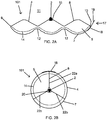
- the 'plug' according to the invention has the form of a so called plug (see figures 1B, 1C , 2B and 3B ), but in the first shape the 'plug' according to the invention actually does not have the form of a plug, but the form is more like a strip shaped configuration (see figures 1A , 2A and 3A ).
- the invented device is therefore indicated as 'a body for cultivation of plants'.
- the body 1, 101, 201 comprises a growing medium.
- Growing media for a rooting plug are well known in the prior art. Basically all growing media known in the prior art or to be developed in future can be used in a body 1, 101, 201 according to the invention, provided it allows transformation from the first shape into the second shape as required according to the invention.
- a growing medium suitable for use in the body according to the invention a medium comprising organic and/or non-organic fibres - which might optionally be bonded with a binder, like a polymer binder - can be mentioned.
- 101, 201 for the body 1, 101, 201 according to the invention one might use a growing medium of melt blown PLA fibres or a growing medium of peat and/or coconut fibres bonded with a polymer binder.
- a growing medium of polymer bonded peat is mentioned, which is used amongst others in the Flexi-plug 72R of Grow-Tech LLC, South Portland, ME, USA.
- a growing medium based on melt blown PLA fibres is mentioned, as is used in BioStrate also a product of Grow-Tech LLC, South Portland, ME, USA.
- the body 1, 101, 201 can be an integral part made solely from a growing medium, but it can also contain other parts. For example it might be made from two or more parts, interconnected by a flexible strip material (like the strip 18 of the closure mechanism 17 as described in relation to the embodiment of figure 2 ) allowing the transformation from the first shape into the second shape.
- a flexible strip material like the strip 18 of the closure mechanism 17 as described in relation to the embodiment of figure 2
- the body 1, 101, 201 for cultivation of a plant 2 has an external surface 4 forming the outer surface of the body 1, 101, 201.
- the external surface 4 of the body 1, 101, 201 consists of 4 surface parts together defining the external surface 4. These surface parts are: an upper surface part 5, a lower surface part 6 opposite to the upper surface part 5, an outer surface part 7, and an inner surface part 8 opposite the outer surface part 7.
- the body 1, 101, 201 further has a longitudinal axis 3 (only shown in fig. 1C , but also present in the embodiments of fig. 2 and 3 ).
- a longitudinal axis 3 (only shown in fig. 1C , but also present in the embodiments of fig. 2 and 3 ).
- figure 1C only shows the imaginary parts of the longitudinal axis extending outside the body, the part of the longitudinal axis 3 extending inside the body 3 is not shown for clarity reasons, but it will be clear that inner part of the longitudinal axis 3 extends from the upper surface part 5 - starting at the lower end of the upper part of the longitudinal axis 3 as shown in figure 1C - through the body 1, 101, 201 to the lower surface part 6 - ending at the upper end of the lower part of the longitudinal axis 3 as shown in figure 1C .
- the longitudinal axis 3 extends from the upper surface part 5 to the lower surface part 6. Viewed in the direction of the longitudinal axis, the inner surface part 8 and outer surface part 7 each extend from the upper surface part 5 to the lower surface part 6. Further the inner surface part 8 and outer surface part 7 each have two opposing longitudinal sides extending in the direction of the longitudinal axis 3. One longitudinal side of the inner surface part 8 and one longitudinal side of the outer surface part 7 are connected in a first transition zone 9 to form a continuous transition from the inner surface part 8 to the outer surface part 7. Similar, the other longitudinal side of the inner surface part 8 and the other longitudinal side of the outer surface part 7 are connected in a second transition zone 10 to form a continuous transition from the inner surface part 8 to the outer surface part 7. The inner surface part 8 fades so to say into the outer surface part 7 at the locations of the transition zones 9 and 10.
- the body 1, 101, 201 is transformable from a first shape shown in fig. 1A , 2A and fig 3A to a second shape shown in fig. 1B, 1C , 2B and 3B .
- the outline of the second shape is, viewed in a plane transverse to the longitudinal axis 3 fully determined by the outer surface part 7.
- the inner surface part 8 is completely embedded within the body 1, 101, 201 and inside the outer surface part 7.
- the body 1, 101, 201 is in an unfolded state such that the inner surface part 8 is exposed to the surrounding 11.
- Exposed to the surrounding means that it is freely accessible for a plant part with/without root structure, so that the plant part is not hindered by a small passage through which it is to be passed.
- exposed means, in the first and second embodiment, effectively that the body is in a kind of extended/outstretched configuration.
- the body 1, 101, 201 In the first shape/unfolded state, the body 1, 101, 201 as shown in the figures 1A , 2A and 3A is in a relieved state in which it remains as from itself.
- the body 1, 101, 201 does not close automatically, neither is there any tendency to transform by itself in the direction of the second shape. This facilitates easy placing plants, seeds, rooted plant parts etcetera in/on the body. It is however noted that according to another embodiment some bias might be present in the body 1, 101, 201 in order to assist in closing the body from the first to the second shape.
- the body is in its second shape folded up such that the inner surface part 8 is folded up onto itself.
- a small cavity 20 might remain.
- the inner surface part 8 is folded against itself at two or more sides of the cavity, i.e. it is folded into contact with itself at two or more sides of the cavity 20.
- Worded more in general - covering for example the situation that there is no cavity in the centre - the inner surface part 8 is folded against itself at two or more sides of the centre of the plug shaped body 1, 101, 201, i.e. it is folded into contact with itself at two or more sides of the centre of the plug shaped body 1, 101, 201.
- the body 1 has one bending zone 12 which is more flexible , especially thinner, than the adjacent zones of the body 1 in order to facilitate folding up of the body from the first to the second shape.
- a transverse axis 14 of the body 1,101, 201 is defined as: extending through the body 1, 101, 201 from the first transition zone 9 to the second transition zone 10; having, when the body 1, 101, 201 is in the first shape, an elongated line shaped configuration (which might be straight or curved) see fig. 1A , 2A and 3A , and having, when the body 1, 101, 201 is in the second shape, a ring shaped configuration, see fig. 1B , 2B and 3B .
- the inner surface part 8 has a profiled configuration allowing nesting or interlocking of the inner surface part with itself. This prevents shifting of segments of the inner surface part with respect to each other.
- the inner surface part 8 is profiled in such a manner that in the second shape a channel 20 is formed near the centre of the plug shaped body 1, 101, 201.
- the cavity is, in the second shape of the body, a channel 20 extending from the upper surface part 5 to the lower surface part 6. It is however to be noted that, within the scope of the invention as defined by the claims, it is very well conceivable that the cavity is just a cavity fully enclosed by the body, i.e. not being open towards the upper surface part or lower surface part.
- the cavity can be the result of a recess 15 formed in the inner surface part.
- the cavity can also be the result of profiling the inner surface part 8 at two locations, which, when the body is in the second shape, lie opposite each other.
- the inner surface part 8 of the body 1, 101, 201 when in its second shape, is at two or more sides of the centre/longitudinal axis 3 of the plug folded into contact with itself. In the first embodiment of figure 1 , this is at two opposing sides.
- the inner surface part 8 can be provided with a recess (no. 15 in fig. 2A and 3A ) and/or with an abutment (no. 16 in fig. 1A and 1B ).
- the body 1 can be maintained in its second shape by placing it in a cage 21 or in the plug hole of a so called plug tray.
- the body 101 can be maintained in its second shape by means of a closure mechanism 17, which in case of the embodiment of fig. 2 has the form of a strip 18 of flexible material, which strip 18 is provided with an adhesive 19 allowing the free part of the strip of fig. 1A to be adhered to the outer surface part 7, as shown in fig. 2B .
- the closure mechanism 17 of figure 2 or any other closure mechanism 17 can also be applied to the embodiment of fig. 1 or fig. 3 .
- a cage similar to the cage 21 in fig. 1C can also be used with the embodiments of fig. 2 and 3 .
Landscapes
- Life Sciences & Earth Sciences (AREA)
- Environmental Sciences (AREA)
- Cultivation Receptacles Or Flower-Pots, Or Pots For Seedlings (AREA)
Claims (11)
- Corps de milieu de croissance (1 ; 101 ; 201) pour la culture d'une plante (2) ;
dans lequel le corps (1 ; 101 ; 201) possède un axe longitudinal (3) et une surface externe (4) ; dans lequel la surface externe (4) est définie par :- une partie de surface supérieure (5) ;- une partie de surface inférieure (6) opposée à la partie de surface supérieure (5) ;- une partie de surface externe (7) ; et- une partie de surface interne (8) opposée à la partie de surface externe (7) ;dans lequel l'axe longitudinal (3) s'étend de la partie de surface supérieure (5) à la partie de surface inférieure (6) ;
dans lequel, visualisées dans la direction de l'axe longitudinal (3), les parties de surface interne (8) et externe (7) s'étendent chacune de la partie de surface supérieure (5) à la partie de surface inférieure (6) et possèdent chacune deux côtés longitudinaux opposés s'étendant dans la direction de l'axe longitudinal (3) ;
dans lequel, dans une première zone de transition (9), l'un dit côté longitudinal de la partie de surface interne (8) est relié à l'un dit côté longitudinal de la partie de surface externe (7) et, dans une seconde zone de transition (10), l'autre dit côté longitudinal de la partie de surface interne (8) est relié à l'autre dit côté longitudinal de la partie de surface externe (7) ;
dans lequel le corps (1 ; 101 ; 201) est apte à être transformé d'une première forme en une seconde forme ;
dans lequel, visualisée dans un plan transversal à l'axe longitudinal (3), le contour de la seconde forme est déterminé par la partie de surface externe (7) ;
dans lequel, dans la première forme, le corps (1 ; 101 ; 201) est déplié de sorte que la partie de surface interne (8) soit exposée vers l'environnement (11) ;
dans lequel, dans la seconde forme, le corps (1 ; 101 ; 201) est replié de sorte que la partie de surface interne (8) soit repliée sur elle-même ;
dans lequel le milieu de croissance comprend des fibres ou un matériau particulaire ;
dans lequel les fibres ou le matériau particulaire sont liés et en ce que le corps de milieu de croissance est un corps dimensionnellement stable ;
dans lequel un axe transversal (14) du corps (1 ; 101 ; 201) est défini comme :- s'étendant, à travers le corps (1 ; 101 ; 201), de la première zone de transition (9) à la seconde zone de transition (10),- ayant, lorsque le corps (1 ; 101 ; 201) est dans la première forme, une configuration en forme de ligne allongée, et- ayant, lorsque le corps (1 ; 101 ; 201) est dans la seconde forme, une configuration en forme d'anneau ; etdans lequel, visualisée dans la direction de l'axe transversal (14), la partie de surface interne (8) possède une configuration profilée permettant ledit repliement sur elle-même ;
dans lequel le corps (1 ; 101 ; 201) possède au moins une zone de courbure (12) s'étendant de la partie de surface supérieure (5) à la partie de surface inférieure (6), l'au moins une zone de courbure (12) étant plus souple que les zones adjacentes du corps (1 ; 101 ; 201) pour faciliter le repliement du corps (1 ; 101 ; 201) de la première forme à la seconde forme ;
dans lequel la configuration profilée est conçue pour fournir, lorsque le corps (1 ; 101 ; 201) est dans la seconde forme, un emboîtement de la partie de surface interne (8) avec elle-même, et caractérisé en ce que ledit emboîtement est tel que, dans la seconde forme du corps (1 ; 101 ; 201), la partie de surface interne (8) s'imbrique avec elle-même de sorte qu'un décalage de segments de la partie de surface interne (8) les uns par rapport aux autres est empêché. - Corps (1 ; 101 ; 201) selon la revendication 1, dans lequel la partie de surface interne (8) est munie d'un organe de positionnement, tel qu'un évidement (15) et/ou un bord de butée (16), et dans lequel, visualisé dans un plan transversal à l'axe longitudinal (3) et lorsque le corps (1 ; 101 ; 201) est dans sa seconde forme, l'organe de positionnement (13, 15, 16) est de préférence situé au centre du corps (1 ; 101 ; 201).
- Corps (1 ; 101 ; 201) selon la revendication 1 ou la revendication 2, dans lequel la configuration profilée de la partie de surface interne (8) est telle que, dans la seconde forme du corps (1 ; 101 ; 201), une cavité (13) est formée entre la partie de surface interne (8), laquelle cavité (13) est, visualisée dans une direction circonférentielle autour de l'axe longitudinal (3), fermée de toutes parts par la partie de surface interne (8).
- Corps (1 ; 101 ; 201) selon la revendication 3,- dans lequel, visualisée dans un plan transversal à l'axe longitudinal (3) et lorsque le corps (1 ; 101 ; 201) est dans sa seconde forme, la cavité (13) est située au centre du corps (1 ; 101 ; 201) ;
et/ou- dans lequel, lorsque le corps (1 ; 101 ; 201) est dans la seconde forme, la cavité (13) comprend un canal (20) s'étendant à partir de la partie de surface supérieure (5) dans la direction de l'axe longitudinal (3) jusqu'à l'intérieur du corps (1 ; 101 ; 201), ledit canal (20) s'étendant facultativement jusqu'à la partie de surface inférieure (6) ;
et/ou- dans lequel la cavité fournit l'organe de positionnement selon l'une quelconque des revendications 3 à 4. - Corps (1 ; 101 ; 201) selon l'une des revendications précédentes,- dans lequel la partie de surface externe (7) est essentiellement lisse ;
et/ou- dans lequel, lorsque le corps (1 ; 101 ; 201) est dans la seconde forme et visualisé dans un plan transversal à l'axe longitudinal (3), le corps (1 ; 101 ; 201) possède une section transversale ronde, ovale, rectangulaire ou triangulaire ;
et/ou- dans lequel, lorsque le corps (1 ; 101 ; 201) est dans la première forme et visualisé dans une direction perpendiculaire à l'axe longitudinal (3), le corps (1 ; 101 ; 201) possède une configuration étendue. - Corps (1 ; 101 ; 201) selon l'une des revendications précédentes,- dans lequel les fibres ou le matériau particulaire sont liés avec un liant ;
ou- dans lequel le milieu de croissance comprend des fibres organiques et/ou non organiques liées avec un liant, tel qu'un liant polymère ;
ou- dans lequel le milieu de croissance comprend des fibres d'acide polylactique, PLA, soufflées par fusion. - Corps (1 ; 101 ; 201) selon l'une des revendications précédentes, dans lequel le corps (1 ; 101 ; 201) est muni d'un mécanisme de fermeture (17) pour fixer le corps (1 ; 101 ; 201) dans sa seconde forme.
- Corps (1 ; 101 ; 201) selon l'une des revendications précédentes, dans lequel le corps est dans un état relâché lorsqu'il est dans sa première forme.
- Ensemble comprenant :- un corps (1 ; 101 ; 201) selon l'une des revendications précédentes dans sa seconde forme ; et- une tige de plante (2) au sein de la partie de surface interne (8) repliée sur elle-même.
- Procédé d'agencement d'une partie d'une plante (2), telle qu'une graine, une bouture ou une bouture pré-enracinée, dans un bouchon d'enracinement, dans lequel le procédé comprend les étapes de :- la fourniture d'un corps (1 ; 101 ; 201) selon l'une des revendications 1 à 8 dans sa première forme ;- le placement d'une dite partie d'une plante (2) sur la partie de surface interne (8) du corps (1 ; 101 ; 201) ; et- par la suite, le repliement du corps (1 ; 101 ; 201) de sa première forme vers sa seconde forme.
- Procédé selon la revendication 10, comprenant en outre l'étape de placement du corps replié (1 ; 101 ; 201) avec ladite partie d'une plante (2) au sein de la partie de surface interne (8), dans une cavité de bouchon (13) d'un plateau de plante (2).
Applications Claiming Priority (1)
| Application Number | Priority Date | Filing Date | Title |
|---|---|---|---|
| NL2013545A NL2013545B1 (en) | 2014-09-29 | 2014-09-29 | Body for cultivation of a plant. |
Publications (2)
| Publication Number | Publication Date |
|---|---|
| EP3000314A1 EP3000314A1 (fr) | 2016-03-30 |
| EP3000314B1 true EP3000314B1 (fr) | 2021-04-07 |
Family
ID=51947440
Family Applications (1)
| Application Number | Title | Priority Date | Filing Date |
|---|---|---|---|
| EP15187387.4A Active EP3000314B1 (fr) | 2014-09-29 | 2015-09-29 | Corps pour la culture d'une plante |
Country Status (4)
| Country | Link |
|---|---|
| US (1) | US20160088803A1 (fr) |
| EP (1) | EP3000314B1 (fr) |
| CA (1) | CA2875091A1 (fr) |
| NL (1) | NL2013545B1 (fr) |
Families Citing this family (5)
| Publication number | Priority date | Publication date | Assignee | Title |
|---|---|---|---|---|
| NL2018817B1 (nl) * | 2017-05-01 | 2018-11-09 | Besgrow Europe B V | Houder met substraat en werkwijze voor het cultiveren van een plant, en gebruik van een dergelijke houder |
| NL2018818B3 (en) * | 2017-05-01 | 2022-08-30 | Duemmen Group Bv | A rooting plug, a tray or pot and a method |
| NL2020979B1 (en) * | 2018-05-24 | 2019-12-02 | Duemmen Group Bv | A rooting plug structure and a method |
| DE102022123425B3 (de) * | 2022-09-14 | 2024-01-25 | Tilt Industries GmbH | Haltevorrichtung für mindestens ein Saatkorn und eine daraus wachsende Pflanze |
| US20250000038A1 (en) * | 2023-06-29 | 2025-01-02 | Profile Products Llc | Orchid propagation medium |
Family Cites Families (57)
| Publication number | Priority date | Publication date | Assignee | Title |
|---|---|---|---|---|
| US600344A (en) * | 1898-03-08 | Calendar | ||
| US1031713A (en) * | 1911-08-05 | 1912-07-09 | Charles Kreiling | Transplanting-pot. |
| US1936988A (en) * | 1933-05-09 | 1933-11-28 | Ralph B Otwell | Planting plan anchoring and embryo plant planting cartridge |
| US2140996A (en) * | 1936-09-15 | 1938-12-20 | Marathon Paper Mills Co | Container |
| US2215887A (en) * | 1937-05-04 | 1940-09-24 | Johns Manville | Method of operating mineral wool furnace |
| US2240599A (en) * | 1937-07-06 | 1941-05-06 | Universal Paper Products Compa | Container |
| US2572571A (en) * | 1948-07-29 | 1951-10-23 | Monsanto Chemicals | Stabilized vinyl chloride resins |
| US2656969A (en) * | 1950-07-26 | 1953-10-27 | John D Kvasnok | Frusto-conical container |
| US2796700A (en) * | 1953-09-14 | 1957-06-25 | Harry B Katz | Transplanting bag for nursery stock |
| US2833074A (en) * | 1955-08-10 | 1958-05-06 | Nicholas G Jannes | Pop-up display |
| US2968124A (en) * | 1957-05-10 | 1961-01-17 | Milo G Coplen | Plant container |
| US3132791A (en) * | 1961-11-13 | 1964-05-12 | Kenneth B Haysler | Flower pot |
| FR1411594A (fr) * | 1964-10-13 | 1965-09-17 | Production Grainiere Le Paysan | Dispositif noctifère et contrôleur de la poussée germinative d'une plante bulbeuse |
| US3306518A (en) * | 1965-06-30 | 1967-02-28 | Thomas K Connellan | Plastic container for plants |
| US3768720A (en) * | 1970-07-15 | 1973-10-30 | P Bundy | Flat foldable carton having a supported intermediate tray |
| US3992810A (en) * | 1974-06-05 | 1976-11-23 | Lakeland Enterprises, Inc. | Seedling tray |
| US3901431A (en) * | 1974-08-19 | 1975-08-26 | Int Paper Co | Cylindrical leak-resistant, thermoplastic coated, paperboard container |
| FR2416643A1 (fr) * | 1978-02-09 | 1979-09-07 | Foret Cellulose | Mottes de culture |
| US4166568A (en) * | 1978-06-19 | 1979-09-04 | Swan Walter B | Polygonal container |
| US4347686A (en) * | 1978-06-28 | 1982-09-07 | Canadian Patents & Development Limited | Fin-stabilized container of foldable sheet material |
| US4216622A (en) * | 1978-09-19 | 1980-08-12 | Hackney Howard U Jr | Plant container |
| US4223480A (en) * | 1978-11-01 | 1980-09-23 | Welty Gary A | Potted plant transplant liner |
| US4209092A (en) * | 1978-12-26 | 1980-06-24 | Jackson & Perkins Co. | Plant container |
| US4418497A (en) * | 1982-05-07 | 1983-12-06 | Mastriano Michael D | Combination greeting card, ornament and seed germination box |
| DK306485A (da) * | 1984-07-05 | 1986-01-06 | Challet Heraut Creations | Dyrkningssubstrat til planteceller, -vaev, -organer og hele planter |
| US4726468A (en) * | 1985-03-11 | 1988-02-23 | Chicago Corrugated Box Co. | Stabilizer box with variable opening |
| DE3883219T2 (de) * | 1988-05-14 | 1993-11-25 | Esu Oh Giken Co | Methode zum Herstellen von unter Druck getrockenete Pflanzenaufweisenden Gegenständen. |
| US5099608A (en) * | 1990-05-24 | 1992-03-31 | Casey Forrest R | Potted plant removal apparatus |
| US5054235A (en) * | 1990-08-24 | 1991-10-08 | David Pilz | Nursery plant containers |
| US5241783A (en) * | 1990-08-30 | 1993-09-07 | Krueger Scott D | Apparatus and process for growing plants |
| DE9202149U1 (de) * | 1992-02-19 | 1992-06-25 | Meurer Druck und Carton GmbH, 7760 Radolfzell | Vorrichtung zur Aufnahme und zum Transport von Pflanzen |
| FR2693079B1 (fr) * | 1992-07-01 | 1994-08-12 | Franclet Bore | Procédé de fabrication de mottes de culture destinées à être utilisées en pépinières. |
| US5293715A (en) * | 1992-12-04 | 1994-03-15 | Rita Kaz | Reversible dual-purpose self-standing pot cover |
| DE4244399C2 (de) * | 1992-12-29 | 1995-01-19 | Thomas Von Garrel | Faltbarer Topf zur Aufnahme von manuell oder maschinell einzusetzenden Pflanzen |
| US5359809A (en) * | 1993-06-17 | 1994-11-01 | Johnson Floyd L | Reusable pot for receiving a tree root ball and facilitating transport, handling and planting thereof |
| FR2715919B1 (fr) * | 1994-02-04 | 1996-05-31 | Marc Miquel | Conteneur biodégradable de grande taille, matériau et plants associés. |
| US5752649A (en) * | 1995-03-30 | 1998-05-19 | Southpac Trust International, Inc. | Self-erecting container with liner |
| JP3051345B2 (ja) * | 1995-09-19 | 2000-06-12 | みかど化工株式会社 | 植物育成方法 |
| US5676274A (en) * | 1996-03-27 | 1997-10-14 | Euromart Media International Inc. | Rollable storage device having multiple compartments |
| US6286252B1 (en) * | 1998-05-29 | 2001-09-11 | O'neal Daniel J. | Delivery system for horticultural agents |
| US6167653B1 (en) * | 1998-06-22 | 2001-01-02 | Jan M. Van Den Kieboom | Combination floral product and display container imprinted wrap around message sleeve on floral product and display container |
| US6371363B1 (en) * | 1999-01-26 | 2002-04-16 | Inland Paperboard And Packaging, Inc. | Bottom structure for collapsible container |
| DE29906386U1 (de) * | 1999-04-10 | 1999-06-17 | Christian Heinrich Sandler GmbH & Co. KG, 95126 Schwarzenbach a d Saale | Anzuchtkörper |
| AUPQ402999A0 (en) * | 1999-11-12 | 1999-12-09 | Trentcom Australia Pty Ltd | Improvements in or relating to growth containers |
| US20030155410A1 (en) * | 2001-12-10 | 2003-08-21 | Cozens Daphne Lyn | Transportation and display container |
| US6745514B1 (en) * | 2002-02-11 | 2004-06-08 | Brian Myrland | Container for shipping and/or display of flora |
| US6834792B1 (en) * | 2002-10-16 | 2004-12-28 | Plastic Systems, Inc. | Interlocking container |
| US20080078118A1 (en) * | 2003-11-17 | 2008-04-03 | Aerogrow International, Inc. | Master gardener baskets and methods for growing plants |
| US20090173002A1 (en) * | 2005-08-01 | 2009-07-09 | Plihal Clark P | Transplanting method and apparatus |
| USD547675S1 (en) * | 2005-08-02 | 2007-07-31 | Ct Pack S.R.L. | Ice cream wrapper |
| US7584855B2 (en) * | 2006-12-15 | 2009-09-08 | Alliance Packaging, Llc | Container and method for tie-less storage and transport of secured contents |
| WO2009015352A1 (fr) * | 2007-07-25 | 2009-01-29 | Ball Horticultural Company | Contenant sans fond pour plante |
| US20120137581A1 (en) * | 2009-08-07 | 2012-06-07 | Nuplant Pty Ltd | Plantlet handling system |
| US8329268B2 (en) * | 2009-12-07 | 2012-12-11 | Sonoco Development, Inc. | Paper-based plant pot, and blank for making same |
| NL2007469C2 (en) * | 2011-09-26 | 2013-03-28 | Max Roots B V | A rooting plug, a tray and a method. |
| US20130152466A1 (en) * | 2011-12-16 | 2013-06-20 | Velcro Industries B.V. | Convertible planting containers |
| US9010020B1 (en) * | 2014-07-10 | 2015-04-21 | Judith Ann Slusher | Plant container assembly and method |
-
2014
- 2014-09-29 NL NL2013545A patent/NL2013545B1/en not_active IP Right Cessation
- 2014-12-15 CA CA2875091A patent/CA2875091A1/fr not_active Abandoned
-
2015
- 2015-01-08 US US14/592,625 patent/US20160088803A1/en not_active Abandoned
- 2015-09-29 EP EP15187387.4A patent/EP3000314B1/fr active Active
Non-Patent Citations (1)
| Title |
|---|
| None * |
Also Published As
| Publication number | Publication date |
|---|---|
| EP3000314A1 (fr) | 2016-03-30 |
| CA2875091A1 (fr) | 2016-03-29 |
| US20160088803A1 (en) | 2016-03-31 |
| NL2013545B1 (en) | 2016-09-29 |
Similar Documents
| Publication | Publication Date | Title |
|---|---|---|
| EP3000314A1 (fr) | Corps pour la culture d'une plante | |
| US20180084739A1 (en) | Enclosing vegetative sheath | |
| JP6424304B2 (ja) | 植栽用具 | |
| KR102144743B1 (ko) | 다단 수경재배용 재배조 | |
| JP2008502357A (ja) | きゅうりやなすなどの生育栽培器 | |
| WO2008098724A1 (fr) | Pot de culture | |
| JP3154908U (ja) | 苗木育成用保護具 | |
| JP2009261324A (ja) | 作物の栽培・収穫方法および作物栽培用テープ | |
| KR20160022501A (ko) | 조림용 묘목의 뿌리분 형성장치 및 이를 이용한 뿌리분 형성방법 | |
| JP2006246757A (ja) | 緑化工法および在来多年生草本類による緑化構造 | |
| JP2009195159A (ja) | 苗木ポット | |
| JP4063809B2 (ja) | 園芸用簡易鉢 | |
| KR101812550B1 (ko) | 재배 상자 | |
| JP2012024024A (ja) | 交雑防止または交差防止用の部材および植物栽培装置ならびに植物栽培方法。 | |
| JP2009296917A (ja) | 断熱栽培方法 | |
| JP4116023B2 (ja) | 育苗ポット及び苗床 | |
| JP3114416U (ja) | 植栽用ポット | |
| KR200459024Y1 (ko) | 필름형 멀치 | |
| JP3074673U (ja) | 育苗・深植え移植容器 | |
| CN208891293U (zh) | 架高种植装置 | |
| JP2005034087A (ja) | 野菜、果物等の基部土被覆板 | |
| JP4838909B1 (ja) | マルチ栽培用の補助器具 | |
| JP5574360B2 (ja) | 育苗容器 | |
| JP3171627U (ja) | 内鉢、植木鉢 | |
| JP4849474B2 (ja) | 播種構造及びその構造に使用する植栽パック |
Legal Events
| Date | Code | Title | Description |
|---|---|---|---|
| PUAI | Public reference made under article 153(3) epc to a published international application that has entered the european phase |
Free format text: ORIGINAL CODE: 0009012 |
|
| AK | Designated contracting states |
Kind code of ref document: A1 Designated state(s): AL AT BE BG CH CY CZ DE DK EE ES FI FR GB GR HR HU IE IS IT LI LT LU LV MC MK MT NL NO PL PT RO RS SE SI SK SM TR |
|
| AX | Request for extension of the european patent |
Extension state: BA ME |
|
| 17P | Request for examination filed |
Effective date: 20160929 |
|
| RBV | Designated contracting states (corrected) |
Designated state(s): AL AT BE BG CH CY CZ DE DK EE ES FI FR GB GR HR HU IE IS IT LI LT LU LV MC MK MT NL NO PL PT RO RS SE SI SK SM TR |
|
| R17P | Request for examination filed (corrected) |
Effective date: 20160929 |
|
| R17P | Request for examination filed (corrected) |
Effective date: 20160929 |
|
| RAP1 | Party data changed (applicant data changed or rights of an application transferred) |
Owner name: GROW TECH, INC. |
|
| RAP1 | Party data changed (applicant data changed or rights of an application transferred) |
Owner name: DUEMMEN GROUP B.V. |
|
| STAA | Information on the status of an ep patent application or granted ep patent |
Free format text: STATUS: EXAMINATION IS IN PROGRESS |
|
| 17Q | First examination report despatched |
Effective date: 20200706 |
|
| REG | Reference to a national code |
Ref country code: DE Ref legal event code: R079 Ref document number: 602015067693 Country of ref document: DE Free format text: PREVIOUS MAIN CLASS: A01G0009100000 Ipc: A01G0009029000 |
|
| GRAP | Despatch of communication of intention to grant a patent |
Free format text: ORIGINAL CODE: EPIDOSNIGR1 |
|
| STAA | Information on the status of an ep patent application or granted ep patent |
Free format text: STATUS: GRANT OF PATENT IS INTENDED |
|
| RIC1 | Information provided on ipc code assigned before grant |
Ipc: A01G 9/029 20180101AFI20201012BHEP |
|
| INTG | Intention to grant announced |
Effective date: 20201029 |
|
| GRAS | Grant fee paid |
Free format text: ORIGINAL CODE: EPIDOSNIGR3 |
|
| GRAA | (expected) grant |
Free format text: ORIGINAL CODE: 0009210 |
|
| STAA | Information on the status of an ep patent application or granted ep patent |
Free format text: STATUS: THE PATENT HAS BEEN GRANTED |
|
| AK | Designated contracting states |
Kind code of ref document: B1 Designated state(s): AL AT BE BG CH CY CZ DE DK EE ES FI FR GB GR HR HU IE IS IT LI LT LU LV MC MK MT NL NO PL PT RO RS SE SI SK SM TR |
|
| REG | Reference to a national code |
Ref country code: GB Ref legal event code: FG4D |
|
| REG | Reference to a national code |
Ref country code: CH Ref legal event code: EP Ref country code: AT Ref legal event code: REF Ref document number: 1378481 Country of ref document: AT Kind code of ref document: T Effective date: 20210415 |
|
| REG | Reference to a national code |
Ref country code: DE Ref legal event code: R096 Ref document number: 602015067693 Country of ref document: DE |
|
| REG | Reference to a national code |
Ref country code: IE Ref legal event code: FG4D |
|
| REG | Reference to a national code |
Ref country code: NL Ref legal event code: FP |
|
| REG | Reference to a national code |
Ref country code: LT Ref legal event code: MG9D |
|
| REG | Reference to a national code |
Ref country code: AT Ref legal event code: MK05 Ref document number: 1378481 Country of ref document: AT Kind code of ref document: T Effective date: 20210407 |
|
| PG25 | Lapsed in a contracting state [announced via postgrant information from national office to epo] |
Ref country code: HR Free format text: LAPSE BECAUSE OF FAILURE TO SUBMIT A TRANSLATION OF THE DESCRIPTION OR TO PAY THE FEE WITHIN THE PRESCRIBED TIME-LIMIT Effective date: 20210407 Ref country code: FI Free format text: LAPSE BECAUSE OF FAILURE TO SUBMIT A TRANSLATION OF THE DESCRIPTION OR TO PAY THE FEE WITHIN THE PRESCRIBED TIME-LIMIT Effective date: 20210407 Ref country code: LT Free format text: LAPSE BECAUSE OF FAILURE TO SUBMIT A TRANSLATION OF THE DESCRIPTION OR TO PAY THE FEE WITHIN THE PRESCRIBED TIME-LIMIT Effective date: 20210407 Ref country code: BG Free format text: LAPSE BECAUSE OF FAILURE TO SUBMIT A TRANSLATION OF THE DESCRIPTION OR TO PAY THE FEE WITHIN THE PRESCRIBED TIME-LIMIT Effective date: 20210707 Ref country code: AT Free format text: LAPSE BECAUSE OF FAILURE TO SUBMIT A TRANSLATION OF THE DESCRIPTION OR TO PAY THE FEE WITHIN THE PRESCRIBED TIME-LIMIT Effective date: 20210407 |
|
| PG25 | Lapsed in a contracting state [announced via postgrant information from national office to epo] |
Ref country code: LV Free format text: LAPSE BECAUSE OF FAILURE TO SUBMIT A TRANSLATION OF THE DESCRIPTION OR TO PAY THE FEE WITHIN THE PRESCRIBED TIME-LIMIT Effective date: 20210407 Ref country code: IS Free format text: LAPSE BECAUSE OF FAILURE TO SUBMIT A TRANSLATION OF THE DESCRIPTION OR TO PAY THE FEE WITHIN THE PRESCRIBED TIME-LIMIT Effective date: 20210807 Ref country code: GR Free format text: LAPSE BECAUSE OF FAILURE TO SUBMIT A TRANSLATION OF THE DESCRIPTION OR TO PAY THE FEE WITHIN THE PRESCRIBED TIME-LIMIT Effective date: 20210708 Ref country code: PL Free format text: LAPSE BECAUSE OF FAILURE TO SUBMIT A TRANSLATION OF THE DESCRIPTION OR TO PAY THE FEE WITHIN THE PRESCRIBED TIME-LIMIT Effective date: 20210407 Ref country code: NO Free format text: LAPSE BECAUSE OF FAILURE TO SUBMIT A TRANSLATION OF THE DESCRIPTION OR TO PAY THE FEE WITHIN THE PRESCRIBED TIME-LIMIT Effective date: 20210707 Ref country code: PT Free format text: LAPSE BECAUSE OF FAILURE TO SUBMIT A TRANSLATION OF THE DESCRIPTION OR TO PAY THE FEE WITHIN THE PRESCRIBED TIME-LIMIT Effective date: 20210809 Ref country code: ES Free format text: LAPSE BECAUSE OF FAILURE TO SUBMIT A TRANSLATION OF THE DESCRIPTION OR TO PAY THE FEE WITHIN THE PRESCRIBED TIME-LIMIT Effective date: 20210407 Ref country code: SE Free format text: LAPSE BECAUSE OF FAILURE TO SUBMIT A TRANSLATION OF THE DESCRIPTION OR TO PAY THE FEE WITHIN THE PRESCRIBED TIME-LIMIT Effective date: 20210407 Ref country code: RS Free format text: LAPSE BECAUSE OF FAILURE TO SUBMIT A TRANSLATION OF THE DESCRIPTION OR TO PAY THE FEE WITHIN THE PRESCRIBED TIME-LIMIT Effective date: 20210407 |
|
| REG | Reference to a national code |
Ref country code: DE Ref legal event code: R097 Ref document number: 602015067693 Country of ref document: DE |
|
| PG25 | Lapsed in a contracting state [announced via postgrant information from national office to epo] |
Ref country code: CZ Free format text: LAPSE BECAUSE OF FAILURE TO SUBMIT A TRANSLATION OF THE DESCRIPTION OR TO PAY THE FEE WITHIN THE PRESCRIBED TIME-LIMIT Effective date: 20210407 Ref country code: EE Free format text: LAPSE BECAUSE OF FAILURE TO SUBMIT A TRANSLATION OF THE DESCRIPTION OR TO PAY THE FEE WITHIN THE PRESCRIBED TIME-LIMIT Effective date: 20210407 Ref country code: DK Free format text: LAPSE BECAUSE OF FAILURE TO SUBMIT A TRANSLATION OF THE DESCRIPTION OR TO PAY THE FEE WITHIN THE PRESCRIBED TIME-LIMIT Effective date: 20210407 Ref country code: SM Free format text: LAPSE BECAUSE OF FAILURE TO SUBMIT A TRANSLATION OF THE DESCRIPTION OR TO PAY THE FEE WITHIN THE PRESCRIBED TIME-LIMIT Effective date: 20210407 Ref country code: SK Free format text: LAPSE BECAUSE OF FAILURE TO SUBMIT A TRANSLATION OF THE DESCRIPTION OR TO PAY THE FEE WITHIN THE PRESCRIBED TIME-LIMIT Effective date: 20210407 Ref country code: RO Free format text: LAPSE BECAUSE OF FAILURE TO SUBMIT A TRANSLATION OF THE DESCRIPTION OR TO PAY THE FEE WITHIN THE PRESCRIBED TIME-LIMIT Effective date: 20210407 |
|
| PLBE | No opposition filed within time limit |
Free format text: ORIGINAL CODE: 0009261 |
|
| STAA | Information on the status of an ep patent application or granted ep patent |
Free format text: STATUS: NO OPPOSITION FILED WITHIN TIME LIMIT |
|
| 26N | No opposition filed |
Effective date: 20220110 |
|
| REG | Reference to a national code |
Ref country code: CH Ref legal event code: PL |
|
| GBPC | Gb: european patent ceased through non-payment of renewal fee |
Effective date: 20210929 |
|
| PG25 | Lapsed in a contracting state [announced via postgrant information from national office to epo] |
Ref country code: IS Free format text: LAPSE BECAUSE OF FAILURE TO SUBMIT A TRANSLATION OF THE DESCRIPTION OR TO PAY THE FEE WITHIN THE PRESCRIBED TIME-LIMIT Effective date: 20210807 Ref country code: MC Free format text: LAPSE BECAUSE OF FAILURE TO SUBMIT A TRANSLATION OF THE DESCRIPTION OR TO PAY THE FEE WITHIN THE PRESCRIBED TIME-LIMIT Effective date: 20210407 Ref country code: AL Free format text: LAPSE BECAUSE OF FAILURE TO SUBMIT A TRANSLATION OF THE DESCRIPTION OR TO PAY THE FEE WITHIN THE PRESCRIBED TIME-LIMIT Effective date: 20210407 |
|
| PG25 | Lapsed in a contracting state [announced via postgrant information from national office to epo] |
Ref country code: LU Free format text: LAPSE BECAUSE OF NON-PAYMENT OF DUE FEES Effective date: 20210929 Ref country code: IT Free format text: LAPSE BECAUSE OF FAILURE TO SUBMIT A TRANSLATION OF THE DESCRIPTION OR TO PAY THE FEE WITHIN THE PRESCRIBED TIME-LIMIT Effective date: 20210407 Ref country code: IE Free format text: LAPSE BECAUSE OF NON-PAYMENT OF DUE FEES Effective date: 20210929 Ref country code: GB Free format text: LAPSE BECAUSE OF NON-PAYMENT OF DUE FEES Effective date: 20210929 Ref country code: FR Free format text: LAPSE BECAUSE OF NON-PAYMENT OF DUE FEES Effective date: 20210930 |
|
| PG25 | Lapsed in a contracting state [announced via postgrant information from national office to epo] |
Ref country code: LI Free format text: LAPSE BECAUSE OF NON-PAYMENT OF DUE FEES Effective date: 20210930 Ref country code: CH Free format text: LAPSE BECAUSE OF NON-PAYMENT OF DUE FEES Effective date: 20210930 |
|
| REG | Reference to a national code |
Ref country code: NL Ref legal event code: PD Owner name: PROFILE PRODUCTS LLC; US Free format text: DETAILS ASSIGNMENT: CHANGE OF OWNER(S), ASSIGNMENT; FORMER OWNER NAME: DUEMMEN GROUP B.V. Effective date: 20230414 |
|
| REG | Reference to a national code |
Ref country code: DE Ref legal event code: R081 Ref document number: 602015067693 Country of ref document: DE Owner name: PROFILE PRODUCTS LLC, BUFFALO GROVE, US Free format text: FORMER OWNER: DUEMMEN GROUP B.V., DE LIER, NL |
|
| PG25 | Lapsed in a contracting state [announced via postgrant information from national office to epo] |
Ref country code: HU Free format text: LAPSE BECAUSE OF FAILURE TO SUBMIT A TRANSLATION OF THE DESCRIPTION OR TO PAY THE FEE WITHIN THE PRESCRIBED TIME-LIMIT; INVALID AB INITIO Effective date: 20150929 |
|
| P01 | Opt-out of the competence of the unified patent court (upc) registered |
Effective date: 20230516 |
|
| PG25 | Lapsed in a contracting state [announced via postgrant information from national office to epo] |
Ref country code: CY Free format text: LAPSE BECAUSE OF FAILURE TO SUBMIT A TRANSLATION OF THE DESCRIPTION OR TO PAY THE FEE WITHIN THE PRESCRIBED TIME-LIMIT Effective date: 20210407 |
|
| REG | Reference to a national code |
Ref country code: BE Ref legal event code: PD Owner name: PROFILE PRODUCTS LLC; US Free format text: DETAILS ASSIGNMENT: CHANGE OF OWNER(S), ASSIGNMENT; FORMER OWNER NAME: DUEMMEN GROUP B.V. Effective date: 20230502 |
|
| PG25 | Lapsed in a contracting state [announced via postgrant information from national office to epo] |
Ref country code: MK Free format text: LAPSE BECAUSE OF FAILURE TO SUBMIT A TRANSLATION OF THE DESCRIPTION OR TO PAY THE FEE WITHIN THE PRESCRIBED TIME-LIMIT Effective date: 20210407 |
|
| PG25 | Lapsed in a contracting state [announced via postgrant information from national office to epo] |
Ref country code: TR Free format text: LAPSE BECAUSE OF FAILURE TO SUBMIT A TRANSLATION OF THE DESCRIPTION OR TO PAY THE FEE WITHIN THE PRESCRIBED TIME-LIMIT Effective date: 20210407 |
|
| PG25 | Lapsed in a contracting state [announced via postgrant information from national office to epo] |
Ref country code: MT Free format text: LAPSE BECAUSE OF FAILURE TO SUBMIT A TRANSLATION OF THE DESCRIPTION OR TO PAY THE FEE WITHIN THE PRESCRIBED TIME-LIMIT Effective date: 20210407 |
|
| PGFP | Annual fee paid to national office [announced via postgrant information from national office to epo] |
Ref country code: DE Payment date: 20250929 Year of fee payment: 11 |
|
| PGFP | Annual fee paid to national office [announced via postgrant information from national office to epo] |
Ref country code: NL Payment date: 20250926 Year of fee payment: 11 |
|
| PGFP | Annual fee paid to national office [announced via postgrant information from national office to epo] |
Ref country code: BE Payment date: 20250929 Year of fee payment: 11 |