EP3000514B1 - Yo-yo transformable - Google Patents
Yo-yo transformable Download PDFInfo
- Publication number
- EP3000514B1 EP3000514B1 EP15744843.2A EP15744843A EP3000514B1 EP 3000514 B1 EP3000514 B1 EP 3000514B1 EP 15744843 A EP15744843 A EP 15744843A EP 3000514 B1 EP3000514 B1 EP 3000514B1
- Authority
- EP
- European Patent Office
- Prior art keywords
- clamping
- rotators
- connecting shaft
- transformable
- disk
- Prior art date
- Legal status (The legal status is an assumption and is not a legal conclusion. Google has not performed a legal analysis and makes no representation as to the accuracy of the status listed.)
- Not-in-force
Links
Images



Classifications
-
- A—HUMAN NECESSITIES
- A63—SPORTS; GAMES; AMUSEMENTS
- A63H—TOYS, e.g. TOPS, DOLLS, HOOPS OR BUILDING BLOCKS
- A63H1/00—Tops
- A63H1/30—Climbing tops, e.g. Yo-Yo
Definitions
- the present invention relates to a yo-yo, in particular to a transformable yo-yo.
- yo-yos mainly consist of the following components: as the basic composition, two rotators and a connecting shaft for connecting the two rotators; a screw hole is formed in the middle of a back side of each of the rotators, threads are provided on two ends of the connecting shaft; and the screw hole and the threads work together to assemble a complete yo-yo.
- a yo-yo can only be assembled in one way, that is, such a yo-yo has only one form with no alterability, and is thus less fun.
- kids are more likely to lose interest in such a yo-yo. Should the kids desire a yo-yo of another form, they would have to buy a new one. When they have a new yo-yo, the older one will likely be discarded, which is a waste of resources.
- a transformable yo-yo having two forms, according to the preamble of claim 1, is disclosed in CN203724754U .
- An objective of the present invention is to provide a transformable yo-yo, capable of being mounted from both front and back sides and having two forms and persistent interestingness, and an arrangement of structural features improving the ease of operation.
- a yo-yo of the present invention has two different assembling forms, kids can transform a yo-yo to a different form according to their preferences, and the yo-yo in a different form also has different characteristics. As the characteristics are different, different tricky moves are possible. kids may play with a yo-yo in more varied ways and have more fun.
- the transformable yo-yo of the present invention which is an equivalence to two existing yo-yos, is more cost effective and can gain traction more easily among with kids.
- the clamping members are used as the connecting device, the transforming operation is simpler, easier, and faster, without getting in the way of the kids playing. Furthermore, such a connecting method contributes to low wear rate and thus effectively improves the service life of the yo-yo.
- This toy yo-yo is smartly designed, can offer variable assembly forms and novel ways to play, meets the needs and the curiosity of kids, and meanwhile riches ways of playing with the yo-yo, so that this yo-yo is very interesting.
- a transformable yo-yo including two rotators 1 and a connecting shaft 2 for connecting the two rotators 1, wherein a though hole 10, into which the connecting shaft 2 is inserted form two directions, is arranged in the middle of each of the rotators 1, and a connecting device, configured to connect and secure the connecting shaft 2, is arranged in the through hole 10; by moving the connecting device, the securing to the connecting shaft 2 can be released so that the rotators 1 are separated from the connecting shaft 2; the back sides of the two rotators 1 are oppositely connected to the connecting shaft 2, and connected and secured through the connecting device to assemble a yo-yo of a first form; and after releasing the securing, the front sides of the two rotators 1 are oppositely connected to the connecting shaft 2, and secured through the connecting device as well to assemble a yo-yo of a second form.
- a yo-yo has two different assembling forms
- kids can transform a yo-yo to a different form according to their preferences, and the yo-yo in a different form also has different characteristics. According to different characteristics, corresponding fancy operations may be made.
- kids may play with a yo-yo in more varied ways and become more interested.
- the transformable yo-yo of the present invention equivalently to two existing yo-yos, is cost effective and more easily to be popular with kids.
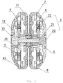
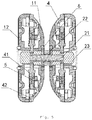
- the connecting device of this embodiment is a clamping structure which includes clamping sites arranged at the two ends of the connecting shaft 2 and elastic clamping members arranged in the rotators 1, and after inserting the connecting shaft 2 into the through hole 10 from the front side of each of the rotators 1 or from the back side of each of the rotators 1, the clamping sites on the connecting shaft 2 are clamped and secured with the clamping members in the rotators 1, automatically, as shown in Fig. 6 ; and by pressing the elastic clamping members to release the clamping between the elastic clamping members and the clamping sites of the connecting shaft 2, the rotators 1 are separated from the connecting shaft 2, as shown in Fig. 7 .
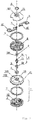
- the connecting shaft 2 of this embodiment includes a post 21 having threads at both ends thereof, a bearing 22 sleeved in the middle of the post 21, and two bushings 23 screwed on the threads at the both ends of the post 21; the clamping sites are formed at the front end of the bushing 23.
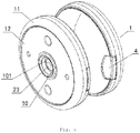
- Each of the rotators 1 of this embodiment includes a disk 11 and a shell 12, and the disk 11 is butt-jointed to the shell 12 and then connected and secured when screwed by screws; each of the elastic clamping members is arranged in the disk 11; a through hole 10, from which the bushing 23 is extended, is arranged in the middle of each of the disk 11 and the shell 12, the bushing 23 is inserted into the through hole 10 on the disk 11 to be connected to the clamping member to assemble the yo-yo of the first form, and the bushing 23 is inserted into the through hole 10 on the shell 12 to be connected to the clamping member to assemble the yo-yo of the second form.
- hexagonal hole seats 101 are arranged on inner sides of the through holes 10 on both the disk 11 and the shell 12, and correspondingly, rear ends of the bushings 23 are designed as hexagonal columns 231; and the hexagonal columns 231 and the hexagonal hole seats 101 work together to enable the rotators 1 to rotate along with the connecting shaft 2, synchronously.
- Each of the elastic clamping members of this embodiment includes a pair of -shaped clamping plates 4 and a compression spring 5 arranged at a front end of a front crossbar 41 of the clamping plate 4, and correspondingly, the clamping sites on the connecting shaft 2 are designed as circular grooves 3; the two clamping plates 4 work together to press a front end of the compression spring 5 of one clamping plate 4 onto a front edge of a rear crossbar 42 of the other clamping plate 4; hence, after the two clamping plates 4 are mounted into the disk 11 of the rotators 1, due to compression by the compression springs 5, rear edges of the front crossbars 41 of the two clamping plates 4 are clamped into the circular grooves 3 of the connecting shaft 2, thus realizing the purpose of fastening and securing, as shown in Fig.
- Two symmetrical through openings 8 are formed on side walls of both the disk 11 and the shell 12 of this embodiment, meanwhile, a mounting guide plate is provided in interior of the disk 11; the two clamping plates 4 are mounted in a direction of the through openings 8, and the rear ends of the rear crossbars 42 of the two clamping plates 4 are both extended from the through openings 8 of the rotators 1 to form two pressing ends; pressing the two pressing ends by two fingers so that the rear edges of the front crossbars 41 of the clamping plates 4 move to be relatively separated from each other, as a result, the relative distance between the rear edges of the front crossbars 41 of the clamping plates 4 becomes larger until the rear edges of the two front crossbars 41 extends from the circular 3; and at this moment, the rotators 1 are pulled outward by two fingers, simultaneously, to separate the rotators 1 from the connecting shaft 2; the operation of the other rotator 1 is the same as that mentioned above, as shown in Fig.
- circular grooves 102 are concavely arranged in positions, close to the through holes 10, on outer sides of both the disk 11 and the shell 12, and withdrawing rings 6 which facilitate the withdrawing of a string of yo-yo are arranged in the circular grooves 102.
- a balance weight ring 7 may be arranged in each of the rotator 1, and the balance weight ring 7 in this embodiment is mounted in the disk 11 of the rotator 1.
- the connecting device of this embodiment is also a clamping structure which includes clamping sites arranged at the two ends of the connecting shaft 2 and clamping members arranged in the rotators 1.
- the clamping members in the rotators 1 are not elastic, and after inserting the connecting shaft 2 into the through hole 10 from the front side of each of the rotators 1 or from the back side of each of the rotators 1, the clamping members are pushed inward by a hand to be clamped and secured with the clamping sites of the connecting shaft; and when the clamping is required to be released, the clamping members are required to be pulled outward by a hand so that the clamping members release the clamping to the clamping sites of the connecting shaft 2 thus to separate the rotators 1 from the connecting shaft 2.
- the connecting device of this embodiment is also a clamping structure.
- the clamping structure includes pin holes formed at both ends of the connecting shaft 2 and plug pins formed on the rotators 1; after inserting the connecting shaft 2 into the through hole 10 from the front side of each of the rotators 1 or from the back side of each of the rotators 1, and after aligning the pin holes with the positions of the plug pins, the plug pins are pushed inward into the pin holes by a hand in order to be clamped and secured therein; and when the clamping is required to be released, the plug pins are required to be pulled by a hand out from the pin holes of the connecting shaft thus to release the clamping.
- the rotators 1 separates from the connecting shaft 2.
- the connecting device of this example not part of the claimed invention is a screwing structure which includes internal threads arranged on the through hole 10 and external threads arranged at two ends of the connecting shaft 2, and the external threads of the connecting shaft 2 are inserted into the internal threads of the through hole 10 from the front side of each of the rotators 1 or from the back side of each of the rotators 1 so that the connecting shaft 2 connects and clamps to the rotators 1; and when the clamping is required to be released, directly rotating the rotators 1 may separate the rotators 1 from the connecting shaft 2.
Landscapes
- Toys (AREA)
- Clamps And Clips (AREA)
Claims (10)
- Yoyo transformable comprenant deux rotateurs (1) et un arbre de liaison (2) permettant de relier les deux rotateurs (1), un trou traversant (10) dans lequel l'arbre de liaison (2) est inséré à partir de deux directions étant prévu au milieu de chacun des rotateurs (1) et un dispositif de liaison, conçu pour relier et pour fixer l'arbre de liaison (2), est prévu dans le trou traversant (10) ; par déplacement du dispositif de liaison, la fixation à l'arbre de liaison (2) est libérée si bien que les rotateurs (1) sont séparés de l'arbre de liaison (2) ; les côtés arrière des deux rotateurs (1) sont reliés de manière opposée à l'arbre de liaison (2) et reliés et fixés par le dispositif de liaison pour assembler un yoyo d'une première forme ; et après la fixation, les côtés avant des deux rotateurs (1) sont reliés de manière opposée à l'arbre de liaison (2), et fixés par le biais du dispositif de liaison aussi pour assembler un yoyo d'une seconde forme ; caractérisé en ce que le dispositif de liaison est une structure de serrage comprenant des sites de serrage prévus aux deux extrémités de l'arbre de liaison (2) et des éléments de serrage prévus dans les rotateurs (1), et après l'insertion de l'arbre de liaison (2) dans le trou traversant (10) à partir du côté avant de chacun des rotateurs (1) ou à partir du côté arrière de chacun des rotateurs (1), les sites de serrage situés sur l'arbre de liaison (2) sont automatiquement serrés et fixés à l'aide des éléments de serrage dans les rotateurs (1) ; et l'arbre de liaison (2) comprenant une tige (21) comportant des filetages aux deux extrémités de la tige, un palier (22) emmanché au milieu de la tige (21) et deux douilles (23) vissées sur les filetages aux deux extrémités de la tige (21) ; et les sites de serrage étant formés à l'extrémité avant de la douille (23).
- Yoyo transformable selon la revendication 1, caractérisé en ce que les éléments de serrage présents dans les rotateurs (1) sont des éléments élastiques de serrage, et en appuyant sur les éléments élastiques de serrage pour libérer le serrage entre les éléments de serrage élastique et les sites de serrage de l'arbre de liaison (2), les rotateurs (1) sont séparés de l'arbre de liaison (2).
- Yoyo transformable selon la revendication 1, caractérisé en ce que les sites de serrage sont des sites à rainure annulaire (3) ou des trous d'épingle formés sur les douilles (23), et en correspondance, les éléments de serrage sont des plaques de serrage serrées dans les rainures annulaires (3) ou des épingles de bouchage insérées dans les trous d'épingle.
- Yoyo transformable selon la revendication 1, caractérisé en ce que chacun des rotateurs (1) comprend un disque (11) et une coque (12), et où le disque (11) est assemblé bout à bout à la coque (12) puis relié et fixé de manière serrée par des vis ; chacun des éléments de serrage est agencé dans le disque (11) ; et chacun de la douille (23) de l'arbre de liaison (2) s'étend dans le disque (11) alors que les sites de serrage situés sur la douille (23) sont serrés à l'aide des éléments de serrage.
- Yoyo transformable selon la revendication 4, caractérisé en ce qu'un trou traversant (10) à partir duquel la douille (23) est étendue, est agencée au milieu de chacun du disque (11) et de la coque (12) ; la douille (23) est insérée dans le trou traversant (10) sur le disque (11) pour être reliée à l'élément de serrage pour assembler le yoyo de la première forme ; et la douille (23) est insérée dans le trou traversant (10) sur la coque (12) pour être reliée à l'élément de serrage pour assembler le yoyo de la seconde forme.
- Yoyo transformable selon la revendication 5, caractérisé en ce que les sièges hexagonaux de trous (101) sont prévus sur des côtés intérieurs des trous traversants (10) à la fois sur le disque (11) et sur la coque (12) et en correspondance, les extrémités arrière des douilles (23) sont conçues sous forme de colonnes hexagonales (231) ; et les colonnes hexagonales (231) et les sièges hexagonaux de trous (101) travaillent ensemble pour permettre aux rotateurs (1) de tourner le long de l'arbre de liaison (2), de manière synchrone.
- Yoyo transformable selon la revendication 6, caractérisé en ce que les rainures circulaires (102) sont prévues de manière concave dans des positions, proches des trous traversants (10), sur des côtés extérieurs du disque (11) et de la coque (12), et des bagues de retrait 6, qui facilitent le retrait d'une ficelle de yoyo, sont prévues dans les rainures circulaires (102).
- Yoyo transformable selon la revendication 2, caractérisé en ce que chacun des éléments de serrage comprend une paire de plaques de serrage en forme de U (4) et un ressort de compression (5) prévu à une extrémité avant d'une barre transversale avant (41) de la plaque de serrage (4), et en correspondance, les sites de serrage situés sur l'arbre de liaison (2) sont conçus comme des rainures circulaires (3) ; les deux plaques de serrage (4) travaillent ensemble pour comprimer une extrémité avant du ressort de compression (5) d'une plaque de serrage (4) sur un bord avant d'une barre transversale arrière (42) de l'autre plaque de serrage (4) ; et après avoir monté les deux plaques de serrage (4) dans les rotateurs (1), sous l'effet de la compression par les ressorts de compression (5), des bords arrière des barres transversales avant (41) des deux plaques de serrage (4) sont serrées dans les rainures circulaires (3) de l'arbre de liaison (2), ce qui permet d'atteindre l'objectif de fixation et de fermeture.
- Yoyo transformable selon la revendication 8, caractérisé en ce que deux ouvertures traversantes symétriques (8) sont formées sur des parois latérales des rotateurs (1) ; les deux plaques de serrage (4) sont montées dans une direction des ouvertures traversantes (8) et les extrémités arrière des barres transversales arrière (42) des deux plaques de serrage (4) sont toutes les deux étendues à partir des ouvertures traversantes (8) des rotateurs (1) pour former deux extrémités de compression ; la compression des deux extrémités de compression par les doigts pour que les bords arrière des barres transversales avant (41) des plaques de serrage (4) se déplacent pour être relativement séparées l'une de l'autre, les plaques de serrage (4) libèrent le serrage vers la rainure circulaire (3), ce qui permet de réaliser la séparation des rotateurs (1) de l'arbre de liaison (2).
- Yoyo transformable selon la revendication 1, caractérisé en ce qu'une bague de poids d'équilibrage (7) est prévue dans chacun des rotateurs (1).
Applications Claiming Priority (2)
| Application Number | Priority Date | Filing Date | Title |
|---|---|---|---|
| CN201410368759.5A CN104288999B (zh) | 2014-07-30 | 2014-07-30 | 一种可变形的悠悠球 |
| PCT/CN2015/070946 WO2016015459A1 (fr) | 2014-07-30 | 2015-01-17 | Yo-yo transformable |
Publications (3)
| Publication Number | Publication Date |
|---|---|
| EP3000514A1 EP3000514A1 (fr) | 2016-03-30 |
| EP3000514A4 EP3000514A4 (fr) | 2016-10-26 |
| EP3000514B1 true EP3000514B1 (fr) | 2018-11-28 |
Family
ID=52309091
Family Applications (1)
| Application Number | Title | Priority Date | Filing Date |
|---|---|---|---|
| EP15744843.2A Not-in-force EP3000514B1 (fr) | 2014-07-30 | 2015-01-17 | Yo-yo transformable |
Country Status (15)
| Country | Link |
|---|---|
| US (1) | US9468858B2 (fr) |
| EP (1) | EP3000514B1 (fr) |
| JP (1) | JP6134447B2 (fr) |
| KR (1) | KR101770278B1 (fr) |
| CN (1) | CN104288999B (fr) |
| AU (1) | AU2015218448B2 (fr) |
| BR (1) | BR112015021541A2 (fr) |
| CA (1) | CA2899674C (fr) |
| ES (1) | ES2709825T3 (fr) |
| MX (1) | MX2015011608A (fr) |
| MY (1) | MY175117A (fr) |
| RU (1) | RU2620706C1 (fr) |
| SG (1) | SG11201509674PA (fr) |
| TR (1) | TR201901513T4 (fr) |
| WO (1) | WO2016015459A1 (fr) |
Families Citing this family (13)
| Publication number | Priority date | Publication date | Assignee | Title |
|---|---|---|---|---|
| JP4859206B2 (ja) | 2006-02-20 | 2012-01-25 | 株式会社セガ トイズ | 玩具 |
| USD809456S1 (en) * | 2016-03-18 | 2018-02-06 | Halo2Cloud, LLC | Power adapter |
| USD807825S1 (en) * | 2016-03-18 | 2018-01-16 | Halo2Cloud, LLC | Power adapter |
| USD807826S1 (en) * | 2016-03-18 | 2018-01-16 | Halo2Cloud, LLC | Combination power adapter and detachable battery |
| CN107537159B (zh) * | 2016-06-27 | 2023-06-20 | 奥飞娱乐股份有限公司 | 可方便拆卸功能配件的悠悠球 |
| CN106492466A (zh) * | 2016-12-12 | 2017-03-15 | 奥飞娱乐股份有限公司 | 一种可多形态多功能变化的悠悠球 |
| CN207153096U (zh) * | 2016-12-12 | 2018-03-30 | 奥飞娱乐股份有限公司 | 回旋球 |
| KR200489684Y1 (ko) * | 2019-04-25 | 2019-10-01 | 선우윤 | 요요 완구 |
| KR102394611B1 (ko) | 2020-09-07 | 2022-05-06 | 정재일 | 죽방울 놀이기구 |
| US11712636B1 (en) | 2022-08-12 | 2023-08-01 | Spin Master Ltd. | Transformable toy |
| US12576341B2 (en) | 2022-08-12 | 2026-03-17 | Spin Master Ltd. | Transformable toy |
| DE102022131044A1 (de) * | 2022-11-23 | 2024-05-23 | Explicatis Gmbh | Seilrolle, Seilrollensystem und Verfahren zum Aufwickeln und Abwickeln eines Zugelements |
| JP1780874S (ja) * | 2024-01-09 | 2024-09-27 | ヨーヨー |
Family Cites Families (20)
| Publication number | Priority date | Publication date | Assignee | Title |
|---|---|---|---|---|
| BE391982A (fr) * | ||||
| US4332102A (en) * | 1980-10-27 | 1982-06-01 | Caffrey Michael S | Superior performance yo-yo |
| JPH11137859A (ja) * | 1997-11-07 | 1999-05-25 | Bandai Co Ltd | ヨーヨー玩具 |
| US6053796A (en) * | 1998-07-02 | 2000-04-25 | Lisa Lin | Yo-yo |
| JP3236822B2 (ja) * | 1998-07-24 | 2001-12-10 | 松下電器産業株式会社 | ヨーヨー |
| DE29815344U1 (de) * | 1998-08-27 | 1998-11-12 | Hoo In Trading Co., Seoul/Soul | Jo-Jo |
| US6196891B1 (en) * | 1999-11-19 | 2001-03-06 | Flambeau Products Corporation | Yo-yo including adjustable weight system |
| CN2426753Y (zh) * | 2000-01-10 | 2001-04-18 | 蔡东青 | 一种组装式悠悠球 |
| US6354905B1 (en) * | 2000-02-08 | 2002-03-12 | Flambeau Products Corporation | Yo-yo having adjustable clutch |
| JP2003135859A (ja) * | 2001-10-31 | 2003-05-13 | Tomy Co Ltd | ヨーヨー玩具 |
| WO2006077148A1 (fr) * | 2005-01-24 | 2006-07-27 | Active People Sa | Yo-yo multifonction |
| CN201088836Y (zh) * | 2007-10-30 | 2008-07-23 | 陈凯煌 | 悠悠球 |
| EP2260914B1 (fr) * | 2009-06-13 | 2012-08-22 | Bandai Co., Ltd. | Yo-yo |
| RU100914U1 (ru) * | 2009-11-02 | 2011-01-10 | Евгений Алексеевич Куликов | Йо-йо |
| US9079112B2 (en) * | 2011-10-27 | 2015-07-14 | Flambeau, Inc. | Reversible spacer for a rotatable performance device |
| CN202762076U (zh) * | 2012-05-10 | 2013-03-06 | 黄华杰 | 一种双中轴悠悠球 |
| US20140154945A1 (en) * | 2012-12-01 | 2014-06-05 | Franklin Labarbara | Dual purpose yo-yo system |
| CN203303633U (zh) * | 2013-03-29 | 2013-11-27 | 黄华杰 | 一种可正反设置外环的悠悠球 |
| CN203724754U (zh) * | 2014-02-13 | 2014-07-23 | 武汉漫迪动漫文化传播有限公司 | 一种可变化形态的悠悠球 |
| CN204121739U (zh) * | 2014-07-30 | 2015-01-28 | 广东奥飞动漫文化股份有限公司 | 一种可变形的悠悠球 |
-
2014
- 2014-07-30 CN CN201410368759.5A patent/CN104288999B/zh active Active
-
2015
- 2015-01-17 AU AU2015218448A patent/AU2015218448B2/en not_active Ceased
- 2015-01-17 MX MX2015011608A patent/MX2015011608A/es unknown
- 2015-01-17 WO PCT/CN2015/070946 patent/WO2016015459A1/fr not_active Ceased
- 2015-01-17 EP EP15744843.2A patent/EP3000514B1/fr not_active Not-in-force
- 2015-01-17 MY MYPI2015702641A patent/MY175117A/en unknown
- 2015-01-17 RU RU2015145527A patent/RU2620706C1/ru active
- 2015-01-17 KR KR1020157026818A patent/KR101770278B1/ko not_active Expired - Fee Related
- 2015-01-17 SG SG11201509674PA patent/SG11201509674PA/en unknown
- 2015-01-17 TR TR2019/01513T patent/TR201901513T4/tr unknown
- 2015-01-17 CA CA2899674A patent/CA2899674C/fr active Active
- 2015-01-17 ES ES15744843T patent/ES2709825T3/es active Active
- 2015-01-17 JP JP2016537128A patent/JP6134447B2/ja not_active Expired - Fee Related
- 2015-01-17 BR BR112015021541-6A patent/BR112015021541A2/pt not_active Application Discontinuation
- 2015-01-17 US US14/763,398 patent/US9468858B2/en not_active Expired - Fee Related
Non-Patent Citations (1)
| Title |
|---|
| None * |
Also Published As
| Publication number | Publication date |
|---|---|
| KR20160029729A (ko) | 2016-03-15 |
| MX2015011608A (es) | 2017-02-15 |
| ES2709825T3 (es) | 2019-04-17 |
| TR201901513T4 (tr) | 2019-02-21 |
| CN104288999A (zh) | 2015-01-21 |
| BR112015021541A2 (pt) | 2020-01-28 |
| US9468858B2 (en) | 2016-10-18 |
| JP6134447B2 (ja) | 2017-05-24 |
| JP2016527070A (ja) | 2016-09-08 |
| EP3000514A4 (fr) | 2016-10-26 |
| WO2016015459A1 (fr) | 2016-02-04 |
| CA2899674C (fr) | 2017-04-18 |
| RU2620706C1 (ru) | 2017-05-29 |
| US20160175722A1 (en) | 2016-06-23 |
| KR101770278B1 (ko) | 2017-08-22 |
| EP3000514A1 (fr) | 2016-03-30 |
| CA2899674A1 (fr) | 2016-01-30 |
| CN104288999B (zh) | 2017-10-03 |
| SG11201509674PA (en) | 2016-03-30 |
| MY175117A (en) | 2020-06-09 |
| AU2015218448B2 (en) | 2016-10-13 |
| AU2015218448A1 (en) | 2016-02-18 |
Similar Documents
| Publication | Publication Date | Title |
|---|---|---|
| US9468858B2 (en) | Transformable yo-yo | |
| EP3009174B1 (fr) | Gyroscope de jouet combiné capable de séparation automatique | |
| JP2019000418A (ja) | コマ玩具 | |
| CN104606895A (zh) | 一种娱乐机器人卡扣连接件 | |
| WO2006130149A3 (fr) | Spectrometre de masse et procedes d'accroissement de dispersion entre faisceaux ioniques | |
| UA118960U (uk) | Спосіб з'єднання деталей окремих рухомих елементів вузла механічної моделі, що здатні рухатися навколо однієї осі | |
| CN206691355U (zh) | 桨叶拆装结构和无人机 | |
| CN217489645U (zh) | 一种可快速装卸的壶铃 | |
| EP3097961B1 (fr) | Modèle de chenille mobile simple et sans colle ayant une structure à double broche | |
| CN206434852U (zh) | 一种可多形态多功能变化的悠悠球 | |
| CN106300723A (zh) | 一种转子组件、电机及采用该电机的压缩机 | |
| CN106486790A (zh) | 用于连接部件的方法及连接结构体 | |
| KR20190001885U (ko) | 창의력 개발용 조립식 완구 세트 분리 결합도구 | |
| CN205988570U (zh) | 单一组件的拼接积木 | |
| DE202015005366U1 (de) | Knoten einzelner beweglicher Elemente des mechanischen Musters, die sich um die Achse bewegen können | |
| CN202398115U (zh) | 带有夹紧装置的立体拼形玩具单元 | |
| CN205239038U (zh) | 一种快速拆装拖车装置 | |
| CN205340155U (zh) | 益智拼接玩具 | |
| CN203073702U (zh) | 可伸缩书立 | |
| CN202706739U (zh) | 中间连接组件 | |
| KR101516413B1 (ko) | 조립키트 및 이를 이용한 조립모형 | |
| JP3205268U (ja) | 可動錘入りダーツ矢バレル | |
| CN105344113A (zh) | 一种专用于拼装玩具连接牢固的连接盘 | |
| CN202005596U (zh) | 鞋套机同步装置 | |
| CN106492466A (zh) | 一种可多形态多功能变化的悠悠球 |
Legal Events
| Date | Code | Title | Description |
|---|---|---|---|
| PUAI | Public reference made under article 153(3) epc to a published international application that has entered the european phase |
Free format text: ORIGINAL CODE: 0009012 |
|
| 17P | Request for examination filed |
Effective date: 20150917 |
|
| AK | Designated contracting states |
Kind code of ref document: A1 Designated state(s): AL AT BE BG CH CY CZ DE DK EE ES FI FR GB GR HR HU IE IS IT LI LT LU LV MC MK MT NL NO PL PT RO RS SE SI SK SM TR |
|
| AX | Request for extension of the european patent |
Extension state: BA ME |
|
| A4 | Supplementary search report drawn up and despatched |
Effective date: 20160922 |
|
| RIC1 | Information provided on ipc code assigned before grant |
Ipc: A63H 1/30 20060101AFI20160916BHEP |
|
| RIN1 | Information on inventor provided before grant (corrected) |
Inventor name: CAI, DONGQING |
|
| DAX | Request for extension of the european patent (deleted) | ||
| GRAP | Despatch of communication of intention to grant a patent |
Free format text: ORIGINAL CODE: EPIDOSNIGR1 |
|
| STAA | Information on the status of an ep patent application or granted ep patent |
Free format text: STATUS: GRANT OF PATENT IS INTENDED |
|
| INTG | Intention to grant announced |
Effective date: 20180724 |
|
| GRAS | Grant fee paid |
Free format text: ORIGINAL CODE: EPIDOSNIGR3 |
|
| GRAA | (expected) grant |
Free format text: ORIGINAL CODE: 0009210 |
|
| STAA | Information on the status of an ep patent application or granted ep patent |
Free format text: STATUS: THE PATENT HAS BEEN GRANTED |
|
| AK | Designated contracting states |
Kind code of ref document: B1 Designated state(s): AL AT BE BG CH CY CZ DE DK EE ES FI FR GB GR HR HU IE IS IT LI LT LU LV MC MK MT NL NO PL PT RO RS SE SI SK SM TR |
|
| REG | Reference to a national code |
Ref country code: CH Ref legal event code: EP |
|
| REG | Reference to a national code |
Ref country code: AT Ref legal event code: REF Ref document number: 1069560 Country of ref document: AT Kind code of ref document: T Effective date: 20181215 |
|
| REG | Reference to a national code |
Ref country code: IE Ref legal event code: FG4D |
|
| REG | Reference to a national code |
Ref country code: DE Ref legal event code: R096 Ref document number: 602015020448 Country of ref document: DE |
|
| REG | Reference to a national code |
Ref country code: NL Ref legal event code: MP Effective date: 20181128 |
|
| REG | Reference to a national code |
Ref country code: LT Ref legal event code: MG4D |
|
| REG | Reference to a national code |
Ref country code: AT Ref legal event code: MK05 Ref document number: 1069560 Country of ref document: AT Kind code of ref document: T Effective date: 20181128 |
|
| REG | Reference to a national code |
Ref country code: ES Ref legal event code: FG2A Ref document number: 2709825 Country of ref document: ES Kind code of ref document: T3 Effective date: 20190417 |
|
| PG25 | Lapsed in a contracting state [announced via postgrant information from national office to epo] |
Ref country code: LV Free format text: LAPSE BECAUSE OF FAILURE TO SUBMIT A TRANSLATION OF THE DESCRIPTION OR TO PAY THE FEE WITHIN THE PRESCRIBED TIME-LIMIT Effective date: 20181128 Ref country code: LT Free format text: LAPSE BECAUSE OF FAILURE TO SUBMIT A TRANSLATION OF THE DESCRIPTION OR TO PAY THE FEE WITHIN THE PRESCRIBED TIME-LIMIT Effective date: 20181128 Ref country code: NO Free format text: LAPSE BECAUSE OF FAILURE TO SUBMIT A TRANSLATION OF THE DESCRIPTION OR TO PAY THE FEE WITHIN THE PRESCRIBED TIME-LIMIT Effective date: 20190228 Ref country code: HR Free format text: LAPSE BECAUSE OF FAILURE TO SUBMIT A TRANSLATION OF THE DESCRIPTION OR TO PAY THE FEE WITHIN THE PRESCRIBED TIME-LIMIT Effective date: 20181128 Ref country code: BG Free format text: LAPSE BECAUSE OF FAILURE TO SUBMIT A TRANSLATION OF THE DESCRIPTION OR TO PAY THE FEE WITHIN THE PRESCRIBED TIME-LIMIT Effective date: 20190228 Ref country code: FI Free format text: LAPSE BECAUSE OF FAILURE TO SUBMIT A TRANSLATION OF THE DESCRIPTION OR TO PAY THE FEE WITHIN THE PRESCRIBED TIME-LIMIT Effective date: 20181128 Ref country code: IS Free format text: LAPSE BECAUSE OF FAILURE TO SUBMIT A TRANSLATION OF THE DESCRIPTION OR TO PAY THE FEE WITHIN THE PRESCRIBED TIME-LIMIT Effective date: 20190328 Ref country code: AT Free format text: LAPSE BECAUSE OF FAILURE TO SUBMIT A TRANSLATION OF THE DESCRIPTION OR TO PAY THE FEE WITHIN THE PRESCRIBED TIME-LIMIT Effective date: 20181128 |
|
| PG25 | Lapsed in a contracting state [announced via postgrant information from national office to epo] |
Ref country code: SE Free format text: LAPSE BECAUSE OF FAILURE TO SUBMIT A TRANSLATION OF THE DESCRIPTION OR TO PAY THE FEE WITHIN THE PRESCRIBED TIME-LIMIT Effective date: 20181128 Ref country code: RS Free format text: LAPSE BECAUSE OF FAILURE TO SUBMIT A TRANSLATION OF THE DESCRIPTION OR TO PAY THE FEE WITHIN THE PRESCRIBED TIME-LIMIT Effective date: 20181128 Ref country code: PT Free format text: LAPSE BECAUSE OF FAILURE TO SUBMIT A TRANSLATION OF THE DESCRIPTION OR TO PAY THE FEE WITHIN THE PRESCRIBED TIME-LIMIT Effective date: 20190328 Ref country code: GR Free format text: LAPSE BECAUSE OF FAILURE TO SUBMIT A TRANSLATION OF THE DESCRIPTION OR TO PAY THE FEE WITHIN THE PRESCRIBED TIME-LIMIT Effective date: 20190301 Ref country code: AL Free format text: LAPSE BECAUSE OF FAILURE TO SUBMIT A TRANSLATION OF THE DESCRIPTION OR TO PAY THE FEE WITHIN THE PRESCRIBED TIME-LIMIT Effective date: 20181128 |
|
| PG25 | Lapsed in a contracting state [announced via postgrant information from national office to epo] |
Ref country code: NL Free format text: LAPSE BECAUSE OF FAILURE TO SUBMIT A TRANSLATION OF THE DESCRIPTION OR TO PAY THE FEE WITHIN THE PRESCRIBED TIME-LIMIT Effective date: 20181128 |
|
| PG25 | Lapsed in a contracting state [announced via postgrant information from national office to epo] |
Ref country code: CZ Free format text: LAPSE BECAUSE OF FAILURE TO SUBMIT A TRANSLATION OF THE DESCRIPTION OR TO PAY THE FEE WITHIN THE PRESCRIBED TIME-LIMIT Effective date: 20181128 Ref country code: PL Free format text: LAPSE BECAUSE OF FAILURE TO SUBMIT A TRANSLATION OF THE DESCRIPTION OR TO PAY THE FEE WITHIN THE PRESCRIBED TIME-LIMIT Effective date: 20181128 Ref country code: DK Free format text: LAPSE BECAUSE OF FAILURE TO SUBMIT A TRANSLATION OF THE DESCRIPTION OR TO PAY THE FEE WITHIN THE PRESCRIBED TIME-LIMIT Effective date: 20181128 |
|
| REG | Reference to a national code |
Ref country code: DE Ref legal event code: R097 Ref document number: 602015020448 Country of ref document: DE |
|
| PG25 | Lapsed in a contracting state [announced via postgrant information from national office to epo] |
Ref country code: SM Free format text: LAPSE BECAUSE OF FAILURE TO SUBMIT A TRANSLATION OF THE DESCRIPTION OR TO PAY THE FEE WITHIN THE PRESCRIBED TIME-LIMIT Effective date: 20181128 Ref country code: EE Free format text: LAPSE BECAUSE OF FAILURE TO SUBMIT A TRANSLATION OF THE DESCRIPTION OR TO PAY THE FEE WITHIN THE PRESCRIBED TIME-LIMIT Effective date: 20181128 Ref country code: SK Free format text: LAPSE BECAUSE OF FAILURE TO SUBMIT A TRANSLATION OF THE DESCRIPTION OR TO PAY THE FEE WITHIN THE PRESCRIBED TIME-LIMIT Effective date: 20181128 Ref country code: MC Free format text: LAPSE BECAUSE OF FAILURE TO SUBMIT A TRANSLATION OF THE DESCRIPTION OR TO PAY THE FEE WITHIN THE PRESCRIBED TIME-LIMIT Effective date: 20181128 Ref country code: RO Free format text: LAPSE BECAUSE OF FAILURE TO SUBMIT A TRANSLATION OF THE DESCRIPTION OR TO PAY THE FEE WITHIN THE PRESCRIBED TIME-LIMIT Effective date: 20181128 |
|
| REG | Reference to a national code |
Ref country code: CH Ref legal event code: PL |
|
| PG25 | Lapsed in a contracting state [announced via postgrant information from national office to epo] |
Ref country code: LU Free format text: LAPSE BECAUSE OF NON-PAYMENT OF DUE FEES Effective date: 20190117 |
|
| PLBE | No opposition filed within time limit |
Free format text: ORIGINAL CODE: 0009261 |
|
| STAA | Information on the status of an ep patent application or granted ep patent |
Free format text: STATUS: NO OPPOSITION FILED WITHIN TIME LIMIT |
|
| REG | Reference to a national code |
Ref country code: IE Ref legal event code: MM4A |
|
| PG25 | Lapsed in a contracting state [announced via postgrant information from national office to epo] |
Ref country code: SI Free format text: LAPSE BECAUSE OF FAILURE TO SUBMIT A TRANSLATION OF THE DESCRIPTION OR TO PAY THE FEE WITHIN THE PRESCRIBED TIME-LIMIT Effective date: 20181128 |
|
| 26N | No opposition filed |
Effective date: 20190829 |
|
| PG25 | Lapsed in a contracting state [announced via postgrant information from national office to epo] |
Ref country code: CH Free format text: LAPSE BECAUSE OF NON-PAYMENT OF DUE FEES Effective date: 20190131 Ref country code: LI Free format text: LAPSE BECAUSE OF NON-PAYMENT OF DUE FEES Effective date: 20190131 |
|
| PG25 | Lapsed in a contracting state [announced via postgrant information from national office to epo] |
Ref country code: IE Free format text: LAPSE BECAUSE OF NON-PAYMENT OF DUE FEES Effective date: 20190117 |
|
| PG25 | Lapsed in a contracting state [announced via postgrant information from national office to epo] |
Ref country code: MT Free format text: LAPSE BECAUSE OF NON-PAYMENT OF DUE FEES Effective date: 20190117 |
|
| PG25 | Lapsed in a contracting state [announced via postgrant information from national office to epo] |
Ref country code: CY Free format text: LAPSE BECAUSE OF FAILURE TO SUBMIT A TRANSLATION OF THE DESCRIPTION OR TO PAY THE FEE WITHIN THE PRESCRIBED TIME-LIMIT Effective date: 20181128 |
|
| PG25 | Lapsed in a contracting state [announced via postgrant information from national office to epo] |
Ref country code: HU Free format text: LAPSE BECAUSE OF FAILURE TO SUBMIT A TRANSLATION OF THE DESCRIPTION OR TO PAY THE FEE WITHIN THE PRESCRIBED TIME-LIMIT; INVALID AB INITIO Effective date: 20150117 |
|
| PGFP | Annual fee paid to national office [announced via postgrant information from national office to epo] |
Ref country code: FR Payment date: 20211129 Year of fee payment: 8 Ref country code: GB Payment date: 20211126 Year of fee payment: 8 |
|
| PGFP | Annual fee paid to national office [announced via postgrant information from national office to epo] |
Ref country code: DE Payment date: 20220120 Year of fee payment: 8 |
|
| PGFP | Annual fee paid to national office [announced via postgrant information from national office to epo] |
Ref country code: TR Payment date: 20220111 Year of fee payment: 8 Ref country code: IT Payment date: 20220124 Year of fee payment: 8 Ref country code: ES Payment date: 20220216 Year of fee payment: 8 Ref country code: BE Payment date: 20220120 Year of fee payment: 8 |
|
| PG25 | Lapsed in a contracting state [announced via postgrant information from national office to epo] |
Ref country code: MK Free format text: LAPSE BECAUSE OF FAILURE TO SUBMIT A TRANSLATION OF THE DESCRIPTION OR TO PAY THE FEE WITHIN THE PRESCRIBED TIME-LIMIT Effective date: 20181128 |
|
| REG | Reference to a national code |
Ref country code: DE Ref legal event code: R119 Ref document number: 602015020448 Country of ref document: DE |
|
| GBPC | Gb: european patent ceased through non-payment of renewal fee |
Effective date: 20230117 |
|
| REG | Reference to a national code |
Ref country code: BE Ref legal event code: MM Effective date: 20230131 |
|
| PG25 | Lapsed in a contracting state [announced via postgrant information from national office to epo] |
Ref country code: GB Free format text: LAPSE BECAUSE OF NON-PAYMENT OF DUE FEES Effective date: 20230117 Ref country code: DE Free format text: LAPSE BECAUSE OF NON-PAYMENT OF DUE FEES Effective date: 20230801 |
|
| PG25 | Lapsed in a contracting state [announced via postgrant information from national office to epo] |
Ref country code: FR Free format text: LAPSE BECAUSE OF NON-PAYMENT OF DUE FEES Effective date: 20230131 Ref country code: BE Free format text: LAPSE BECAUSE OF NON-PAYMENT OF DUE FEES Effective date: 20230131 |
|
| PG25 | Lapsed in a contracting state [announced via postgrant information from national office to epo] |
Ref country code: IT Free format text: LAPSE BECAUSE OF NON-PAYMENT OF DUE FEES Effective date: 20230117 |
|
| REG | Reference to a national code |
Ref country code: ES Ref legal event code: FD2A Effective date: 20240402 |
|
| PG25 | Lapsed in a contracting state [announced via postgrant information from national office to epo] |
Ref country code: ES Free format text: LAPSE BECAUSE OF NON-PAYMENT OF DUE FEES Effective date: 20230118 |
|
| PG25 | Lapsed in a contracting state [announced via postgrant information from national office to epo] |
Ref country code: ES Free format text: LAPSE BECAUSE OF NON-PAYMENT OF DUE FEES Effective date: 20230118 |
|
| PG25 | Lapsed in a contracting state [announced via postgrant information from national office to epo] |
Ref country code: TR Free format text: LAPSE BECAUSE OF NON-PAYMENT OF DUE FEES Effective date: 20230117 |