EP3000517A1 - Filtre autonettoyant - Google Patents
Filtre autonettoyant Download PDFInfo
- Publication number
- EP3000517A1 EP3000517A1 EP15186083.0A EP15186083A EP3000517A1 EP 3000517 A1 EP3000517 A1 EP 3000517A1 EP 15186083 A EP15186083 A EP 15186083A EP 3000517 A1 EP3000517 A1 EP 3000517A1
- Authority
- EP
- European Patent Office
- Prior art keywords
- suction
- duct
- self
- filter element
- cleaning filter
- Prior art date
- Legal status (The legal status is an assumption and is not a legal conclusion. Google has not performed a legal analysis and makes no representation as to the accuracy of the status listed.)
- Granted
Links
Images



Classifications
-
- B—PERFORMING OPERATIONS; TRANSPORTING
- B01—PHYSICAL OR CHEMICAL PROCESSES OR APPARATUS IN GENERAL
- B01D—SEPARATION
- B01D29/00—Filters with filtering elements stationary during filtration, e.g. pressure or suction filters, not covered by groups B01D24/00 - B01D27/00; Filtering elements therefor
- B01D29/11—Filters with filtering elements stationary during filtration, e.g. pressure or suction filters, not covered by groups B01D24/00 - B01D27/00; Filtering elements therefor with bag, cage, hose, tube, sleeve or like filtering elements
- B01D29/117—Filters with filtering elements stationary during filtration, e.g. pressure or suction filters, not covered by groups B01D24/00 - B01D27/00; Filtering elements therefor with bag, cage, hose, tube, sleeve or like filtering elements arranged for outward flow filtration
-
- B—PERFORMING OPERATIONS; TRANSPORTING
- B01—PHYSICAL OR CHEMICAL PROCESSES OR APPARATUS IN GENERAL
- B01D—SEPARATION
- B01D29/00—Filters with filtering elements stationary during filtration, e.g. pressure or suction filters, not covered by groups B01D24/00 - B01D27/00; Filtering elements therefor
- B01D29/11—Filters with filtering elements stationary during filtration, e.g. pressure or suction filters, not covered by groups B01D24/00 - B01D27/00; Filtering elements therefor with bag, cage, hose, tube, sleeve or like filtering elements
- B01D29/31—Self-supporting filtering elements
- B01D29/33—Self-supporting filtering elements arranged for inward flow filtration
-
- B—PERFORMING OPERATIONS; TRANSPORTING
- B01—PHYSICAL OR CHEMICAL PROCESSES OR APPARATUS IN GENERAL
- B01D—SEPARATION
- B01D29/00—Filters with filtering elements stationary during filtration, e.g. pressure or suction filters, not covered by groups B01D24/00 - B01D27/00; Filtering elements therefor
- B01D29/62—Regenerating the filter material in the filter
- B01D29/64—Regenerating the filter material in the filter by scrapers, brushes, nozzles, or the like, acting on the cake side of the filtering element
- B01D29/6438—Regenerating the filter material in the filter by scrapers, brushes, nozzles, or the like, acting on the cake side of the filtering element nozzles
- B01D29/6446—Regenerating the filter material in the filter by scrapers, brushes, nozzles, or the like, acting on the cake side of the filtering element nozzles with a rotary movement with respect to the filtering element
-
- B—PERFORMING OPERATIONS; TRANSPORTING
- B01—PHYSICAL OR CHEMICAL PROCESSES OR APPARATUS IN GENERAL
- B01D—SEPARATION
- B01D2201/00—Details relating to filtering apparatus
- B01D2201/08—Regeneration of the filter
- B01D2201/081—Regeneration of the filter using nozzles or suction devices
- B01D2201/082—Suction devices placed on the cake side of the filtering element
Definitions
- the present invention relates to a self-cleaning filter.
- Self-cleaning filters are known in the art and are disclosed, for instance, in US 2009/050582 , EP 2767321 and US 2014/021125 .
- Prior art self-cleaning filters comprise a liquid suction port, a liquid delivery port, a tubular filter element for filtering the liquid that flows from the liquid suction port to the liquid delivery port and a plurality of suction nozzles radially and rotatably arranged within the tubular filter element in longitudinally spaced relationship, and having suctions pads proximate to the filtering surface of the tubular filter element.
- the suction pads are fixed to a rotating central suction duct by means of respective rigid support rods. This configuration is inefficient if the surface of the tubular filter element is irregular or large impurities have to be filtered off. In this case, the suction pads are not able to optimally conform with the surface of the tubular filter element and cannot effectively clean the filtering surface of the filter.
- WO 2011/112151 also discloses suction pads fixed to a rotating central suction pipe by means of respective rigid support rods.
- WO 2006/021510 provides a suction duct with an elbow connector attached to a secondary duct having a suction pad sliding thereon with an elastic spacer interposed therebetween.
- Such elastic spacer has the purpose of both pressing the suction pad against the inner surface of the filter mesh and preventing deposition of dirt upon the secondary duct.
- the suction pad can only move in the axial direction of the secondary duct, due to the compression and axial elongation of the elastic spacer. Nevertheless, this will provide unsatisfactory results wit very large dirt particles.
- this arrangement cannot conform with the irregularities of the inner surface of the filter mesh if the latter has not a perfectly circular profile.
- the object of the present invention is to provide a self-cleaning filter that can obviate the drawbacks of the prior art.
- this object is fulfilled by a self-cleaning filter as defined in claim 1.
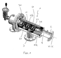
- numeral 10 generally designates a self-cleaning filter in accordance with an embodiment of the present invention.
- the self-cleaning filter comprises a liquid suction port 2, a liquid delivery port 3 and a tubular filter element 10, which is configured to filter the liquid that flows from the liquid suction port 2 to the liquid delivery port 3.
- the tubular filter element 10 extends in a longitudinal direction X-X.
- the tubular filter element 10 has a circular section with an axis A extending in the longitudinal direction X-X.
- the tubular filter element 10 has a filtering surface 10a, here defined by the inner surface, and an opposite surface 10b.
- the tubular filter element 10 is defined by a filter mesh.
- the self-cleaning filter 1 comprises a plurality of radially arranged suction nozzles 20 rotating relative to the tubular filter element 10 and spaced from each other in the longitudinal direction X-X.
- the suction nozzles 20 are arranged to rotate about an axis of rotation extending in the longitudinal direction X-X, and preferably coaxial with the axis A.
- suction nozzles 20 are arranged inside the tubular filter element 10.
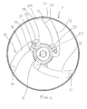
- the suction nozzles 20 are arranged in angularly spaced relationship. Particularly, two suction nozzles 20 arranged side by side in the longitudinal direction X-X are spaced at an angle of 120°.
- Each suction nozzle 20 comprises a suction pad 21 located in the proximity of the tubular filter element 10, particularly in the proximity of the inner surface 10a of the tubular filter element 10.
- the suction pad 21 has a suction port 22 for sucking the impurities filtered by the inner surface 10a of the tubular filter element 10.
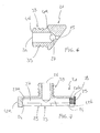
- the suction port 22 comprises a central portion 23 and two end portions 24 which are joined to the central portion 23 at opposite sides thereof to thereby form a slit, generally referenced 25 extending in the longitudinal direction X-X between the two end portions 24.
- the suction nozzles 20 are spaced in the longitudinal direction X-X such that, upon rotation of the nozzles 20 about the axis of rotation A, the inner surfaces of the tubular filter element 10 that have been swept by the slits 25 of two adjacent nozzles 20 overlap, and the ratio of the overlapping area to the slit area 25 ranges from 5% to 35%.
- the suction pad 21 further comprises a discharge opening 26, preferably disposed in line with the central portion 23.
- the suction pad 21 advantageously has a T-shape with a first rod portion 41 and a second head portion 42 arranged transverse to one end 41a of the first rod portion 41.
- the second portion 42 extends in the longitudinal direction X-X between two ends 42a, 42b and comprises the slit 25, whereas the first portion 41 extends in the direction Y-Y orthogonal to the longitudinal direction X-X from the end 41a to an end 41b, whereat it terminates with the discharge opening 26.
- the slit 25 tapers from each end portion 24 toward the central portion 23 in the longitudinal direction X-X.
- This configuration of the slit 25 affords a uniform suction pressure to be exerted along the entire longitudinal extent of the slit 25.
- the two end portions 24 and the central portion 23 have respective suction sections s1, s2.
- the suction section of the suction port 22 is at its maximum and equal to s1, at the two end portions 24 and at its minimum and equal to s2, at the central portion 23 and advantageously decreases uniformly from s2 to s1, from the end portions 24 toward the central portion 23 in the longitudinal direction X-X.
- the ratio of the suction section s2 of the central portion 23 to the suction section s1 of the two end portions 24 ranges from 0.5 to 0.8.
- the central portion is disposed in a middle position between the two end portions 24.
- the suction pad 21 comprises an expansion tank 27 disposed between the discharge opening 26 and the suction port 22 for connecting the suction port 22 with the discharge opening 26.
- the suction power may be increased, an additional volume being available between the suction port 22 and the discharge opening 26.
- the expansion tank 27 extends in the longitudinal direction X-X between two end portions 27a, 27b located at the ends 42a, 42b of the second portion 42 of the suction pad 21.
- the suction pad 21 has an opening 28 for access to the expansion tank 27. This access opening 28 is closed by a removable plug 29.
- the expansion tank 27 has a tubular shape, with an axis extending in the longitudinal direction X-X.
- the self-cleaning filter 1 further comprises a suction duct 30 disposed within the tubular filter element 10 and configured to rotate relative to the tubular filter element 10, in a direction of rotation (referenced R in the figures), about an axis X that extends in the longitudinal direction X-X.
- the suction duct 30 has an axis X coaxial with the axis A of the tubular filter element 10.
- the suction nozzles 20 are rotatably fixed to the suction duct 30, to rotate relative to the tubular filter element 10 along a circumferential direction in the direction of rotation R of the suction duct 30.
- the suction nozzles 20 radially project out of the suction duct 30.
- the suction duct 30 has a plurality of connecting apertures 31, each connecting aperture 31 being connected to a respective suction nozzle 20 through a respective connecting duct 32.
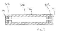
- Each connecting duct 32 extends between a first end 32a for connection to the suction nozzle 20 and a second end 32b for connection to the connecting aperture 31 and comprises a central portion 32c extending between the first end 32a and the second end 32b.
- each connecting duct 32 is at least partially made of an elastic material, preferably an elastomer, and is connected to the suction duct 30 such that the central portion 32c is able to elastically bend relative to the second end 32b at least circumferentially, either in the direction of rotation or in a direction opposite to the direction of rotation.
- the elasticity of the connecting duct 32 and the flexibility of the central portion 32c relative to the second end 32b allow the suction pad 21 to move relative to the suction duct 30 and relative to the tubular filter element 10 with many degrees of freedom, such that the suction pad can optimally adhere to the inner surface 10a of the tubular filter element 10 and that the force applied to the suction pad 21 does not damage the tubular filter element 10 and also reduces the wear caused by the wiping motion of the suction pad 21 on the inner surface 10a.
- the elasticity of the connecting duct 32 further allows the suction pad 21 to conform with the irregularities of the inner surface 10a of the tubular filter element 10, if the latter has a non-perfectly circular profile, and if very large particles are present.
- the central portion 32c elastically bends relative to the second end 32b, the first end 32a and the suction nozzle 20 connected thereto will elastically move at least circumferentially relative to the second end 32b.
- the suction duct 30 has a plurality of connecting sleeves 52.
- Each connecting sleeve 52 is rotatably fixed to the suction duct 30 and is connected at opposite sides to a respective connecting aperture 31 and a respective connecting duct 32.
- Each connecting sleeve 52 has a sleeve end 52a that is only partially inserted in its respective connecting duct 32 at the second end 32b of the connecting duct 32 and terminates at such second end 32b of the connecting duct 32.
- each connecting sleeve 52 has a sleeve axis B and the central portion 32c of each connecting duct 32 is able to elastically circumferentially bend relative to the sleeve axis B, either in the direction of rotation or in the direction opposite to the direction of rotation.
- the end 41b of the suction pad 21 is only partially inserted in its respective connecting duct 32 at the first end 32a of the connecting duct 32 and terminates at such first end 32a of the connecting duct 32.
- each connecting duct 32 is entirely made of an elastic material.
- a collar 50 mounted coaxial with the suction duct 30, is provided for easier connection and fixation of the connecting duct 32 with and to the suction duct 30.
- the collar 50 comprises a quick-connect mechanism 51 and the connecting sleeve 52 connects each connecting duct 32 with a respective connecting aperture 31.
- the collar 50 is an open ring having two ends designed to be moved toward each other, and the quick-connect mechanism 51 is identified by a fastening assembly composed of a screw 54 and a nut 55 located at the two ends 53 of the open ring, for tightening and loosening the collar 50 on the suction duct 30.
- the connecting sleeve 52 has a first end, corresponding to the above mentioned sleeve end 52a, for connection to the connecting duct 32 and a second end 52b for connection to the connecting aperture 31.
- rotationally restraining members 33 are provided to prevent rotation of each connecting duct 32 relative to its respective sleeve 52 and relative to its respective suction pad 21.
- the rotationally restraining members 33 comprise a plurality of teeth 34 formed at opposite ends of the connecting duct 32, and a plurality of grooves 35 formed in the suction pad 21 and a plurality of grooves 36 formed in the connecting sleeve 52.
- the grooves 35 and 36 are configured for connection with respective teeth 34 of the connecting duct 32.
- a pipe clamp (not shown) may be applied to the exterior of the connecting duct 32 at the connection with the connecting sleeve 52 and with the suction pad 21 for improved fixation effectiveness.
Landscapes
- Chemical & Material Sciences (AREA)
- Chemical Kinetics & Catalysis (AREA)
- Cleaning In General (AREA)
- Ultra Sonic Daignosis Equipment (AREA)
- Filtering Of Dispersed Particles In Gases (AREA)
Applications Claiming Priority (2)
| Application Number | Priority Date | Filing Date | Title |
|---|---|---|---|
| ITMI20141617 | 2014-09-19 | ||
| ITMI20141620 | 2014-09-19 |
Publications (2)
| Publication Number | Publication Date |
|---|---|
| EP3000517A1 true EP3000517A1 (fr) | 2016-03-30 |
| EP3000517B1 EP3000517B1 (fr) | 2018-01-03 |
Family
ID=54145703
Family Applications (1)
| Application Number | Title | Priority Date | Filing Date |
|---|---|---|---|
| EP15186083.0A Active EP3000517B1 (fr) | 2014-09-19 | 2015-09-21 | Filtre autonettoyant |
Country Status (2)
| Country | Link |
|---|---|
| EP (1) | EP3000517B1 (fr) |
| ES (1) | ES2662057T3 (fr) |
Cited By (6)
| Publication number | Priority date | Publication date | Assignee | Title |
|---|---|---|---|---|
| CN108126396A (zh) * | 2018-02-08 | 2018-06-08 | 江苏优耐特过滤装备有限公司 | 吸吮式自清洗过滤器 |
| CN108176112A (zh) * | 2016-06-16 | 2018-06-19 | 徐嘉 | 一种净水器 |
| IT201700076873A1 (it) * | 2017-07-07 | 2019-01-07 | Alfa Water S R L | Filtro autopulente |
| CN109621516A (zh) * | 2019-01-25 | 2019-04-16 | 太原科技大学 | 一种高水基反冲洗过滤器 |
| IT201800003030A1 (it) * | 2018-02-26 | 2019-08-26 | Serenambiente S R L | Filtro autopulente |
| WO2023119055A1 (fr) * | 2021-12-23 | 2023-06-29 | Netafim Ltd | Buse d'aspiration pour filtre à tamis |
Citations (8)
| Publication number | Priority date | Publication date | Assignee | Title |
|---|---|---|---|---|
| EP0164932A2 (fr) * | 1984-06-04 | 1985-12-18 | Filtration Limited | Filtre à fluide et sa buse d'aspiration |
| WO1990003833A1 (fr) * | 1988-10-11 | 1990-04-19 | Herrmann Karl Heinz | Appareil de filtrage continu a lavage a contre-courant |
| US5554284A (en) * | 1994-01-11 | 1996-09-10 | Filterwerk Mann & Hummel Gmbh | Backwashable filter for fluids |
| WO2006021510A1 (fr) | 2004-08-25 | 2006-03-02 | Valerio Vernocchi | Filtre autonettoyant avec toile filtrante protegee |
| US20090050582A1 (en) | 2007-08-23 | 2009-02-26 | Shmuel Gil | Self-Cleaning System For Filter |
| WO2011112151A1 (fr) | 2010-03-08 | 2011-09-15 | Aalborg Industries Water Treatment Pte. Ltd. | Module de filtration auto-nettoyant |
| US20140021125A1 (en) | 2012-07-18 | 2014-01-23 | Dan Lin | Self-cleaning suction filter |
| EP2767321A1 (fr) | 2013-02-13 | 2014-08-20 | F.M., S.r.L. Unipersonale | Filtre autonettoyant |
-
2015
- 2015-09-21 ES ES15186083.0T patent/ES2662057T3/es active Active
- 2015-09-21 EP EP15186083.0A patent/EP3000517B1/fr active Active
Patent Citations (8)
| Publication number | Priority date | Publication date | Assignee | Title |
|---|---|---|---|---|
| EP0164932A2 (fr) * | 1984-06-04 | 1985-12-18 | Filtration Limited | Filtre à fluide et sa buse d'aspiration |
| WO1990003833A1 (fr) * | 1988-10-11 | 1990-04-19 | Herrmann Karl Heinz | Appareil de filtrage continu a lavage a contre-courant |
| US5554284A (en) * | 1994-01-11 | 1996-09-10 | Filterwerk Mann & Hummel Gmbh | Backwashable filter for fluids |
| WO2006021510A1 (fr) | 2004-08-25 | 2006-03-02 | Valerio Vernocchi | Filtre autonettoyant avec toile filtrante protegee |
| US20090050582A1 (en) | 2007-08-23 | 2009-02-26 | Shmuel Gil | Self-Cleaning System For Filter |
| WO2011112151A1 (fr) | 2010-03-08 | 2011-09-15 | Aalborg Industries Water Treatment Pte. Ltd. | Module de filtration auto-nettoyant |
| US20140021125A1 (en) | 2012-07-18 | 2014-01-23 | Dan Lin | Self-cleaning suction filter |
| EP2767321A1 (fr) | 2013-02-13 | 2014-08-20 | F.M., S.r.L. Unipersonale | Filtre autonettoyant |
Cited By (8)
| Publication number | Priority date | Publication date | Assignee | Title |
|---|---|---|---|---|
| CN108176112A (zh) * | 2016-06-16 | 2018-06-19 | 徐嘉 | 一种净水器 |
| IT201700076873A1 (it) * | 2017-07-07 | 2019-01-07 | Alfa Water S R L | Filtro autopulente |
| EP3424578A1 (fr) * | 2017-07-07 | 2019-01-09 | Alfa Water S.r.l. | Filtre a auto-nettoyage |
| CN108126396A (zh) * | 2018-02-08 | 2018-06-08 | 江苏优耐特过滤装备有限公司 | 吸吮式自清洗过滤器 |
| IT201800003030A1 (it) * | 2018-02-26 | 2019-08-26 | Serenambiente S R L | Filtro autopulente |
| EP3530336A1 (fr) * | 2018-02-26 | 2019-08-28 | Serenambiente S.r.l. | Filtre autonettoyant |
| CN109621516A (zh) * | 2019-01-25 | 2019-04-16 | 太原科技大学 | 一种高水基反冲洗过滤器 |
| WO2023119055A1 (fr) * | 2021-12-23 | 2023-06-29 | Netafim Ltd | Buse d'aspiration pour filtre à tamis |
Also Published As
| Publication number | Publication date |
|---|---|
| EP3000517B1 (fr) | 2018-01-03 |
| ES2662057T3 (es) | 2018-04-05 |
Similar Documents
| Publication | Publication Date | Title |
|---|---|---|
| EP3000517B1 (fr) | Filtre autonettoyant | |
| US20160331199A1 (en) | Adapter assembly and suction nozzle | |
| EP2695676B1 (fr) | Dispositif de pulvérisation rotative | |
| DE112015001378T5 (de) | Ejektoranordnung und Vakuumpumpe | |
| US9827600B2 (en) | Movable rack assembly with corner spray nozzles | |
| US20130196585A1 (en) | Joint construction, ventilation arm and ventilation system | |
| CN103201005A (zh) | 用于清洗在盘式过滤器中的滤布的包括紧凑喷雾喷嘴的装置 | |
| TWI746843B (zh) | 用於澆水工具之可見且可拆卸的過濾器 | |
| EP3424578B1 (fr) | Filtre a auto-nettoyage | |
| EP1657976B1 (fr) | Dispositif de tuyau flexible tubulaire | |
| WO2014051952A1 (fr) | Collier réglable pour tuyaux flexibles sanitaires | |
| EP3283232B1 (fr) | Tube télescopique | |
| KR20160001022A (ko) | 하수배관 맞춤형 막힘 제거 장치 | |
| CN108603629A (zh) | 波纹管限制器 | |
| US20150219047A1 (en) | Filter cleaning assembly | |
| EP2614761A3 (fr) | Système d'étanchéité pour un tuyau d'aspiration d'aspirateur | |
| AT515865B1 (de) | Axiallüfter | |
| WO2006021510A1 (fr) | Filtre autonettoyant avec toile filtrante protegee | |
| EP3801824B1 (fr) | Unité de filtre à air remplaçable et agencement de filtre à air | |
| KR101894550B1 (ko) | 협소공간에 적용되는 클리닝 장치 | |
| DE102015118649A1 (de) | Vorrichtung zum Verbinden eines elektrischen Kupplungselementes | |
| WO2016108253A3 (fr) | Appareil de nettoyage pour le nettoyage de tamis de filtre | |
| TWM553381U (zh) | 家用器具、特別是吸塵器的轉動聯結用之軸承環,以及相應的家用器具、特別是吸塵器 | |
| DE102009047446A1 (de) | Pumpe | |
| WO2018127897A2 (fr) | Adaptateur de tube d'aspiration doté de joints permettant d'atteindre un rétrécissement |
Legal Events
| Date | Code | Title | Description |
|---|---|---|---|
| PUAI | Public reference made under article 153(3) epc to a published international application that has entered the european phase |
Free format text: ORIGINAL CODE: 0009012 |
|
| AK | Designated contracting states |
Kind code of ref document: A1 Designated state(s): AL AT BE BG CH CY CZ DE DK EE ES FI FR GB GR HR HU IE IS IT LI LT LU LV MC MK MT NL NO PL PT RO RS SE SI SK SM TR |
|
| AX | Request for extension of the european patent |
Extension state: BA ME |
|
| 17P | Request for examination filed |
Effective date: 20160929 |
|
| RBV | Designated contracting states (corrected) |
Designated state(s): AL AT BE BG CH CY CZ DE DK EE ES FI FR GB GR HR HU IE IS IT LI LT LU LV MC MK MT NL NO PL PT RO RS SE SI SK SM TR |
|
| STAA | Information on the status of an ep patent application or granted ep patent |
Free format text: STATUS: REQUEST FOR EXAMINATION WAS MADE |
|
| RIN1 | Information on inventor provided before grant (corrected) |
Inventor name: CENDRON, NICOLA |
|
| RIC1 | Information provided on ipc code assigned before grant |
Ipc: B01D 29/11 20060101AFI20170612BHEP Ipc: B01D 29/68 20060101ALN20170612BHEP Ipc: B01D 29/33 20060101ALI20170612BHEP Ipc: B01D 29/64 20060101ALN20170612BHEP |
|
| GRAP | Despatch of communication of intention to grant a patent |
Free format text: ORIGINAL CODE: EPIDOSNIGR1 |
|
| STAA | Information on the status of an ep patent application or granted ep patent |
Free format text: STATUS: GRANT OF PATENT IS INTENDED |
|
| RIC1 | Information provided on ipc code assigned before grant |
Ipc: B01D 29/68 20060101ALN20170705BHEP Ipc: B01D 29/11 20060101AFI20170705BHEP Ipc: B01D 29/64 20060101ALN20170705BHEP Ipc: B01D 29/33 20060101ALI20170705BHEP |
|
| INTG | Intention to grant announced |
Effective date: 20170726 |
|
| GRAS | Grant fee paid |
Free format text: ORIGINAL CODE: EPIDOSNIGR3 |
|
| GRAA | (expected) grant |
Free format text: ORIGINAL CODE: 0009210 |
|
| STAA | Information on the status of an ep patent application or granted ep patent |
Free format text: STATUS: THE PATENT HAS BEEN GRANTED |
|
| AK | Designated contracting states |
Kind code of ref document: B1 Designated state(s): AL AT BE BG CH CY CZ DE DK EE ES FI FR GB GR HR HU IE IS IT LI LT LU LV MC MK MT NL NO PL PT RO RS SE SI SK SM TR |
|
| REG | Reference to a national code |
Ref country code: GB Ref legal event code: FG4D |
|
| REG | Reference to a national code |
Ref country code: CH Ref legal event code: EP Ref country code: AT Ref legal event code: REF Ref document number: 959701 Country of ref document: AT Kind code of ref document: T Effective date: 20180115 |
|
| REG | Reference to a national code |
Ref country code: IE Ref legal event code: FG4D |
|
| REG | Reference to a national code |
Ref country code: DE Ref legal event code: R096 Ref document number: 602015007134 Country of ref document: DE |
|
| RAP2 | Party data changed (patent owner data changed or rights of a patent transferred) |
Owner name: SATI S.R.L. |
|
| REG | Reference to a national code |
Ref country code: ES Ref legal event code: FG2A Ref document number: 2662057 Country of ref document: ES Kind code of ref document: T3 Effective date: 20180405 |
|
| REG | Reference to a national code |
Ref country code: NL Ref legal event code: MP Effective date: 20180103 |
|
| REG | Reference to a national code |
Ref country code: LT Ref legal event code: MG4D |
|
| REG | Reference to a national code |
Ref country code: AT Ref legal event code: MK05 Ref document number: 959701 Country of ref document: AT Kind code of ref document: T Effective date: 20180103 |
|
| PG25 | Lapsed in a contracting state [announced via postgrant information from national office to epo] |
Ref country code: NL Free format text: LAPSE BECAUSE OF FAILURE TO SUBMIT A TRANSLATION OF THE DESCRIPTION OR TO PAY THE FEE WITHIN THE PRESCRIBED TIME-LIMIT Effective date: 20180103 |
|
| PG25 | Lapsed in a contracting state [announced via postgrant information from national office to epo] |
Ref country code: LT Free format text: LAPSE BECAUSE OF FAILURE TO SUBMIT A TRANSLATION OF THE DESCRIPTION OR TO PAY THE FEE WITHIN THE PRESCRIBED TIME-LIMIT Effective date: 20180103 Ref country code: CY Free format text: LAPSE BECAUSE OF FAILURE TO SUBMIT A TRANSLATION OF THE DESCRIPTION OR TO PAY THE FEE WITHIN THE PRESCRIBED TIME-LIMIT Effective date: 20180103 Ref country code: HR Free format text: LAPSE BECAUSE OF FAILURE TO SUBMIT A TRANSLATION OF THE DESCRIPTION OR TO PAY THE FEE WITHIN THE PRESCRIBED TIME-LIMIT Effective date: 20180103 Ref country code: NO Free format text: LAPSE BECAUSE OF FAILURE TO SUBMIT A TRANSLATION OF THE DESCRIPTION OR TO PAY THE FEE WITHIN THE PRESCRIBED TIME-LIMIT Effective date: 20180403 Ref country code: FI Free format text: LAPSE BECAUSE OF FAILURE TO SUBMIT A TRANSLATION OF THE DESCRIPTION OR TO PAY THE FEE WITHIN THE PRESCRIBED TIME-LIMIT Effective date: 20180103 |
|
| PG25 | Lapsed in a contracting state [announced via postgrant information from national office to epo] |
Ref country code: RS Free format text: LAPSE BECAUSE OF FAILURE TO SUBMIT A TRANSLATION OF THE DESCRIPTION OR TO PAY THE FEE WITHIN THE PRESCRIBED TIME-LIMIT Effective date: 20180103 Ref country code: LV Free format text: LAPSE BECAUSE OF FAILURE TO SUBMIT A TRANSLATION OF THE DESCRIPTION OR TO PAY THE FEE WITHIN THE PRESCRIBED TIME-LIMIT Effective date: 20180103 Ref country code: SE Free format text: LAPSE BECAUSE OF FAILURE TO SUBMIT A TRANSLATION OF THE DESCRIPTION OR TO PAY THE FEE WITHIN THE PRESCRIBED TIME-LIMIT Effective date: 20180103 Ref country code: PL Free format text: LAPSE BECAUSE OF FAILURE TO SUBMIT A TRANSLATION OF THE DESCRIPTION OR TO PAY THE FEE WITHIN THE PRESCRIBED TIME-LIMIT Effective date: 20180103 Ref country code: AT Free format text: LAPSE BECAUSE OF FAILURE TO SUBMIT A TRANSLATION OF THE DESCRIPTION OR TO PAY THE FEE WITHIN THE PRESCRIBED TIME-LIMIT Effective date: 20180103 Ref country code: BG Free format text: LAPSE BECAUSE OF FAILURE TO SUBMIT A TRANSLATION OF THE DESCRIPTION OR TO PAY THE FEE WITHIN THE PRESCRIBED TIME-LIMIT Effective date: 20180403 Ref country code: IS Free format text: LAPSE BECAUSE OF FAILURE TO SUBMIT A TRANSLATION OF THE DESCRIPTION OR TO PAY THE FEE WITHIN THE PRESCRIBED TIME-LIMIT Effective date: 20180503 Ref country code: GR Free format text: LAPSE BECAUSE OF FAILURE TO SUBMIT A TRANSLATION OF THE DESCRIPTION OR TO PAY THE FEE WITHIN THE PRESCRIBED TIME-LIMIT Effective date: 20180404 |
|
| REG | Reference to a national code |
Ref country code: DE Ref legal event code: R097 Ref document number: 602015007134 Country of ref document: DE |
|
| PG25 | Lapsed in a contracting state [announced via postgrant information from national office to epo] |
Ref country code: AL Free format text: LAPSE BECAUSE OF FAILURE TO SUBMIT A TRANSLATION OF THE DESCRIPTION OR TO PAY THE FEE WITHIN THE PRESCRIBED TIME-LIMIT Effective date: 20180103 Ref country code: RO Free format text: LAPSE BECAUSE OF FAILURE TO SUBMIT A TRANSLATION OF THE DESCRIPTION OR TO PAY THE FEE WITHIN THE PRESCRIBED TIME-LIMIT Effective date: 20180103 Ref country code: EE Free format text: LAPSE BECAUSE OF FAILURE TO SUBMIT A TRANSLATION OF THE DESCRIPTION OR TO PAY THE FEE WITHIN THE PRESCRIBED TIME-LIMIT Effective date: 20180103 |
|
| PLBE | No opposition filed within time limit |
Free format text: ORIGINAL CODE: 0009261 |
|
| STAA | Information on the status of an ep patent application or granted ep patent |
Free format text: STATUS: NO OPPOSITION FILED WITHIN TIME LIMIT |
|
| PG25 | Lapsed in a contracting state [announced via postgrant information from national office to epo] |
Ref country code: SK Free format text: LAPSE BECAUSE OF FAILURE TO SUBMIT A TRANSLATION OF THE DESCRIPTION OR TO PAY THE FEE WITHIN THE PRESCRIBED TIME-LIMIT Effective date: 20180103 Ref country code: DK Free format text: LAPSE BECAUSE OF FAILURE TO SUBMIT A TRANSLATION OF THE DESCRIPTION OR TO PAY THE FEE WITHIN THE PRESCRIBED TIME-LIMIT Effective date: 20180103 Ref country code: SM Free format text: LAPSE BECAUSE OF FAILURE TO SUBMIT A TRANSLATION OF THE DESCRIPTION OR TO PAY THE FEE WITHIN THE PRESCRIBED TIME-LIMIT Effective date: 20180103 Ref country code: CZ Free format text: LAPSE BECAUSE OF FAILURE TO SUBMIT A TRANSLATION OF THE DESCRIPTION OR TO PAY THE FEE WITHIN THE PRESCRIBED TIME-LIMIT Effective date: 20180103 |
|
| 26N | No opposition filed |
Effective date: 20181005 |
|
| PG25 | Lapsed in a contracting state [announced via postgrant information from national office to epo] |
Ref country code: SI Free format text: LAPSE BECAUSE OF FAILURE TO SUBMIT A TRANSLATION OF THE DESCRIPTION OR TO PAY THE FEE WITHIN THE PRESCRIBED TIME-LIMIT Effective date: 20180103 |
|
| REG | Reference to a national code |
Ref country code: DE Ref legal event code: R119 Ref document number: 602015007134 Country of ref document: DE |
|
| PG25 | Lapsed in a contracting state [announced via postgrant information from national office to epo] |
Ref country code: MC Free format text: LAPSE BECAUSE OF FAILURE TO SUBMIT A TRANSLATION OF THE DESCRIPTION OR TO PAY THE FEE WITHIN THE PRESCRIBED TIME-LIMIT Effective date: 20180103 |
|
| REG | Reference to a national code |
Ref country code: CH Ref legal event code: PL |
|
| REG | Reference to a national code |
Ref country code: BE Ref legal event code: MM Effective date: 20180930 |
|
| REG | Reference to a national code |
Ref country code: IE Ref legal event code: MM4A |
|
| PG25 | Lapsed in a contracting state [announced via postgrant information from national office to epo] |
Ref country code: LU Free format text: LAPSE BECAUSE OF NON-PAYMENT OF DUE FEES Effective date: 20180921 |
|
| PG25 | Lapsed in a contracting state [announced via postgrant information from national office to epo] |
Ref country code: IE Free format text: LAPSE BECAUSE OF NON-PAYMENT OF DUE FEES Effective date: 20180921 Ref country code: DE Free format text: LAPSE BECAUSE OF NON-PAYMENT OF DUE FEES Effective date: 20190402 |
|
| PG25 | Lapsed in a contracting state [announced via postgrant information from national office to epo] |
Ref country code: LI Free format text: LAPSE BECAUSE OF NON-PAYMENT OF DUE FEES Effective date: 20180930 Ref country code: FR Free format text: LAPSE BECAUSE OF NON-PAYMENT OF DUE FEES Effective date: 20180930 Ref country code: BE Free format text: LAPSE BECAUSE OF NON-PAYMENT OF DUE FEES Effective date: 20180930 Ref country code: CH Free format text: LAPSE BECAUSE OF NON-PAYMENT OF DUE FEES Effective date: 20180930 |
|
| PG25 | Lapsed in a contracting state [announced via postgrant information from national office to epo] |
Ref country code: MT Free format text: LAPSE BECAUSE OF NON-PAYMENT OF DUE FEES Effective date: 20180921 |
|
| PG25 | Lapsed in a contracting state [announced via postgrant information from national office to epo] |
Ref country code: TR Free format text: LAPSE BECAUSE OF FAILURE TO SUBMIT A TRANSLATION OF THE DESCRIPTION OR TO PAY THE FEE WITHIN THE PRESCRIBED TIME-LIMIT Effective date: 20180103 |
|
| PG25 | Lapsed in a contracting state [announced via postgrant information from national office to epo] |
Ref country code: PT Free format text: LAPSE BECAUSE OF FAILURE TO SUBMIT A TRANSLATION OF THE DESCRIPTION OR TO PAY THE FEE WITHIN THE PRESCRIBED TIME-LIMIT Effective date: 20180103 |
|
| PG25 | Lapsed in a contracting state [announced via postgrant information from national office to epo] |
Ref country code: HU Free format text: LAPSE BECAUSE OF FAILURE TO SUBMIT A TRANSLATION OF THE DESCRIPTION OR TO PAY THE FEE WITHIN THE PRESCRIBED TIME-LIMIT; INVALID AB INITIO Effective date: 20150921 Ref country code: MK Free format text: LAPSE BECAUSE OF NON-PAYMENT OF DUE FEES Effective date: 20180103 |
|
| GBPC | Gb: european patent ceased through non-payment of renewal fee |
Effective date: 20190921 |
|
| PG25 | Lapsed in a contracting state [announced via postgrant information from national office to epo] |
Ref country code: GB Free format text: LAPSE BECAUSE OF NON-PAYMENT OF DUE FEES Effective date: 20190921 |
|
| P01 | Opt-out of the competence of the unified patent court (upc) registered |
Effective date: 20230602 |
|
| P02 | Opt-out of the competence of the unified patent court (upc) changed |
Effective date: 20230821 |
|
| PGFP | Annual fee paid to national office [announced via postgrant information from national office to epo] |
Ref country code: IT Payment date: 20250919 Year of fee payment: 11 |
|
| PGFP | Annual fee paid to national office [announced via postgrant information from national office to epo] |
Ref country code: ES Payment date: 20251028 Year of fee payment: 11 |