EP3000551A1 - Machine à souder pour grillage - Google Patents
Machine à souder pour grillage Download PDFInfo
- Publication number
- EP3000551A1 EP3000551A1 EP15002318.2A EP15002318A EP3000551A1 EP 3000551 A1 EP3000551 A1 EP 3000551A1 EP 15002318 A EP15002318 A EP 15002318A EP 3000551 A1 EP3000551 A1 EP 3000551A1
- Authority
- EP
- European Patent Office
- Prior art keywords
- wires
- lever
- welding machine
- wire
- transverse
- Prior art date
- Legal status (The legal status is an assumption and is not a legal conclusion. Google has not performed a legal analysis and makes no representation as to the accuracy of the status listed.)
- Granted
Links
Images


Classifications
-
- B—PERFORMING OPERATIONS; TRANSPORTING
- B21—MECHANICAL METAL-WORKING WITHOUT ESSENTIALLY REMOVING MATERIAL; PUNCHING METAL
- B21F—WORKING OR PROCESSING OF METAL WIRE
- B21F27/00—Making wire network, i.e. wire nets
- B21F27/12—Making special types or portions of network by methods or means specially adapted therefor
-
- B—PERFORMING OPERATIONS; TRANSPORTING
- B23—MACHINE TOOLS; METAL-WORKING NOT OTHERWISE PROVIDED FOR
- B23K—SOLDERING OR UNSOLDERING; WELDING; CLADDING OR PLATING BY SOLDERING OR WELDING; CUTTING BY APPLYING HEAT LOCALLY, e.g. FLAME CUTTING; WORKING BY LASER BEAM
- B23K11/00—Resistance welding; Severing by resistance heating
- B23K11/36—Auxiliary equipment
-
- B—PERFORMING OPERATIONS; TRANSPORTING
- B21—MECHANICAL METAL-WORKING WITHOUT ESSENTIALLY REMOVING MATERIAL; PUNCHING METAL
- B21F—WORKING OR PROCESSING OF METAL WIRE
- B21F23/00—Feeding wire in wire-working machines or apparatus
- B21F23/005—Feeding discrete lengths of wire or rod
-
- B—PERFORMING OPERATIONS; TRANSPORTING
- B21—MECHANICAL METAL-WORKING WITHOUT ESSENTIALLY REMOVING MATERIAL; PUNCHING METAL
- B21F—WORKING OR PROCESSING OF METAL WIRE
- B21F27/00—Making wire network, i.e. wire nets
- B21F27/08—Making wire network, i.e. wire nets with additional connecting elements or material at crossings
- B21F27/10—Making wire network, i.e. wire nets with additional connecting elements or material at crossings with soldered or welded crossings
-
- B—PERFORMING OPERATIONS; TRANSPORTING
- B23—MACHINE TOOLS; METAL-WORKING NOT OTHERWISE PROVIDED FOR
- B23K—SOLDERING OR UNSOLDERING; WELDING; CLADDING OR PLATING BY SOLDERING OR WELDING; CUTTING BY APPLYING HEAT LOCALLY, e.g. FLAME CUTTING; WORKING BY LASER BEAM
- B23K11/00—Resistance welding; Severing by resistance heating
- B23K11/002—Resistance welding; Severing by resistance heating specially adapted for particular articles or work
- B23K11/008—Manufacturing of metallic grids or mats by spot welding
- B23K11/0086—Grids or mats used in concrete structures
Definitions
- the invention relates to a wire mesh welding machine with a device for feeding the transverse wires deposited in the vicinity of the welding position to a group of parallel longitudinal wires of the grid lying in the horizontal working plane.
- the machine welds the transverse and longitudinal wires at their points of contact in time with the cross wires being fed, and longitudinally shifts the family of longitudinal wires in that cycle in the production flow direction.
- the Querdrahtzu Swissvorraum has a plurality of parallel, spaced on a horizontal working beam mounted, along an approximately elliptical path movable wire gripping arms, by means of which the transverse wires individually sequentially from a position close to the welding position can be tapped off and laterally at always constant place for the purpose of subsequent welding can be stored.
- the working beam carrying the wire gripping arms is horizontally movable by means of an eccentric rotatable by a fixed shaft and a push rod via a hinged to a fixed point closed system hinged lever and acts on the lever a vertical movement device for fixing the elliptical path.
- the invention aims to couple the two movements directly and to avoid these disadvantages.
- This object is achieved according to the invention in a wire mesh welding machine of the type described above, that acts on one of the lever of the articulated lever system another push rod for the vertical movement, which is driven by a further eccentric of the same drive shaft, and that on the system of levers vertical, resiliently variable length spring element, eg in the form of a pneumatic cylinder, which presses the working beam downwards or upwards and thus allows an additional, slight vertical movement of the wire gripping arms bearing working beam, depending on the diameter of the transverse wires.
- the lengths and locations of the levers, the eccentric and the push rods can be adjusted to achieve the desired approximately elliptical trajectory of the transverse wires.
- the spring element engages articulated on an angle lever whose one, approximately horizontal arm with the working beam is fixed and its other, about vertical arm via a link at the upper or lower end of the spring element and at a fixed point facing away from the upper or lower hinge point the closed system of hinged levers;
- another link is pivotally connected to the angle lever and with the lever system off the fixed point closing lever, which forms a joint-connected parallelogram together with the links and the approximately vertical arm of the angle lever. This ensures that the spring element remains in the vertical position regardless of the movement of the lever.
- the wire gripping arms preferably have at their tip a V-groove for positioning the transverse wire.
- the longitudinal wires preferably form a counter-hold when tapping and transporting the transverse wire in the V-groove along half of the approximately elliptical path. Any means of another kind for holding the transverse wire during transport and at the welds are therefore not required.
- the cross wire feeder is designed so that it can be placed either above or below the working plane of the welding machine, no matter where the shot channel for the transverse wires is located.
- the transverse wires can be deposited by means of the wire gripping arms from above and in the other case from below onto the group of parallel longitudinal wires lying in the horizontal working plane.
- the devices provided according to the invention for feeding the transverse wires to the group of longitudinal wires of the grid lying in the horizontal working plane are each arranged mirror-symmetrically below and above the working plane.
- Fig. 1 a mesh welding machine with a device for feeding the transverse wires from above onto a share in a horizontal working plane lying parallel longitudinal wires in a side view in the direction of the transverse wires
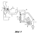
- Fig. 2 a grid welding machine with a device for feeding the transverse wires from below onto the family of longitudinal wires in the same view
- Fig. 3 a grid welding machine in the same view with two devices for feeding the transverse wires, one device feeding the transverse wires from above and the other device feeding the transverse wires from below onto the array of longitudinal wires.
- Fig. 1-3 are analog components designated by the same reference numerals.
- the reference numerals are partially omitted to avoid expansions.
- a transverse wire 1 is in a welding position on or under a family of parallel, arranged in a horizontal working plane 2 longitudinal wires extending side by side in the production flow direction 3 and in this direction 3 gradually in time with the feeding and subsequent welding of the transverse wires 1 are longitudinally displaced at the points of contact with the longitudinal wires.
- the longitudinal axes of the transverse wires 1 point in the page plane Fig. 1-3 into, so that they are shown only in their cross section. The longitudinal wires are not shown for clarity.
- the lower part indicated in the figures and the upper part of the welding machine indicated there are not essential to the invention and not designated.
- the cross wire feed device has a plurality of spaced parallel to a working beam 4 fixed wire grab arms 5, which tap the transverse wires 1 one by one from a designated 1 'position near the welding position of the respective cross wire 1 and laterally store it in the position of the subsequent welding.
- the transverse wires 1 are passed by means of a Einschman listening, which is not the subject of the invention and indicated at 6'.
- each cross wire 1 follows the in Fig. 1 lower (in Fig.
- the wire gripping arms 5 have at their tip a V-groove 5 'for positioning the transverse wire 1, wherein in the present embodiments, the longitudinal wires constitute the counter-stop during tapping and during transport of the transverse wire 1 along the half of the web 6.
- the wire gripping arms 5 carrying working beam 4 is by means of one of a fixedly mounted drive shaft 7 rotatable eccentric 8 and a push rod 9 via a hinged to a fixed point 10 closed system hinged together lever 11-14 horizontally.
- On a 12 of the lever 11-14 acts hinged thereto another push rod 16, which is driven by a further eccentric 15 of the same drive shaft 7 and provides for the vertical component of movement along the approximately elliptical path 6.
- the closed system hinged lever 11-14 for horizontal movement consists of three adjoining angle levers 11-13 and the lever system 11-14 closing lever 14, which is hinged to the middle angle lever 11 opposite ends of the two outer angle levers 12, 13 ,
- the push rod 16 is hinged to the angled position of a 12 formed as an angle lever lever 11-13.
- the work beam 4, to which a plurality of the parallel wire gripping arms 5 is fixed, is of a vertical, resiliently variable length spring element 17 in Fig. 1 down, in Fig. 2 can be pressed upwards, which a slight vertical movement of the working beam 4 and held at the top of the wire gripping arms 5 in the V-grooves 5 'transverse wire 1, depending on its diameter, allows.
- Fig. 3 pushes the respective spring element the upper working beam 4 down or the lower working beam 4 upwards.
- the spring element 17 is hinged to the system of levers 11-14 so that it remains in the vertical position regardless of the movement of the levers 11-14.
- the spring element 17 engages on a horizontal arm of an angle lever 18 articulated, which is fixed to the working beam 4.
- the other, approximately vertical arm of the angle lever 18 engages with its upper or lower end via a link 19 at the common pivot point, which articulated at the upper and lower end of the spring element 17 together with the upper or lower hinge point of the closed system of each other Lever 11-14 is formed, which hinge point is remote from the fixed point 10 and is formed between the levers 12 and 14.
- Another link 20 connects the lever 18 to the lever 14, which closes the lever system 11-14 away from the fixed point 10.
- the lever 14, together with the links 19, 20 and the approximately vertical arm of the angle lever 18 is a joint-linked parallelogram.
- variable-length spring element 17 is a pneumatic cylinder in the example shown, but can also be designed as a compression spring, which ensures the close contact between the respective transverse wires 1 and the longitudinal wires during welding, regardless of the wire diameters.
Landscapes
- Engineering & Computer Science (AREA)
- Mechanical Engineering (AREA)
- Manufacturing & Machinery (AREA)
- Wire Processing (AREA)
Applications Claiming Priority (1)
| Application Number | Priority Date | Filing Date | Title |
|---|---|---|---|
| ATA627/2014A AT515914B1 (de) | 2014-08-08 | 2014-08-08 | Drahtgitter-Schweißmaschine |
Publications (2)
| Publication Number | Publication Date |
|---|---|
| EP3000551A1 true EP3000551A1 (fr) | 2016-03-30 |
| EP3000551B1 EP3000551B1 (fr) | 2017-04-05 |
Family
ID=54035069
Family Applications (1)
| Application Number | Title | Priority Date | Filing Date |
|---|---|---|---|
| EP15002318.2A Not-in-force EP3000551B1 (fr) | 2014-08-08 | 2015-08-04 | Machine à souder pour grillage |
Country Status (2)
| Country | Link |
|---|---|
| EP (1) | EP3000551B1 (fr) |
| AT (1) | AT515914B1 (fr) |
Cited By (3)
| Publication number | Priority date | Publication date | Assignee | Title |
|---|---|---|---|---|
| CN109922916A (zh) * | 2016-12-14 | 2019-06-21 | Evg有限公司 | 格栅焊接机和用于制造金属线格栅的方法 |
| US10845778B2 (en) | 2017-03-30 | 2020-11-24 | Lincoln Global, Inc. | Workpiece positioner and welding sequencer |
| CN113770731A (zh) * | 2021-09-16 | 2021-12-10 | 建科机械(天津)股份有限公司 | 一种多面立体塔柱成型系统 |
Families Citing this family (1)
| Publication number | Priority date | Publication date | Assignee | Title |
|---|---|---|---|---|
| CN120791138B (zh) * | 2025-08-15 | 2026-02-17 | 东莞市千鸿精密制造有限公司 | 一种机械加工用机械臂自动焊接装备 |
Citations (4)
| Publication number | Priority date | Publication date | Assignee | Title |
|---|---|---|---|---|
| EP0241449A1 (fr) * | 1986-04-02 | 1987-10-14 | EVG Entwicklungs- u. Verwertungs- Gesellschaft m.b.H. | Machine à souder par résistance par points nombreuses |
| DE3635017C1 (de) * | 1986-10-15 | 1987-10-22 | Jaeger Emil Gmbh Co Kg | Querdrahtzufuehrung zu einer Gitterschweissmaschine |
| DE3741372C1 (de) * | 1987-12-07 | 1988-11-03 | Jaeger Emil Gmbh Co Kg | Querdrahtzufuehrung fuer eine Gitterschweissmaschine |
| DE10122398C1 (de) * | 2001-05-09 | 2002-10-02 | Jaeger Emil Gmbh Co Kg | Querdrahtzuführung für eine Gitterschweißmaschine, mit wählbarer Zangen-Bahnkurve, und Schweißmaschine mit einer derartigen Querdrahtzuführung |
Family Cites Families (1)
| Publication number | Priority date | Publication date | Assignee | Title |
|---|---|---|---|---|
| IT1315091B1 (it) * | 2000-05-11 | 2003-02-03 | Impianti Industriali Spa | Dispositivo caricatore di fili metallici e relativo procedimento |
-
2014
- 2014-08-08 AT ATA627/2014A patent/AT515914B1/de not_active IP Right Cessation
-
2015
- 2015-08-04 EP EP15002318.2A patent/EP3000551B1/fr not_active Not-in-force
Patent Citations (4)
| Publication number | Priority date | Publication date | Assignee | Title |
|---|---|---|---|---|
| EP0241449A1 (fr) * | 1986-04-02 | 1987-10-14 | EVG Entwicklungs- u. Verwertungs- Gesellschaft m.b.H. | Machine à souder par résistance par points nombreuses |
| DE3635017C1 (de) * | 1986-10-15 | 1987-10-22 | Jaeger Emil Gmbh Co Kg | Querdrahtzufuehrung zu einer Gitterschweissmaschine |
| DE3741372C1 (de) * | 1987-12-07 | 1988-11-03 | Jaeger Emil Gmbh Co Kg | Querdrahtzufuehrung fuer eine Gitterschweissmaschine |
| DE10122398C1 (de) * | 2001-05-09 | 2002-10-02 | Jaeger Emil Gmbh Co Kg | Querdrahtzuführung für eine Gitterschweißmaschine, mit wählbarer Zangen-Bahnkurve, und Schweißmaschine mit einer derartigen Querdrahtzuführung |
Cited By (3)
| Publication number | Priority date | Publication date | Assignee | Title |
|---|---|---|---|---|
| CN109922916A (zh) * | 2016-12-14 | 2019-06-21 | Evg有限公司 | 格栅焊接机和用于制造金属线格栅的方法 |
| US10845778B2 (en) | 2017-03-30 | 2020-11-24 | Lincoln Global, Inc. | Workpiece positioner and welding sequencer |
| CN113770731A (zh) * | 2021-09-16 | 2021-12-10 | 建科机械(天津)股份有限公司 | 一种多面立体塔柱成型系统 |
Also Published As
| Publication number | Publication date |
|---|---|
| AT515914A4 (de) | 2016-01-15 |
| AT515914B1 (de) | 2016-01-15 |
| EP3000551B1 (fr) | 2017-04-05 |
Similar Documents
| Publication | Publication Date | Title |
|---|---|---|
| EP3000551B1 (fr) | Machine à souder pour grillage | |
| DE19628556A1 (de) | Vorrichtung zur Entnahme und Zuführung von Formteilen | |
| DE2327168A1 (de) | Rohrentnahmevorrichtung | |
| DE102011014953B4 (de) | Biegevorrichtung für stab- und rohrförmige Werkstücke | |
| DE2741581C3 (de) | Vorrichtung zum Transport von Bolzen, Muttern o.dgl. Werkstücken auf Mehrstufenbearbeitungsmaschinen | |
| DE202004000213U1 (de) | Vorrichtung zum Zuführen eines bolzenförmigen Elements zu einer Verarbeitungseinheit | |
| AT516092A1 (de) | Vorrichtung und Verfahren zum Transport von schlauchförmigen Sackkörpern | |
| DE102006003522A1 (de) | Transfersystem mit Wendevorrichtung | |
| EP1422343B1 (fr) | Dispositif pour le montage d'attaches de rails | |
| DE3922532C1 (fr) | ||
| DE3040655A1 (de) | Be- und/oder entladegeraet fuer pressen, stanzen o.dgl. werkzeugmaschinen | |
| DE102005026150B3 (de) | Schwenkgreifer mit Spannbacken | |
| EP2394777A1 (fr) | Dispositif destiné à la séparation de pièces | |
| EP1767475B1 (fr) | Dispositif pour pousser des articles d'un convoyeur à bande à un autre | |
| DE2723080C2 (de) | Vorrichtung zum Abschieben und Vereinzeln von paarweise auf einem Zuführrollgang angeförderten Knüppelabschnitten | |
| DE3600082C2 (fr) | ||
| DE3923857A1 (de) | Vorrichtung zum abschneiden von runddraht oder dergleichen | |
| DE102015116225B4 (de) | Vorrichtung zur Bildung von Verpackungseinheiten | |
| DE307915C (fr) | ||
| EP0974412A2 (fr) | Dispositif d'alimentation pivotable pour le pivotement transversal de pièces allongées, en particulier piéces en fil métalliques | |
| DE202026101585U1 (de) | Vorrichtung zum Wenden von Behältern | |
| WO1997027979A1 (fr) | Dispositif permettant de travailler un brin de materiau plastique | |
| DD296051A5 (de) | Vorrichtung zur vereinzelung von auf einer schraegrutsche liegenden materialien | |
| DE544684C (de) | Vorrichtung zum Verhaengen des Geflechts an Rundflechtautomaten | |
| DE4304902A1 (de) | Vorschubeinrichtung zum schrittweisen Material- und/oder Werkstücktransport an bzw. in Produktionsmaschinen, wie Ziehpressen |
Legal Events
| Date | Code | Title | Description |
|---|---|---|---|
| PUAI | Public reference made under article 153(3) epc to a published international application that has entered the european phase |
Free format text: ORIGINAL CODE: 0009012 |
|
| 17P | Request for examination filed |
Effective date: 20150804 |
|
| AK | Designated contracting states |
Kind code of ref document: A1 Designated state(s): AL AT BE BG CH CY CZ DE DK EE ES FI FR GB GR HR HU IE IS IT LI LT LU LV MC MK MT NL NO PL PT RO RS SE SI SK SM TR |
|
| AX | Request for extension of the european patent |
Extension state: BA ME |
|
| GRAP | Despatch of communication of intention to grant a patent |
Free format text: ORIGINAL CODE: EPIDOSNIGR1 |
|
| INTG | Intention to grant announced |
Effective date: 20161116 |
|
| GRAS | Grant fee paid |
Free format text: ORIGINAL CODE: EPIDOSNIGR3 |
|
| GRAA | (expected) grant |
Free format text: ORIGINAL CODE: 0009210 |
|
| AK | Designated contracting states |
Kind code of ref document: B1 Designated state(s): AL AT BE BG CH CY CZ DE DK EE ES FI FR GB GR HR HU IE IS IT LI LT LU LV MC MK MT NL NO PL PT RO RS SE SI SK SM TR |
|
| REG | Reference to a national code |
Ref country code: GB Ref legal event code: FG4D Free format text: NOT ENGLISH |
|
| REG | Reference to a national code |
Ref country code: CH Ref legal event code: EP Ref country code: CH Ref legal event code: NV Representative=s name: ISLER AND PEDRAZZINI AG, CH |
|
| REG | Reference to a national code |
Ref country code: AT Ref legal event code: REF Ref document number: 881348 Country of ref document: AT Kind code of ref document: T Effective date: 20170415 |
|
| REG | Reference to a national code |
Ref country code: IE Ref legal event code: FG4D Free format text: LANGUAGE OF EP DOCUMENT: GERMAN |
|
| REG | Reference to a national code |
Ref country code: DE Ref legal event code: R096 Ref document number: 502015000788 Country of ref document: DE |
|
| REG | Reference to a national code |
Ref country code: NL Ref legal event code: MP Effective date: 20170405 |
|
| REG | Reference to a national code |
Ref country code: LT Ref legal event code: MG4D |
|
| PG25 | Lapsed in a contracting state [announced via postgrant information from national office to epo] |
Ref country code: NL Free format text: LAPSE BECAUSE OF FAILURE TO SUBMIT A TRANSLATION OF THE DESCRIPTION OR TO PAY THE FEE WITHIN THE PRESCRIBED TIME-LIMIT Effective date: 20170405 |
|
| PG25 | Lapsed in a contracting state [announced via postgrant information from national office to epo] |
Ref country code: FI Free format text: LAPSE BECAUSE OF FAILURE TO SUBMIT A TRANSLATION OF THE DESCRIPTION OR TO PAY THE FEE WITHIN THE PRESCRIBED TIME-LIMIT Effective date: 20170405 Ref country code: GR Free format text: LAPSE BECAUSE OF FAILURE TO SUBMIT A TRANSLATION OF THE DESCRIPTION OR TO PAY THE FEE WITHIN THE PRESCRIBED TIME-LIMIT Effective date: 20170706 Ref country code: LT Free format text: LAPSE BECAUSE OF FAILURE TO SUBMIT A TRANSLATION OF THE DESCRIPTION OR TO PAY THE FEE WITHIN THE PRESCRIBED TIME-LIMIT Effective date: 20170405 Ref country code: HR Free format text: LAPSE BECAUSE OF FAILURE TO SUBMIT A TRANSLATION OF THE DESCRIPTION OR TO PAY THE FEE WITHIN THE PRESCRIBED TIME-LIMIT Effective date: 20170405 Ref country code: NO Free format text: LAPSE BECAUSE OF FAILURE TO SUBMIT A TRANSLATION OF THE DESCRIPTION OR TO PAY THE FEE WITHIN THE PRESCRIBED TIME-LIMIT Effective date: 20170705 Ref country code: ES Free format text: LAPSE BECAUSE OF FAILURE TO SUBMIT A TRANSLATION OF THE DESCRIPTION OR TO PAY THE FEE WITHIN THE PRESCRIBED TIME-LIMIT Effective date: 20170405 |
|
| PG25 | Lapsed in a contracting state [announced via postgrant information from national office to epo] |
Ref country code: LV Free format text: LAPSE BECAUSE OF FAILURE TO SUBMIT A TRANSLATION OF THE DESCRIPTION OR TO PAY THE FEE WITHIN THE PRESCRIBED TIME-LIMIT Effective date: 20170405 Ref country code: PL Free format text: LAPSE BECAUSE OF FAILURE TO SUBMIT A TRANSLATION OF THE DESCRIPTION OR TO PAY THE FEE WITHIN THE PRESCRIBED TIME-LIMIT Effective date: 20170405 Ref country code: SE Free format text: LAPSE BECAUSE OF FAILURE TO SUBMIT A TRANSLATION OF THE DESCRIPTION OR TO PAY THE FEE WITHIN THE PRESCRIBED TIME-LIMIT Effective date: 20170405 Ref country code: BG Free format text: LAPSE BECAUSE OF FAILURE TO SUBMIT A TRANSLATION OF THE DESCRIPTION OR TO PAY THE FEE WITHIN THE PRESCRIBED TIME-LIMIT Effective date: 20170705 Ref country code: RS Free format text: LAPSE BECAUSE OF FAILURE TO SUBMIT A TRANSLATION OF THE DESCRIPTION OR TO PAY THE FEE WITHIN THE PRESCRIBED TIME-LIMIT Effective date: 20170405 Ref country code: IS Free format text: LAPSE BECAUSE OF FAILURE TO SUBMIT A TRANSLATION OF THE DESCRIPTION OR TO PAY THE FEE WITHIN THE PRESCRIBED TIME-LIMIT Effective date: 20170805 |
|
| REG | Reference to a national code |
Ref country code: DE Ref legal event code: R097 Ref document number: 502015000788 Country of ref document: DE |
|
| PG25 | Lapsed in a contracting state [announced via postgrant information from national office to epo] |
Ref country code: RO Free format text: LAPSE BECAUSE OF FAILURE TO SUBMIT A TRANSLATION OF THE DESCRIPTION OR TO PAY THE FEE WITHIN THE PRESCRIBED TIME-LIMIT Effective date: 20170405 Ref country code: DK Free format text: LAPSE BECAUSE OF FAILURE TO SUBMIT A TRANSLATION OF THE DESCRIPTION OR TO PAY THE FEE WITHIN THE PRESCRIBED TIME-LIMIT Effective date: 20170405 Ref country code: EE Free format text: LAPSE BECAUSE OF FAILURE TO SUBMIT A TRANSLATION OF THE DESCRIPTION OR TO PAY THE FEE WITHIN THE PRESCRIBED TIME-LIMIT Effective date: 20170405 Ref country code: SK Free format text: LAPSE BECAUSE OF FAILURE TO SUBMIT A TRANSLATION OF THE DESCRIPTION OR TO PAY THE FEE WITHIN THE PRESCRIBED TIME-LIMIT Effective date: 20170405 Ref country code: CZ Free format text: LAPSE BECAUSE OF FAILURE TO SUBMIT A TRANSLATION OF THE DESCRIPTION OR TO PAY THE FEE WITHIN THE PRESCRIBED TIME-LIMIT Effective date: 20170405 |
|
| PLBE | No opposition filed within time limit |
Free format text: ORIGINAL CODE: 0009261 |
|
| STAA | Information on the status of an ep patent application or granted ep patent |
Free format text: STATUS: NO OPPOSITION FILED WITHIN TIME LIMIT |
|
| PG25 | Lapsed in a contracting state [announced via postgrant information from national office to epo] |
Ref country code: SM Free format text: LAPSE BECAUSE OF FAILURE TO SUBMIT A TRANSLATION OF THE DESCRIPTION OR TO PAY THE FEE WITHIN THE PRESCRIBED TIME-LIMIT Effective date: 20170405 |
|
| 26N | No opposition filed |
Effective date: 20180108 |
|
| PG25 | Lapsed in a contracting state [announced via postgrant information from national office to epo] |
Ref country code: MC Free format text: LAPSE BECAUSE OF FAILURE TO SUBMIT A TRANSLATION OF THE DESCRIPTION OR TO PAY THE FEE WITHIN THE PRESCRIBED TIME-LIMIT Effective date: 20170405 |
|
| REG | Reference to a national code |
Ref country code: BE Ref legal event code: MM Effective date: 20170831 |
|
| REG | Reference to a national code |
Ref country code: FR Ref legal event code: ST Effective date: 20180430 |
|
| REG | Reference to a national code |
Ref country code: IE Ref legal event code: MM4A |
|
| PG25 | Lapsed in a contracting state [announced via postgrant information from national office to epo] |
Ref country code: SI Free format text: LAPSE BECAUSE OF FAILURE TO SUBMIT A TRANSLATION OF THE DESCRIPTION OR TO PAY THE FEE WITHIN THE PRESCRIBED TIME-LIMIT Effective date: 20170405 |
|
| PG25 | Lapsed in a contracting state [announced via postgrant information from national office to epo] |
Ref country code: LU Free format text: LAPSE BECAUSE OF NON-PAYMENT OF DUE FEES Effective date: 20170804 |
|
| PG25 | Lapsed in a contracting state [announced via postgrant information from national office to epo] |
Ref country code: IE Free format text: LAPSE BECAUSE OF NON-PAYMENT OF DUE FEES Effective date: 20170804 |
|
| PG25 | Lapsed in a contracting state [announced via postgrant information from national office to epo] |
Ref country code: FR Free format text: LAPSE BECAUSE OF NON-PAYMENT OF DUE FEES Effective date: 20170831 Ref country code: BE Free format text: LAPSE BECAUSE OF NON-PAYMENT OF DUE FEES Effective date: 20170831 |
|
| PG25 | Lapsed in a contracting state [announced via postgrant information from national office to epo] |
Ref country code: MT Free format text: LAPSE BECAUSE OF FAILURE TO SUBMIT A TRANSLATION OF THE DESCRIPTION OR TO PAY THE FEE WITHIN THE PRESCRIBED TIME-LIMIT Effective date: 20170405 |
|
| PG25 | Lapsed in a contracting state [announced via postgrant information from national office to epo] |
Ref country code: HU Free format text: LAPSE BECAUSE OF FAILURE TO SUBMIT A TRANSLATION OF THE DESCRIPTION OR TO PAY THE FEE WITHIN THE PRESCRIBED TIME-LIMIT; INVALID AB INITIO Effective date: 20150804 |
|
| PG25 | Lapsed in a contracting state [announced via postgrant information from national office to epo] |
Ref country code: CY Free format text: LAPSE BECAUSE OF FAILURE TO SUBMIT A TRANSLATION OF THE DESCRIPTION OR TO PAY THE FEE WITHIN THE PRESCRIBED TIME-LIMIT Effective date: 20170405 |
|
| PGFP | Annual fee paid to national office [announced via postgrant information from national office to epo] |
Ref country code: IT Payment date: 20190725 Year of fee payment: 5 Ref country code: DE Payment date: 20190802 Year of fee payment: 5 |
|
| PG25 | Lapsed in a contracting state [announced via postgrant information from national office to epo] |
Ref country code: MK Free format text: LAPSE BECAUSE OF FAILURE TO SUBMIT A TRANSLATION OF THE DESCRIPTION OR TO PAY THE FEE WITHIN THE PRESCRIBED TIME-LIMIT Effective date: 20170405 |
|
| PGFP | Annual fee paid to national office [announced via postgrant information from national office to epo] |
Ref country code: CH Payment date: 20190812 Year of fee payment: 5 |
|
| PG25 | Lapsed in a contracting state [announced via postgrant information from national office to epo] |
Ref country code: TR Free format text: LAPSE BECAUSE OF FAILURE TO SUBMIT A TRANSLATION OF THE DESCRIPTION OR TO PAY THE FEE WITHIN THE PRESCRIBED TIME-LIMIT Effective date: 20170405 |
|
| GBPC | Gb: european patent ceased through non-payment of renewal fee |
Effective date: 20190804 |
|
| PG25 | Lapsed in a contracting state [announced via postgrant information from national office to epo] |
Ref country code: PT Free format text: LAPSE BECAUSE OF FAILURE TO SUBMIT A TRANSLATION OF THE DESCRIPTION OR TO PAY THE FEE WITHIN THE PRESCRIBED TIME-LIMIT Effective date: 20170405 |
|
| PG25 | Lapsed in a contracting state [announced via postgrant information from national office to epo] |
Ref country code: AL Free format text: LAPSE BECAUSE OF FAILURE TO SUBMIT A TRANSLATION OF THE DESCRIPTION OR TO PAY THE FEE WITHIN THE PRESCRIBED TIME-LIMIT Effective date: 20170405 |
|
| PG25 | Lapsed in a contracting state [announced via postgrant information from national office to epo] |
Ref country code: GB Free format text: LAPSE BECAUSE OF NON-PAYMENT OF DUE FEES Effective date: 20190804 |
|
| REG | Reference to a national code |
Ref country code: DE Ref legal event code: R119 Ref document number: 502015000788 Country of ref document: DE |
|
| REG | Reference to a national code |
Ref country code: CH Ref legal event code: PL |
|
| PG25 | Lapsed in a contracting state [announced via postgrant information from national office to epo] |
Ref country code: CH Free format text: LAPSE BECAUSE OF NON-PAYMENT OF DUE FEES Effective date: 20200831 Ref country code: LI Free format text: LAPSE BECAUSE OF NON-PAYMENT OF DUE FEES Effective date: 20200831 |
|
| PG25 | Lapsed in a contracting state [announced via postgrant information from national office to epo] |
Ref country code: DE Free format text: LAPSE BECAUSE OF NON-PAYMENT OF DUE FEES Effective date: 20210302 Ref country code: IT Free format text: LAPSE BECAUSE OF NON-PAYMENT OF DUE FEES Effective date: 20200804 |
|
| REG | Reference to a national code |
Ref country code: AT Ref legal event code: MM01 Ref document number: 881348 Country of ref document: AT Kind code of ref document: T Effective date: 20200804 |
|
| PG25 | Lapsed in a contracting state [announced via postgrant information from national office to epo] |
Ref country code: AT Free format text: LAPSE BECAUSE OF NON-PAYMENT OF DUE FEES Effective date: 20200804 |