EP3000582B1 - Extruderschnecke - Google Patents
Extruderschnecke Download PDFInfo
- Publication number
- EP3000582B1 EP3000582B1 EP15185144.1A EP15185144A EP3000582B1 EP 3000582 B1 EP3000582 B1 EP 3000582B1 EP 15185144 A EP15185144 A EP 15185144A EP 3000582 B1 EP3000582 B1 EP 3000582B1
- Authority
- EP
- European Patent Office
- Prior art keywords
- screw
- extruder
- steps
- twin
- valleys
- Prior art date
- Legal status (The legal status is an assumption and is not a legal conclusion. Google has not performed a legal analysis and makes no representation as to the accuracy of the status listed.)
- Active
Links
Images
Classifications
-
- B—PERFORMING OPERATIONS; TRANSPORTING
- B29—WORKING OF PLASTICS; WORKING OF SUBSTANCES IN A PLASTIC STATE IN GENERAL
- B29B—PREPARATION OR PRETREATMENT OF THE MATERIAL TO BE SHAPED; MAKING GRANULES OR PREFORMS; RECOVERY OF PLASTICS OR OTHER CONSTITUENTS OF WASTE MATERIAL CONTAINING PLASTICS
- B29B7/00—Mixing; Kneading
- B29B7/30—Mixing; Kneading continuous, with mechanical mixing or kneading devices
- B29B7/34—Mixing; Kneading continuous, with mechanical mixing or kneading devices with movable mixing or kneading devices
- B29B7/38—Mixing; Kneading continuous, with mechanical mixing or kneading devices with movable mixing or kneading devices rotary
- B29B7/46—Mixing; Kneading continuous, with mechanical mixing or kneading devices with movable mixing or kneading devices rotary with more than one shaft
- B29B7/48—Mixing; Kneading continuous, with mechanical mixing or kneading devices with movable mixing or kneading devices rotary with more than one shaft with intermeshing devices, e.g. screws
- B29B7/488—Parts, e.g. casings, sealings; Accessories, e.g. flow controlling or throttling devices
- B29B7/489—Screws
-
- B—PERFORMING OPERATIONS; TRANSPORTING
- B29—WORKING OF PLASTICS; WORKING OF SUBSTANCES IN A PLASTIC STATE IN GENERAL
- B29B—PREPARATION OR PRETREATMENT OF THE MATERIAL TO BE SHAPED; MAKING GRANULES OR PREFORMS; RECOVERY OF PLASTICS OR OTHER CONSTITUENTS OF WASTE MATERIAL CONTAINING PLASTICS
- B29B7/00—Mixing; Kneading
- B29B7/30—Mixing; Kneading continuous, with mechanical mixing or kneading devices
- B29B7/34—Mixing; Kneading continuous, with mechanical mixing or kneading devices with movable mixing or kneading devices
- B29B7/38—Mixing; Kneading continuous, with mechanical mixing or kneading devices with movable mixing or kneading devices rotary
- B29B7/46—Mixing; Kneading continuous, with mechanical mixing or kneading devices with movable mixing or kneading devices rotary with more than one shaft
- B29B7/48—Mixing; Kneading continuous, with mechanical mixing or kneading devices with movable mixing or kneading devices rotary with more than one shaft with intermeshing devices, e.g. screws
-
- B—PERFORMING OPERATIONS; TRANSPORTING
- B29—WORKING OF PLASTICS; WORKING OF SUBSTANCES IN A PLASTIC STATE IN GENERAL
- B29C—SHAPING OR JOINING OF PLASTICS; SHAPING OF MATERIAL IN A PLASTIC STATE, NOT OTHERWISE PROVIDED FOR; AFTER-TREATMENT OF THE SHAPED PRODUCTS, e.g. REPAIRING
- B29C48/00—Extrusion moulding, i.e. expressing the moulding material through a die or nozzle which imparts the desired form; Apparatus therefor
- B29C48/25—Component parts, details or accessories; Auxiliary operations
- B29C48/36—Means for plasticising or homogenising the moulding material or forcing it through the nozzle or die
- B29C48/395—Means for plasticising or homogenising the moulding material or forcing it through the nozzle or die using screws surrounded by a cooperating barrel, e.g. single screw extruders
- B29C48/40—Means for plasticising or homogenising the moulding material or forcing it through the nozzle or die using screws surrounded by a cooperating barrel, e.g. single screw extruders using two or more parallel screws or at least two parallel non-intermeshing screws, e.g. twin screw extruders
-
- B—PERFORMING OPERATIONS; TRANSPORTING
- B29—WORKING OF PLASTICS; WORKING OF SUBSTANCES IN A PLASTIC STATE IN GENERAL
- B29C—SHAPING OR JOINING OF PLASTICS; SHAPING OF MATERIAL IN A PLASTIC STATE, NOT OTHERWISE PROVIDED FOR; AFTER-TREATMENT OF THE SHAPED PRODUCTS, e.g. REPAIRING
- B29C48/00—Extrusion moulding, i.e. expressing the moulding material through a die or nozzle which imparts the desired form; Apparatus therefor
- B29C48/25—Component parts, details or accessories; Auxiliary operations
- B29C48/36—Means for plasticising or homogenising the moulding material or forcing it through the nozzle or die
- B29C48/395—Means for plasticising or homogenising the moulding material or forcing it through the nozzle or die using screws surrounded by a cooperating barrel, e.g. single screw extruders
- B29C48/40—Means for plasticising or homogenising the moulding material or forcing it through the nozzle or die using screws surrounded by a cooperating barrel, e.g. single screw extruders using two or more parallel screws or at least two parallel non-intermeshing screws, e.g. twin screw extruders
- B29C48/402—Means for plasticising or homogenising the moulding material or forcing it through the nozzle or die using screws surrounded by a cooperating barrel, e.g. single screw extruders using two or more parallel screws or at least two parallel non-intermeshing screws, e.g. twin screw extruders the screws having intermeshing parts
-
- B—PERFORMING OPERATIONS; TRANSPORTING
- B29—WORKING OF PLASTICS; WORKING OF SUBSTANCES IN A PLASTIC STATE IN GENERAL
- B29C—SHAPING OR JOINING OF PLASTICS; SHAPING OF MATERIAL IN A PLASTIC STATE, NOT OTHERWISE PROVIDED FOR; AFTER-TREATMENT OF THE SHAPED PRODUCTS, e.g. REPAIRING
- B29C48/00—Extrusion moulding, i.e. expressing the moulding material through a die or nozzle which imparts the desired form; Apparatus therefor
- B29C48/25—Component parts, details or accessories; Auxiliary operations
- B29C48/36—Means for plasticising or homogenising the moulding material or forcing it through the nozzle or die
- B29C48/50—Details of extruders
- B29C48/505—Screws
- B29C48/59—Screws characterised by details of the thread, i.e. the shape of a single thread of the material-feeding screw
- B29C48/60—Thread tops
-
- B—PERFORMING OPERATIONS; TRANSPORTING
- B29—WORKING OF PLASTICS; WORKING OF SUBSTANCES IN A PLASTIC STATE IN GENERAL
- B29C—SHAPING OR JOINING OF PLASTICS; SHAPING OF MATERIAL IN A PLASTIC STATE, NOT OTHERWISE PROVIDED FOR; AFTER-TREATMENT OF THE SHAPED PRODUCTS, e.g. REPAIRING
- B29C48/00—Extrusion moulding, i.e. expressing the moulding material through a die or nozzle which imparts the desired form; Apparatus therefor
- B29C48/25—Component parts, details or accessories; Auxiliary operations
- B29C48/36—Means for plasticising or homogenising the moulding material or forcing it through the nozzle or die
- B29C48/50—Details of extruders
- B29C48/505—Screws
- B29C48/62—Screws characterised by the shape of the thread channel, e.g. U-shaped
Definitions
- the screws therefore have an inlet end and an outlet end with an elongated core with an outwardly projecting helical screw web, the webs (mountains) of the one screw engaging in the chambers / channels (valleys) between the webs of the other screw.
- a space is created between the first extruder screw and the second extruder screw.
- the step-like structure increases the number of gaps, which improves the plasticization of the material.
- the multiple gaps lead to more leakage current which improves the mixing efficiency.
- the number of steps of the staircase comprises two or three steps depending on the width of the screw flight.
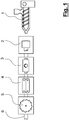
- Figure 1 shows a typical extrusion line as used today for profile extrusion, regardless of whether for the production of window profiles or tubes. It shows an extruder 1, in which plastic is melted and continuously fed into the extrusion die 2 for shaping. This is followed by a calibration and cooling station 3, depending on the profile, further cooling stations can be used. After the cooling stations, an extraction device 4 follows. In order to cut the endless profiles 6 to the desired length, a separating device 5 is then arranged.
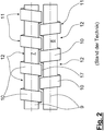
- FIG 2 shows a schematic representation of two intermeshing extruder screws in a section.
- a first extruder screw 7 and a second extruder screw 8 are arranged side by side in such a way that screw webs 10 engage as mountains 11 in the valleys 12 of the adjacent screw without the screws touching one another.
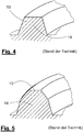
- the shape of the screw webs 10, which extend along the core 7 from an inlet end to an outlet end, can be trapezoidal in cross section, as in FIG Figure 5 or trapezoidal with bevel as in Figure 4 shown, executed.
- the execution according to the Figures 2 , 4 and 5 indicate the state of the art.
- the space 17 to the adjacent extruder screw is designated sf on the flanks and sw on the back.
- the space 17 can differ from step to step and from flank to flank and from flank to back.
- sfl can be different from sf2, different from sf3 and of course sw. but also sw1 different from sw2 and sw3.
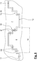
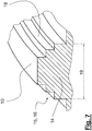
- the in Figure 7 reproduced screw flight 10 according to the invention shows the stair-shaped structure with the cross section 14, the stairs 15, the steps 18 and the width 19 of the screw flight 10.
- the screw flight 10 is indicated as a 3D representation.
Landscapes
- Engineering & Computer Science (AREA)
- Mechanical Engineering (AREA)
- Extrusion Moulding Of Plastics Or The Like (AREA)
Description
- Die Erfindung betrifft einen Doppelschneckenextruder für thermoplastische Materialien.
- Zum Aufschmelzen des Kunststoffgranulates wird dieses vor allem zwischen den Stegen der ineinander kämmenden Schnecken eines Doppelschneckenextruders gewalkt. Die Spalte, die durch den Schneckeneingriff gebildet sind, tragen wesentlich zur Scherung, Plastifizierung und Homogenisierung der Kunststoffmasse bei.
- Aus dem Stand der Technik ist die
DE 29 11 834 A1 bekannt, bei der das Prinzip des Kämmens von Doppelschnecken ersichtlich ist. Kämmende Doppelschnecken werden auch in den DruckschriftenDE 42 36 496 A1 ,DE 198 39 374 A1 ,US 2 745 643 A ,JP S61 175428 U CH 535 109 A US 1 423 768 A offenbart. Wesentlich ist dabei die Fläche die sich an den Stegen ergibt, um das Granulat zu walken. Im Zwickelbereich dringt ein Steg der Gegenschnecke in die Gänge der ersten ein und bildet an der engsten Stelle einen Walz- und Flankenspalt. Diese Spalte bzw. Zwischenräume und die Schneckenoberfläche beeinflussen die Plastifizierleistung der Schnecke. - Aufgabe der Erfindung ist es, eine bekannte Schneckengeometrie so weiterzubilden, dass eine größtmögliche Oberfläche an den Stegen und dadurch an der gesamten Oberfläche der Schnecke vorherrscht. Weiterhin soll der Verschleiß der Schnecke minimiert werden.
- Diese Aufgabe wird durch die Merkmale des Anspruchs 1 gelöst. Durch diese erfindungsgemäße Ausführung der Schneckenstege wird die Oberfläche der Extruderschnecke vergrößert.
- Die Schnecken weisen also ein Einlassende und ein Auslassende mit einem langgestreckten Kern mit einem nach außen abstehenden schraubenförmig verlaufenden Schneckensteg auf, wobei die Stege (Berge) der einen Schnecke in die Kammern/Kanal (Täler) zwischen den Stegen der anderen Schnecke eingreifen.
- Zwischen der ersten Extruderschnecke und der zweiten Extruderschnecke entsteht erfindungsgemäß ein Zwischenraum. Durch den treppenartigen Aufbau wird die Anzahl der Zwischenräume erhöht, wodurch die Plastifizierung des Materials verbessert wird. Die mehreren Lücken führen zu mehr Leckstrom was die Mischeffizienz verbessert.
- Vorteilhafterweise kann die Breite des Zwischenraums zwischen 0,5 mm und 3mm variieren und bei jeder Stufe unterschiedlich sein. Dies ermöglicht eine sehr variable Ausgestaltung des Stufenverlaufes der Treppen.
- Diese Flexibilität in der Ausführung führt erfindungsgemäß dazu, dass der Zwischenraum an den Flanken der Schneckenstege sich vom Zwischenraum am Rücken der Schneckenstege unterscheidet.
- In einer weiteren Fortbildung ist vorgesehen, dass die Anzahl der Stufen der Treppe in Abhängigkeit der Breite des Schneckensteges zwei oder drei Stufen umfasst.
- In den Zeichnungen wird schematisch eine erfindungsgemäße Vorrichtung gezeigt:
- Fig. 1
- zeigt eine typische Extrusionslinie
- Fig. 2
- zeigt einen Ausschnitt zweier kämmender Extruderschnecken
- Fig. 3
- zeigt einen Schnitt durch die Schnecken nach Figur 2
- Fig. 4
- einen 3D-Abschnitt eines Schneckensteges
- Fig. 5
- einen 3D-Abschnitt eines alternatives Schneckensteges
- Fig. 6
- zeigt einen Ausschnitt zweier kämmenden Extruderschnecken gemäß der Erfindung
- Fig. 7
- einen 3D-Abschnitt eines Schneckensteges gemäß der Erfindung
-
Figur 1 zeigt eine typische Extrusionslinie, wie sie heute für die Profilextrusion, egal, ob für die Produktion von Fensterprofilen oder Rohren, zum Einsatz kommt. Sie zeigt einen Extruder 1, in dem Kunststoff aufgeschmolzen wird, und kontinuierlich zur Formgebung ins Extrusionswerkzeug 2 gefördert wird. Daran schließt sich eine Kalibrier- und Kühlstation 3 an, je nach Profil können weitere Kühlstationen eingesetzt werden. Nach den Kühlstationen schließt sich eine Abzugsvorrichtung 4 an. Um die Endlosprofile 6 auf die gewünschte Länge abzuschneiden ist anschließend eine Trennvorrichtung 5 angeordnet. -
Figur 2 zeigt eine schematische Darstellung zweier kämmender Extuderschnecken in einem Ausschnitt. Eine erste Extruderschnecke 7 und eine zweite Extruderschnecke 8 sind so nebeneinander angeordnet, dass Schneckenstege 10 als Berge 11 in den Tälern 12 der benachbarten Schnecke eingreifen, ohne dass sich die Schnecken berühren. Zwischen beiden Schnecken besteht ein Zwischenraum 17. Die Form der Schneckenstege 10, die sich entlang des Kerns 7 von einem Einlassende zu einem Auslassende erstrecken, kann im Querschnitt trapezförmig, wie inFigur 5 oder trapezförmig mit Abschrägung wie inFigur 4 dargestellt, ausgeführt sein. Die Ausführung gemäß derFiguren 2 ,4 und 5 kennzeichnen den Stand der Technik. -
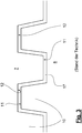
Figur 3 verdeutlicht dies noch einmal in einer vergrößerten Darstellung. Die erste Extruderschnecke 7 und die zweite Extruderschnecke 8 haben trapezförmige Schneckenstege 10 durch die Berge 11 und Täler 12 am Umfang der Schnecke entstehen. Die Extruderschnecken kämmen so nebeneinander, dass sie sich nicht berühren und ein Zwischenraum 17 vorherrscht. Auch dieFigur 3 gibt somit den Stand der Technik wieder. - Wie bereits oben erwähnt, sind in den
Figuren 4 und 5 beispielhaft zwei übliche Querschnitt der Schneckenstege 10 wieder gegeben. - Die
Figur 6 verdeutlicht in einem Ausschnitt, analog zurFigur 2 , den erfindungsgemäßen Aufbau der Schneckenstege 10. Sowohl die erste Extruderschnecke 7, als auch die zweite Extruderschnecke 8, hat einen Schneckensteg 10. Durch diesen Schneckensteg 10 entstehen am Umfang der Schnecke Berge 11 und Täler 12. - Die Flanken der Stege sind hier aber nun, im Gegensatz zum bekannten Stand der Technik, treppenartig ausgeführt. Der Stufenverlauf 16 der Treppen 15 der ersten Extruderschnecke 7 ist kongruent zum Stufenverlauf 16 der zweiten Extruderschnecke 8. Damit ist sichergestellt, dass immer die Erhebung, also der Berg 11, der einen Extruderschnecke, in die Vertiefung oder Aussparung, also dem Tal 12, der anderen Extruderschnecke passt, ohne dass diese sich berühren. Zwischen den beiden Schnecken besteht immer ein Zwischenraum 17. Je nach Breite 19 des Schneckensteges 10 weist die Treppe 15 zwei oder drei Stufen 18 auf.
- In
Figur 6 sind beispielhaft drei Stufen 18 je Treppe 15 dargestellt. Der Zwischenraum 17 zur benachbarten Extruderschnecke ist an den Flanken mit sf und an den Rücken mit sw bezeichnet. Der Zwischenraum 17 kann sich von Stufe zu Stufe und von Flanke zu Flanke sowie von Flanke zu Rücken unterscheiden. Somit kann sfl unterschiedlich zu sf2, unterschiedlich zu sf3 und natürlich auch zu sw sein. aber auch sw1 unterschiedlich zu sw2 und sw3. - Der in
Figur 7 wiedergegebene erfindungsgemäße Schneckensteg 10 zeigt den treppenförmigen Aufbau mit dem Querschnitt 14, der Treppe 15, den Stufen 18 und die Breite 19 des Schneckensteges 10. Zur Verdeutlichung ist der Schneckensteg 10 als 3D-Darstellung angedeutet. -
- 1
- Extruder
- 2
- Extrusionswerkzeug
- 3
- Kalibrier- und Kühltank
- 4
- Abzugsvorrichtung
- 5
- Trennvorrichtung
- 6
- Profil
- 7
- erste Extruderschnecke
- 8
- zweite Extruderschnecke
- 9
- Kern von 7 oder 8
- 10
- Schneckenstege von 7 oder 8
- 11
- Berge von 7 oder 8
- 12
- Täler von 7 oder 8
- 13
- Geometrie von 10
- 14
- Querschnitt von 10
- 15
- Treppe von 10
- 16
- Stufenverlauf von 15
- 17
- Zwischenraum zwischen 7 und 8
- 18
- Stufe von 15
- 19
- Breite von 10
- sw
- 17 am Rücken von 10
- sf
- 17 an der Flanke von 10
Claims (4)
- Doppelschneckenextruder für thermoplastische Materialien, mit einer ersten (7) und einer zweiten (8) Extruderschnecke,
wobei die Extruderschnecken (7, 8) jeweils ein Einlassende, ein Auslassende und einen Kern (9) aufweisen, wobei über den Kern (9) schraubenförmig verlaufende Schneckenstege (10) vom Einlassende zum Auslassende angeordnet sind, so dass am Umfang der Schnecken Berge (11) und Täler (12) entstehen,
wobei die Berge (11) der ersten Schnecke (7) in die Täler (12) der zweiten Schnecke (8) und umgekehrt eingreifen und die Schneckenstege (10) eine Geometrie (13) aufweisen die im Querschnitt (14) treppenförmig ausgestaltet ist,
wobei die Treppen (15) so ausgeführt sind, dass ein Stufenverlauf der Berge (11) der ersten Schnecke (7) zu einem Stufenverlauf der Täler (12) der zweiten Schnecke (8) kongruent ist und zwischen der ersten Schnecke (7) und der zweiten Schnecke (8) ein Zwischenraum (17) entsteht, dadurch gekennzeichnet, dass
der Zwischenraum (17) an den Flanken (sf) der Schneckenstege (10) sich vom Zwischenraum (17) am Rücken (sw) der Schneckenstege (10) unterscheidet. - Doppelschneckenextruder nach Anspruch 1, dadurch gekennzeichnet, dass die Breite der Zwischenräume (17) (17) zwischen 0,5 mm und 3mm variiert.
- Doppelschneckenextruder nach Anspruch 2, dadurch gekennzeichnet, dass der Zwischenraum (17) bei jeder Stufe unterschiedlich ausgebildet ist.
- Doppelschneckenextruder nach einem der vorigen Ansprüche, dadurch gekennzeichnet, dass die Anzahl der Stufen (18) der Treppe (15) in Abhängigkeit der Breite (19) des Schneckensteges (10) zwei oder drei Stufen (18) umfasst.
Applications Claiming Priority (1)
| Application Number | Priority Date | Filing Date | Title |
|---|---|---|---|
| DE102014219706.6A DE102014219706B3 (de) | 2014-09-29 | 2014-09-29 | Extruderschnecke |
Publications (3)
| Publication Number | Publication Date |
|---|---|
| EP3000582A2 EP3000582A2 (de) | 2016-03-30 |
| EP3000582A3 EP3000582A3 (de) | 2016-04-13 |
| EP3000582B1 true EP3000582B1 (de) | 2020-03-25 |
Family
ID=54147023
Family Applications (1)
| Application Number | Title | Priority Date | Filing Date |
|---|---|---|---|
| EP15185144.1A Active EP3000582B1 (de) | 2014-09-29 | 2015-09-14 | Extruderschnecke |
Country Status (3)
| Country | Link |
|---|---|
| US (1) | US9827692B2 (de) |
| EP (1) | EP3000582B1 (de) |
| DE (1) | DE102014219706B3 (de) |
Families Citing this family (2)
| Publication number | Priority date | Publication date | Assignee | Title |
|---|---|---|---|---|
| EP3243679B1 (de) * | 2016-05-11 | 2019-07-10 | Ningbo Geely Automobile Research & Development Co., Ltd. | Ladeluftverschluss |
| DE102020101387B4 (de) | 2020-01-21 | 2022-09-01 | BC Extrusion Holding GmbH | Verfahren und Vorrichtung zum Reduzieren von Schwankungen des Ausstoßes von Kunststoffmasse |
Family Cites Families (11)
| Publication number | Priority date | Publication date | Assignee | Title |
|---|---|---|---|---|
| US1423768A (en) * | 1921-04-25 | 1922-07-25 | William S Holdaway | Pump |
| US2434707A (en) * | 1943-10-09 | 1948-01-20 | Bakelite Corp | Continuous milling process and apparatus |
| US2674104A (en) * | 1950-03-11 | 1954-04-06 | Welding Engineers | Material-cooling system and process |
| US2745643A (en) * | 1952-05-05 | 1956-05-15 | Martin Scheerle | Kneading pump |
| CH535109A (de) * | 1970-05-08 | 1973-03-31 | Plast Elastverarbeitungsmasch | Extruderschnecke |
| US3900187A (en) * | 1973-10-29 | 1975-08-19 | Baker Perkins Inc | Continuous mixing and/or kneading machine with co-wiping single lead screws |
| JPS5829733B2 (ja) * | 1977-11-19 | 1983-06-24 | 積水化学工業株式会社 | 押出機 |
| AT384991B (de) * | 1978-04-03 | 1988-02-10 | Cincinnati Milacron Austria | Doppelschneckenextruder |
| JPS61175428U (de) * | 1985-04-22 | 1986-11-01 | ||
| DE4236496A1 (de) | 1992-10-29 | 1994-05-05 | Theysohn Friedrich Fa | Doppelschneckenextruder |
| DE19839374A1 (de) * | 1998-08-30 | 2000-03-02 | Kab Gmbh | Äquidistante Flankenspalte |
-
2014
- 2014-09-29 DE DE102014219706.6A patent/DE102014219706B3/de not_active Expired - Fee Related
-
2015
- 2015-09-14 EP EP15185144.1A patent/EP3000582B1/de active Active
- 2015-09-28 US US14/867,036 patent/US9827692B2/en active Active
Non-Patent Citations (1)
| Title |
|---|
| None * |
Also Published As
| Publication number | Publication date |
|---|---|
| EP3000582A2 (de) | 2016-03-30 |
| DE102014219706B3 (de) | 2016-03-31 |
| EP3000582A3 (de) | 2016-04-13 |
| US20160089814A1 (en) | 2016-03-31 |
| US9827692B2 (en) | 2017-11-28 |
Similar Documents
| Publication | Publication Date | Title |
|---|---|---|
| EP1533101B2 (de) | Planetwalzenextruder zum Mischen und Extrudieren von Kunststoffen | |
| EP2212090B1 (de) | Extruderschnecke für einen schneckenextruder | |
| DE1502335A1 (de) | Schneckenpresse mit veraenderlichem Stauabschnitt | |
| EP2000609A1 (de) | Bewehrungsstab | |
| EP2540410A1 (de) | Schraube und Verfahren zur Herstellung eines Schraubengewindes | |
| DE102019129717A1 (de) | Einschneckenextruder | |
| DE10114727B4 (de) | Schneckenelement für gleichsinnig drehende Mehrschneckenextruder | |
| EP2335898B1 (de) | Planetwalzenextruder | |
| EP2773499B1 (de) | Verfahren zur herstellung eines verstärkten kunststoffgegenstands | |
| EP1396331B1 (de) | Strangförmige Fahrzeugdichtung sowie Verfahren und Vorrichtung zu ihrer Herstellung | |
| EP2001650B1 (de) | Schneckenelement | |
| DE102012008169A1 (de) | Extruder mit Materialeintrag durch Gehäuse | |
| EP0458012B1 (de) | Kabelführungseinrichtung und Verfahren zur Herstellung | |
| EP2921279B1 (de) | Vorrichtung und Verfahren zur Homogenisierung von Kunststoffschmelzen | |
| EP3093119A1 (de) | Extruderschnecke und verfahren zu ihrer umrüstung | |
| DE102014219706B3 (de) | Extruderschnecke | |
| DE102012008023B4 (de) | Einschneckenextruder | |
| DE69206624T2 (de) | Rotor für eine schraubenrotormaschine. | |
| DE102008045728C5 (de) | Walzstange | |
| DE3533225C2 (de) | ||
| EP3253554B1 (de) | Stopfschnecke | |
| DE3134479A1 (de) | "vorrichtung zum kontinuierlichen aufschmelzen und mischen von kunststoffen" | |
| DE1909009B2 (de) | Mehrgaengige extruderschnecke | |
| DE102010048925B4 (de) | Extruder zur Verarbeitung von Kunststoffen | |
| EP3450132B1 (de) | Endform-vorrichtung zum ausformen von extrudierten kautschukmischungen zu einem gesamtkautschukelement, ein extruder-form-system umfassend die endform-vorrichtung, und verwendungen |
Legal Events
| Date | Code | Title | Description |
|---|---|---|---|
| PUAL | Search report despatched |
Free format text: ORIGINAL CODE: 0009013 |
|
| PUAI | Public reference made under article 153(3) epc to a published international application that has entered the european phase |
Free format text: ORIGINAL CODE: 0009012 |
|
| AK | Designated contracting states |
Kind code of ref document: A2 Designated state(s): AL AT BE BG CH CY CZ DE DK EE ES FI FR GB GR HR HU IE IS IT LI LT LU LV MC MK MT NL NO PL PT RO RS SE SI SK SM TR |
|
| AX | Request for extension of the european patent |
Extension state: BA ME |
|
| AK | Designated contracting states |
Kind code of ref document: A3 Designated state(s): AL AT BE BG CH CY CZ DE DK EE ES FI FR GB GR HR HU IE IS IT LI LT LU LV MC MK MT NL NO PL PT RO RS SE SI SK SM TR |
|
| AX | Request for extension of the european patent |
Extension state: BA ME |
|
| RIC1 | Information provided on ipc code assigned before grant |
Ipc: B29B 7/48 20060101ALN20160304BHEP Ipc: B29C 47/60 20060101AFI20160304BHEP Ipc: B29C 47/40 20060101ALI20160304BHEP |
|
| 17P | Request for examination filed |
Effective date: 20161013 |
|
| RBV | Designated contracting states (corrected) |
Designated state(s): AL AT BE BG CH CY CZ DE DK EE ES FI FR GB GR HR HU IE IS IT LI LT LU LV MC MK MT NL NO PL PT RO RS SE SI SK SM TR |
|
| STAA | Information on the status of an ep patent application or granted ep patent |
Free format text: STATUS: REQUEST FOR EXAMINATION WAS MADE |
|
| R17P | Request for examination filed (corrected) |
Effective date: 20161013 |
|
| REG | Reference to a national code |
Ref country code: DE Ref legal event code: R079 Ref document number: 502015012081 Country of ref document: DE Free format text: PREVIOUS MAIN CLASS: B29C0047600000 Ipc: B29C0048600000 |
|
| GRAP | Despatch of communication of intention to grant a patent |
Free format text: ORIGINAL CODE: EPIDOSNIGR1 |
|
| STAA | Information on the status of an ep patent application or granted ep patent |
Free format text: STATUS: GRANT OF PATENT IS INTENDED |
|
| RIC1 | Information provided on ipc code assigned before grant |
Ipc: B29C 48/60 20190101AFI20191024BHEP Ipc: B29C 48/62 20190101ALN20191024BHEP Ipc: B29B 7/48 20060101ALN20191024BHEP Ipc: B29C 48/40 20190101ALI20191024BHEP |
|
| RIC1 | Information provided on ipc code assigned before grant |
Ipc: B29C 48/40 20190101ALI20191106BHEP Ipc: B29C 48/62 20190101ALN20191106BHEP Ipc: B29B 7/48 20060101ALN20191106BHEP Ipc: B29C 48/60 20190101AFI20191106BHEP |
|
| INTG | Intention to grant announced |
Effective date: 20191121 |
|
| RIC1 | Information provided on ipc code assigned before grant |
Ipc: B29C 48/60 20190101AFI20191111BHEP Ipc: B29C 48/62 20190101ALN20191111BHEP Ipc: B29C 48/40 20190101ALI20191111BHEP Ipc: B29B 7/48 20060101ALN20191111BHEP |
|
| GRAS | Grant fee paid |
Free format text: ORIGINAL CODE: EPIDOSNIGR3 |
|
| GRAA | (expected) grant |
Free format text: ORIGINAL CODE: 0009210 |
|
| STAA | Information on the status of an ep patent application or granted ep patent |
Free format text: STATUS: THE PATENT HAS BEEN GRANTED |
|
| AK | Designated contracting states |
Kind code of ref document: B1 Designated state(s): AL AT BE BG CH CY CZ DE DK EE ES FI FR GB GR HR HU IE IS IT LI LT LU LV MC MK MT NL NO PL PT RO RS SE SI SK SM TR |
|
| REG | Reference to a national code |
Ref country code: GB Ref legal event code: FG4D Free format text: NOT ENGLISH |
|
| REG | Reference to a national code |
Ref country code: DE Ref legal event code: R096 Ref document number: 502015012081 Country of ref document: DE |
|
| REG | Reference to a national code |
Ref country code: AT Ref legal event code: REF Ref document number: 1248071 Country of ref document: AT Kind code of ref document: T Effective date: 20200415 Ref country code: IE Ref legal event code: FG4D Free format text: LANGUAGE OF EP DOCUMENT: GERMAN |
|
| PG25 | Lapsed in a contracting state [announced via postgrant information from national office to epo] |
Ref country code: RS Free format text: LAPSE BECAUSE OF FAILURE TO SUBMIT A TRANSLATION OF THE DESCRIPTION OR TO PAY THE FEE WITHIN THE PRESCRIBED TIME-LIMIT Effective date: 20200325 Ref country code: FI Free format text: LAPSE BECAUSE OF FAILURE TO SUBMIT A TRANSLATION OF THE DESCRIPTION OR TO PAY THE FEE WITHIN THE PRESCRIBED TIME-LIMIT Effective date: 20200325 Ref country code: NO Free format text: LAPSE BECAUSE OF FAILURE TO SUBMIT A TRANSLATION OF THE DESCRIPTION OR TO PAY THE FEE WITHIN THE PRESCRIBED TIME-LIMIT Effective date: 20200625 |
|
| PG25 | Lapsed in a contracting state [announced via postgrant information from national office to epo] |
Ref country code: LV Free format text: LAPSE BECAUSE OF FAILURE TO SUBMIT A TRANSLATION OF THE DESCRIPTION OR TO PAY THE FEE WITHIN THE PRESCRIBED TIME-LIMIT Effective date: 20200325 Ref country code: SE Free format text: LAPSE BECAUSE OF FAILURE TO SUBMIT A TRANSLATION OF THE DESCRIPTION OR TO PAY THE FEE WITHIN THE PRESCRIBED TIME-LIMIT Effective date: 20200325 Ref country code: BG Free format text: LAPSE BECAUSE OF FAILURE TO SUBMIT A TRANSLATION OF THE DESCRIPTION OR TO PAY THE FEE WITHIN THE PRESCRIBED TIME-LIMIT Effective date: 20200625 Ref country code: GR Free format text: LAPSE BECAUSE OF FAILURE TO SUBMIT A TRANSLATION OF THE DESCRIPTION OR TO PAY THE FEE WITHIN THE PRESCRIBED TIME-LIMIT Effective date: 20200626 Ref country code: HR Free format text: LAPSE BECAUSE OF FAILURE TO SUBMIT A TRANSLATION OF THE DESCRIPTION OR TO PAY THE FEE WITHIN THE PRESCRIBED TIME-LIMIT Effective date: 20200325 |
|
| REG | Reference to a national code |
Ref country code: NL Ref legal event code: MP Effective date: 20200325 |
|
| REG | Reference to a national code |
Ref country code: LT Ref legal event code: MG4D |
|
| PG25 | Lapsed in a contracting state [announced via postgrant information from national office to epo] |
Ref country code: NL Free format text: LAPSE BECAUSE OF FAILURE TO SUBMIT A TRANSLATION OF THE DESCRIPTION OR TO PAY THE FEE WITHIN THE PRESCRIBED TIME-LIMIT Effective date: 20200325 |
|
| PG25 | Lapsed in a contracting state [announced via postgrant information from national office to epo] |
Ref country code: EE Free format text: LAPSE BECAUSE OF FAILURE TO SUBMIT A TRANSLATION OF THE DESCRIPTION OR TO PAY THE FEE WITHIN THE PRESCRIBED TIME-LIMIT Effective date: 20200325 Ref country code: LT Free format text: LAPSE BECAUSE OF FAILURE TO SUBMIT A TRANSLATION OF THE DESCRIPTION OR TO PAY THE FEE WITHIN THE PRESCRIBED TIME-LIMIT Effective date: 20200325 Ref country code: SM Free format text: LAPSE BECAUSE OF FAILURE TO SUBMIT A TRANSLATION OF THE DESCRIPTION OR TO PAY THE FEE WITHIN THE PRESCRIBED TIME-LIMIT Effective date: 20200325 Ref country code: SK Free format text: LAPSE BECAUSE OF FAILURE TO SUBMIT A TRANSLATION OF THE DESCRIPTION OR TO PAY THE FEE WITHIN THE PRESCRIBED TIME-LIMIT Effective date: 20200325 Ref country code: IS Free format text: LAPSE BECAUSE OF FAILURE TO SUBMIT A TRANSLATION OF THE DESCRIPTION OR TO PAY THE FEE WITHIN THE PRESCRIBED TIME-LIMIT Effective date: 20200725 Ref country code: PT Free format text: LAPSE BECAUSE OF FAILURE TO SUBMIT A TRANSLATION OF THE DESCRIPTION OR TO PAY THE FEE WITHIN THE PRESCRIBED TIME-LIMIT Effective date: 20200818 Ref country code: CZ Free format text: LAPSE BECAUSE OF FAILURE TO SUBMIT A TRANSLATION OF THE DESCRIPTION OR TO PAY THE FEE WITHIN THE PRESCRIBED TIME-LIMIT Effective date: 20200325 Ref country code: RO Free format text: LAPSE BECAUSE OF FAILURE TO SUBMIT A TRANSLATION OF THE DESCRIPTION OR TO PAY THE FEE WITHIN THE PRESCRIBED TIME-LIMIT Effective date: 20200325 |
|
| REG | Reference to a national code |
Ref country code: DE Ref legal event code: R097 Ref document number: 502015012081 Country of ref document: DE |
|
| PG25 | Lapsed in a contracting state [announced via postgrant information from national office to epo] |
Ref country code: IT Free format text: LAPSE BECAUSE OF FAILURE TO SUBMIT A TRANSLATION OF THE DESCRIPTION OR TO PAY THE FEE WITHIN THE PRESCRIBED TIME-LIMIT Effective date: 20200325 Ref country code: DK Free format text: LAPSE BECAUSE OF FAILURE TO SUBMIT A TRANSLATION OF THE DESCRIPTION OR TO PAY THE FEE WITHIN THE PRESCRIBED TIME-LIMIT Effective date: 20200325 Ref country code: ES Free format text: LAPSE BECAUSE OF FAILURE TO SUBMIT A TRANSLATION OF THE DESCRIPTION OR TO PAY THE FEE WITHIN THE PRESCRIBED TIME-LIMIT Effective date: 20200325 |
|
| PLBE | No opposition filed within time limit |
Free format text: ORIGINAL CODE: 0009261 |
|
| STAA | Information on the status of an ep patent application or granted ep patent |
Free format text: STATUS: NO OPPOSITION FILED WITHIN TIME LIMIT |
|
| PG25 | Lapsed in a contracting state [announced via postgrant information from national office to epo] |
Ref country code: PL Free format text: LAPSE BECAUSE OF FAILURE TO SUBMIT A TRANSLATION OF THE DESCRIPTION OR TO PAY THE FEE WITHIN THE PRESCRIBED TIME-LIMIT Effective date: 20200325 |
|
| 26N | No opposition filed |
Effective date: 20210112 |
|
| PG25 | Lapsed in a contracting state [announced via postgrant information from national office to epo] |
Ref country code: MC Free format text: LAPSE BECAUSE OF FAILURE TO SUBMIT A TRANSLATION OF THE DESCRIPTION OR TO PAY THE FEE WITHIN THE PRESCRIBED TIME-LIMIT Effective date: 20200325 |
|
| REG | Reference to a national code |
Ref country code: CH Ref legal event code: PL |
|
| GBPC | Gb: european patent ceased through non-payment of renewal fee |
Effective date: 20200914 |
|
| PG25 | Lapsed in a contracting state [announced via postgrant information from national office to epo] |
Ref country code: SI Free format text: LAPSE BECAUSE OF FAILURE TO SUBMIT A TRANSLATION OF THE DESCRIPTION OR TO PAY THE FEE WITHIN THE PRESCRIBED TIME-LIMIT Effective date: 20200325 |
|
| REG | Reference to a national code |
Ref country code: BE Ref legal event code: MM Effective date: 20200930 |
|
| PG25 | Lapsed in a contracting state [announced via postgrant information from national office to epo] |
Ref country code: LU Free format text: LAPSE BECAUSE OF NON-PAYMENT OF DUE FEES Effective date: 20200914 |
|
| PG25 | Lapsed in a contracting state [announced via postgrant information from national office to epo] |
Ref country code: FR Free format text: LAPSE BECAUSE OF NON-PAYMENT OF DUE FEES Effective date: 20200930 |
|
| PG25 | Lapsed in a contracting state [announced via postgrant information from national office to epo] |
Ref country code: IE Free format text: LAPSE BECAUSE OF NON-PAYMENT OF DUE FEES Effective date: 20200914 Ref country code: GB Free format text: LAPSE BECAUSE OF NON-PAYMENT OF DUE FEES Effective date: 20200914 Ref country code: LI Free format text: LAPSE BECAUSE OF NON-PAYMENT OF DUE FEES Effective date: 20200930 Ref country code: BE Free format text: LAPSE BECAUSE OF NON-PAYMENT OF DUE FEES Effective date: 20200930 Ref country code: CH Free format text: LAPSE BECAUSE OF NON-PAYMENT OF DUE FEES Effective date: 20200930 |
|
| PG25 | Lapsed in a contracting state [announced via postgrant information from national office to epo] |
Ref country code: MT Free format text: LAPSE BECAUSE OF FAILURE TO SUBMIT A TRANSLATION OF THE DESCRIPTION OR TO PAY THE FEE WITHIN THE PRESCRIBED TIME-LIMIT Effective date: 20200325 Ref country code: CY Free format text: LAPSE BECAUSE OF FAILURE TO SUBMIT A TRANSLATION OF THE DESCRIPTION OR TO PAY THE FEE WITHIN THE PRESCRIBED TIME-LIMIT Effective date: 20200325 |
|
| PG25 | Lapsed in a contracting state [announced via postgrant information from national office to epo] |
Ref country code: MK Free format text: LAPSE BECAUSE OF FAILURE TO SUBMIT A TRANSLATION OF THE DESCRIPTION OR TO PAY THE FEE WITHIN THE PRESCRIBED TIME-LIMIT Effective date: 20200325 Ref country code: AL Free format text: LAPSE BECAUSE OF FAILURE TO SUBMIT A TRANSLATION OF THE DESCRIPTION OR TO PAY THE FEE WITHIN THE PRESCRIBED TIME-LIMIT Effective date: 20200325 |
|
| P01 | Opt-out of the competence of the unified patent court (upc) registered |
Effective date: 20230530 |
|
| PGFP | Annual fee paid to national office [announced via postgrant information from national office to epo] |
Ref country code: DE Payment date: 20250930 Year of fee payment: 11 |
|
| PGFP | Annual fee paid to national office [announced via postgrant information from national office to epo] |
Ref country code: TR Payment date: 20250909 Year of fee payment: 11 |
|
| PGFP | Annual fee paid to national office [announced via postgrant information from national office to epo] |
Ref country code: AT Payment date: 20250918 Year of fee payment: 11 |