EP3000630B1 - Système de support pour un attelage ou un porte-charge - Google Patents
Système de support pour un attelage ou un porte-charge Download PDFInfo
- Publication number
- EP3000630B1 EP3000630B1 EP15184411.5A EP15184411A EP3000630B1 EP 3000630 B1 EP3000630 B1 EP 3000630B1 EP 15184411 A EP15184411 A EP 15184411A EP 3000630 B1 EP3000630 B1 EP 3000630B1
- Authority
- EP
- European Patent Office
- Prior art keywords
- component
- wall section
- support
- support assembly
- profile
- Prior art date
- Legal status (The legal status is an assumption and is not a legal conclusion. Google has not performed a legal analysis and makes no representation as to the accuracy of the status listed.)
- Active
Links
Images


Classifications
-
- B—PERFORMING OPERATIONS; TRANSPORTING
- B60—VEHICLES IN GENERAL
- B60D—VEHICLE CONNECTIONS
- B60D1/00—Traction couplings; Hitches; Draw-gear; Towing devices
- B60D1/48—Traction couplings; Hitches; Draw-gear; Towing devices characterised by the mounting
- B60D1/52—Traction couplings; Hitches; Draw-gear; Towing devices characterised by the mounting removably mounted
-
- B—PERFORMING OPERATIONS; TRANSPORTING
- B60—VEHICLES IN GENERAL
- B60D—VEHICLE CONNECTIONS
- B60D1/00—Traction couplings; Hitches; Draw-gear; Towing devices
- B60D1/01—Traction couplings or hitches characterised by their type
- B60D1/06—Ball-and-socket hitches
-
- B—PERFORMING OPERATIONS; TRANSPORTING
- B60—VEHICLES IN GENERAL
- B60D—VEHICLE CONNECTIONS
- B60D1/00—Traction couplings; Hitches; Draw-gear; Towing devices
- B60D1/48—Traction couplings; Hitches; Draw-gear; Towing devices characterised by the mounting
- B60D1/485—Traction couplings; Hitches; Draw-gear; Towing devices characterised by the mounting mounted by means of transversal members attached to the frame of a vehicle
Definitions
- the invention relates to a carrier assembly for a trailer hitch or a load carrier, as components at least comprising a cross member for mounting to a rear of a body of a motor vehicle and at least one arranged on the cross member mount for a trailer hitch or for a coupling part of a load carrier, according to the preamble of the claim 1.
- Such a support arrangement is for example in DE 78 08 690 U or EP 2 803 510 A2 described.
- welded joints are known. Furthermore, from the unpublished DE 10 2013 008 328.1 a receiving sleeve of sheet metal previously known, which has a collar with which the receiving sleeve is supported on an upper wall portion of a cross member serving as a profile tube.
- this attachment is not sufficient in many cases. Welded joints are also burdensome to the materials, ie they lead to deformations, changes in the structure and the like other problems that affect the dimensional accuracy and the load capacity of the support assembly.
- the voltage behavior of the support structure that is as continuous as possible, undisturbed voltage curve, for example on the support profile, is made possible low.
- the carrier arrangement is outstandingly suitable for lightweight construction, in particular with the smallest possible material wall thicknesses.
- the wall thickness of, for example, carrier tubes can be significantly lower.
- the geometries and shapes are much simpler and easier to design, yet due to the invention cheap and firmly connect with each other.
- lighter components for example made by forming, can be used. Consequently, therefore, significantly greater degrees of freedom are possible, especially with the second component, in particular the holder for the trailer coupling or the load carrier.
- the invention enables the economical use of energy, in particular heat.
- the resistance welding connection is directly present, for example, between the carrier profile and the second component. But it is also possible that the resistance welded connection is made between other components, but still serves to connect the second component to the carrier profile. For example, it is possible for the resistance welding connection to be made between a third component, which will be explained later, and the second component in order to firmly connect it to the carrier profile.
- the carrier profile may be a profile tube with a closed cross-section.
- the carrier profile can also be open, for example, on one side, for example in cross-section U-shaped or L-shaped.
- the cross-sectional geometry is also versatile.
- the carrier profile has a round or rectangular cross-section.
- Another, for example polygonal cross-section may have the carrier profile.
- the first and second wall sections are connected to one another, for example, by a third wall section. But they can also be connected to each other by a fourth wall portion, so as to form, for example, a total closed in cross-section profile.
- the first wall section forms, for example, an upper wall section, the second wall section a lower wall section.
- the first wall section can also form a front in the direction of travel, the second wall section a rear in the direction of travel wall section.
- a plug-in direction or assembly direction of the second component with respect to the carrier profile runs horizontally, while in the former case, the plugging direction or mounting direction of the second component with respect to the carrier profile (relative to the mounting position in the motor vehicle) is vertical. Even oblique courses of the plug-in direction or mounting direction are readily possible.
- the carrier profile for example, form the cross member.
- the carrier profile may also form a longitudinal member which is to be connected, for example, with a longitudinal side of a body of the motor vehicle.
- the second component may likewise be a profile component or be a carrier profile.
- a profile component for example, in the manner according to the invention, two carrier profiles, for example segments of a cross member, a cross member and a side member or the like, can be connected to one another.
- the second component is preferably the holder for the load carrier or the trailer coupling, for example a coupling arm.
- the load carrier or the trailer coupling can be releasably fastened to the holder.
- a plug connection is provided.
- a plug-in direction or mounting direction for plugging or plugging in the load carrier or the trailer coupling to or into the holder can, for example, run vertically. But also a horizontal assembly, especially in the case of a load carrier, is appropriate.
- the holder is, for example, a sleeve or a receiving tube for a trailer coupling or a plug-in end of a load carrier. But it is also possible that the holder forms, for example, a pivot bearing and / or a sliding bearing for a coupling arm or a receptacle for a load carrier.
- the holder is preferably a sheet-metal component, for example a sleeve made of sheet metal.
- a form-fitting receptacle for positive locking and / or for positive retention of the trailer coupling or the load carrier is provided on the holder.
- the connection of the invention of the second component or the holder with the carrier profile ensures that the positive connection recording is not thermally or at best hardly loaded, which is the dimensional accuracy.
- An advantageous measure provides that the second component, in particular in the region of the welded connection, is non-positively and / or positively connected to the carrier profile.
- a non-positive connection is produced, for example, by one of the components, for example the carrier component or the second component or even both components, being or being thermally treated, for example heated or cooled, and then connected to the respective other component.
- the cooling process or heating process creates a tension that pulls the components towards each other.
- a third component which will be explained later, due to a thermal pretreatment, ensure that the carrier profile and the second component are under tension towards each other.
- the positive connection advantageously contributes to the fact that a section of the second component or of the carrier component is shaped in the direction of the respective other component, namely the carrier component or second component. This can be done for example by a fold. Furthermore, the already mentioned third component can ensure that the second component is formed into the carrier component or the carrier component to the second component.
- ring segments can be provided on one end side of the second component, which can be shaped more easily, for example, radially outward than a closed circumference.
- a preferred embodiment provides that the second component and / or the carrier profile of the type are formed, that the respective other component is embraced in the manner of a clip.
- a clip may be provided on the second component, a kind of mouth, in which an inner circumference of an opening engages the carrier profile.
- a support contour on the second component can be supported on the outside of a wall section of the carrier profile, while in the intermediate space a second portion supports an inner side of the wall portion of the carrier profile. Between these clip portions or clip-like portions, a portion of the wall portion of the carrier profile is received.
- the second component protrudes into the intermediate space between the first wall section and the second wall section.
- this measure can serve to deform the section of the second component which protrudes into the intermediate space so as to be supported on the inside of the second wall section from the interior or intermediate space.
- the second component ends in the space between the wall sections.
- the second component passes through the intermediate space and then, so to speak from the second, for example, lower or in the direction of travel rear wall section penetrates the first, for example upper or front in the direction of travel wall portion and connected thereto.
- the second component may be arranged, for example, on an edge side, for example on a longitudinal end of the carrier profile, and from there into the intermediate space.
- a variant can also provide that an opening is provided on the carrier profile, for example on a lower wall in the installation position or in the direction of travel, wherein the second component engages in the opening in the direction of the intermediate space between the first and the second wall section. It can also be provided two openings, namely on the first and on the second wall portion, so that the second component passes through the carrier profile through the two openings.
- the second component expediently has an abutment contour, for example a step or a shoulder, and lies with a portion of the abutment contour, for example a leg or a shoulder on one of the Interspace remote from the outside of the second wall portion. It is possible that then still a game between, for example, an inner circumference of the opening and the second component is provided. However, it is preferred if the contact contour rests with a second portion on an inner periphery of the aforementioned opening.
- a step contour is possible, such that, for example, the second component with a first contact contour on an outer side of the second wall portion, for example, at the bottom of the cross member of the support assembly, rests in the space between the two wall sections of Carrier profile protrudes and rests against the inside of the second wall portion with a further, second abutment contour.
- One or both of the abovementioned investment contours is ideally suited to the fact that the or a resistance welding connection is provided there.
- a third component is provided, which is designed for example in the manner of a rivet or an abutment member.
- the third component is arranged according to the invention on the first wall portion.
- the third component projects from the first wall section into the intermediate space to the second wall section.
- an opening is provided on the first wall portion, in which the third component is inserted.
- the second and the third component are in contact with each other, for example in touching contact. This contact may preferably serve to transfer energy for the production of the welded joint.
- the third component can serve, for example, to support the second component with respect to its direction of longitudinal extension on the carrier profile, ie to absorb, for example, tensile forces which load the second component away from the carrier profile.
- the third component can also, in particular in addition to the above measure or separately and exclusively, serve to support the second component transversely to the longitudinal direction of the support profile.
- the third component is also suitable for reshaping the second component, for example in order to reshape mold sections radially outwards such that the positive connection to the carrier profile is produced.
- the third component can also serve, for example, to transmit exclusively electrical energy or other energy for producing a resistance-welded connection.
- the invention provides that the welded connection or a welded connection, in particular the aforementioned resistance welding connection, is arranged or provided between the second and the third component.
- the third component is supported on the first wall section, for example on the basis of a collar, a flange or a support projection, and firmly connected to the second component, so that the second component is supported on the first wall section via the third component.
- the fixed connection is a welded connection, in particular the already mentioned resistance welding connection.
- annular flange or an annular edge may be provided on the inner circumference of one component or on the outer circumference of the other component, which is used up in the production of the resistance welding connection, so to speak. But even individual, for example, linear or punctiform, radially inwardly or radially outwardly projecting projections may be provided for the production of resistance welding connection between the two components.
- a particularly preferred embodiment provides that the third component biases the second component in the direction of the carrier profile. This is for example possible because the third component in the heated state with the second Component has been connected, so that the third component is shrunk by cooling in the range of normal during operation of the carrier assembly normal temperature and thus biases the second component in the direction of the carrier profile.
- the second and third components pass through opposite sides of the carrier profile, that is, the first and the second wall portion, and are interconnected in the space between the wall portions. If then one or both of the second and third components were first heated and then cooled again, a tensile stress develops between the two interconnected components, which leads to a clamping action on the carrier profile. The carrier profile is clamped, as it were sandwiched between the two second and third components.
- the third component may for example be a solid component or else a sleeve or another hollow body.
- a hollow body or a sleeve had a bottom.
- the deformation, in particular in the case of a hollow body with bottom is permitted on the third component projections, in particular in the form of anti-rotation contours.
- These projections can serve to selectively press the second component in recesses on the carrier profile.
- the recesses are configured, for example, radially outwardly in front of the circumferential contour of the opening already explained, for example, on the second wall section projecting recesses.
- the projections can serve as ignition aids or "welding means", that is, they serve to produce the or a resistance welding connection.
- the welded connection in particular resistance welding connection, expediently comprises at least one line-shaped or punctiform welded connection section or is formed thereby.
- relatively narrow or short welding connection sections are provided, which the thermal stress of the second component or the third component and the carrier profile by the weld holds low. Deformations or structural changes are thus largely avoidable.
- the resistance welding connection is also for example a wire element, in particular a wire element in ring form, a welding wire or the like, which is placed between the components to be connected, for example, the second and the third component or the second component and the support profile and melts upon entry of electrical welding energy.
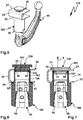
- a carrier assembly 10 includes, for example, a cross member 18, which is fastened on the rear 101 of a body 102 of a motor vehicle 100 by means of side supports 19.
- the cross member 18 extends transversely to a vehicle longitudinal direction 103 of the motor vehicle 100, that is to say in a transverse direction 104.
- the side members 19 extend approximately in the vehicle longitudinal direction 103.
- the carrier assembly 10 serves, for example, to carry a hitch 80.
- the carrier assembly 10 could also be referred to together with the below-explained coupling arm 81 as a total trailer coupling.
- the coupling arm 81 can be fastened, for example detachably, to a holder 50 of the carrier arrangement 10.
- the carrier assembly 10 is also alternatively suitable for fastening, for example, a schematically indicated load carrier 95 which can be connected to the cross member 18 on the basis of one or two coupling arms 96 or coupling carrier.
- a schematically indicated load carrier 95 which can be connected to the cross member 18 on the basis of one or two coupling arms 96 or coupling carrier.
- 96 brackets in the manner of the holder 50 may be provided for only schematically indicated coupling arms.
- the cross member 18 comprises a carrier profile 20, 120, each having an upper and a lower wall portion 21, 22.
- the upper wall section 21 forms in the words of the claims a first wall section, while the lower wall section 22 represents a second wall section.
- this is only due to the installation position of the carrier profile 20, that is to say that, for another orientation of the holder 50 with respect to the walls of the carrier profile 20, for example, the rear connecting wall section 23 in the direction of travel, which connects the wall sections 21, 22 with each other, may constitute a so-called second wall section.
- the carrier profile 20 with respect to the direction of travel or vehicle longitudinal direction 103 installed in reverse than in the carrier assembly 10 so that there is the connecting wall portion 23 in the direction of travel forward.
- the carrier profile 20 is for example U-shaped in cross-section, so open on one side.
- the carrier profile 120 is rectangular in cross section and closed. Namely, the carrier profile 120 has a further connecting wall section 24 which connects the wall sections 21, 22 to one another.
- the connecting wall sections 23, 24, for example, pass over curvature sections 26 into the wall sections 21, 22.
- other profile shapes readily come into question for the carrier profile, so not only the carrier profile 20 or 120, for example, so polygonal or round carrier profiles.
- Even round or rounded support profiles have namely upper and lower wall portions, even if they are possibly curved or arcuate.
- the wall sections 21, 22 serve for the direct support of the holder 50, which is directly supported on at least one of the wall sections 21, 22.
- the connecting wall sections 23 and / or 24 also fulfill a supporting function, namely by supporting the wall sections 21, 22 and thus stabilizing the carrier profile 20, 220. Indirectly or indirectly, therefore, the holder 50, even if it is directly supported only on the upper wall section 22, also supports itself on the lower wall section 22 via the connecting wall sections 23, 24.
- the holder 50 is for example tubular.
- the holder 50 has, for example, a plug-in receptacle 52 into which a plug-in end 84 of the coupling arm 81 can be inserted.
- the coupling arm 81 carries at its free end 82 a coupling piece 83, for example a coupling ball, for coupling a trailer or a load carrier, which can be placed on a known hitch, for example, on the coupling piece 83 can be attached.
- a coupling piece 83 for example a coupling ball
- a load carrier for example, a trailer or a load carrier
- an arm portion 85 Between the free end 82 and the plug end 84 extends an arm portion 85, which may have different courses depending on geometric relationships of the motor vehicle 100 and a bumper, not shown, in the embodiment with a few curves, otherwise substantially rectilinear.
- a relatively sharp curvature is provided, for example, directly next to the plug-in end 84, in particular because an insertion direction 93 in the exemplary embodiment is oriented substantially vertically.
- the geometry of the coupling arm 81 does not play a significant role here.
- the plug-in receptacle 52 there is also a receiving body 54 with a form-fitting receptacle or more form-fitting receptacles 55, which belong to a locking device 94, with the coupling arm 81 or the hitch 80 is adjustable to the holder 50, preferably also braced.
- the holder 50 is provided with form-locking receptacles 55 in which form-fit bodies configured as anti-rotation 91 engage in a form-fitting manner at the foot region of the plug end 84.
- the locking device 94 further comprises a displacement body 87 which is movably received in a channel 86 which extends in the plug end 84.
- the displacer 87 may form fit body 88, for example, balls, pins or the like, move radially outward from the male end 84, so that they engage positively in the form-locking receptacle 55, for example, an annular groove and preferably still clamp the form-fitting body or anti-rotation 91 in the form-fitting receptacles 55 (in the insertion direction 93).
- the form-fitting body 88 are movably mounted in radially extending channels 92 of the plug end 84.
- the displacer 87 can be moved in a conventional manner, for example, be adjusted linearly parallel to the direction of insertion 93. It can be seen that it is ensured by complex measures that the hitch 80, thus therefore the coupling arm 81, is locked and clamped with great strength and reliability with the holder 50. From this it is also clear that the carrier assembly 10, 110, 210 has to withstand large forces, in particular when driving the motor vehicle 100, which despite the lightweight construction explained below can easily be realized.
- the holder 50 is still formed as a semifinished product or a cast body, but could also readily consist of sheet metal, as described in the above-mentioned patent application. Especially this lightweight construction is particularly favorable for the fastening technique according to the invention, as will become clear below.
- the holder 50 forms a second component 60, which is firmly connected to the carrier profile 20.
- the component 60 has a projection 62 projecting in front of an end face 61, which passes through an opening 27 on the second wall section 22.
- the projection 62 protrudes into the gap 25 where it is connected to a third component 30.
- the third component 30 is designed, for example, in the manner of a rivet or an abutment body and penetrates an opening 28 on the upper, first wall section 21.
- the third component 30 has, for example, a main body 31 whose lower region in the drawing Connecting region 32 forms.
- the connection region 32 serves to establish a connection to the second component 60 in the intermediate space 25.
- the component 30 has a head 33 which could be supported on the upper side 29 of the wall section 21 facing away from the intermediate space 25, which, for example, in the variant of the third component 30 in FIG FIG. 4 the case is.
- the head 33 is provided at a distance 35 to the upper side 29 so that it does not support the second component with respect to a mounting axis 17, along which the components 30, 60 are inserted into the openings 28, 27.
- the mounting axis 17 is a vertical axis or an axis along which the second component 60 is subjected to tension with respect to the carrier profile 20.
- horizontally extending longitudinal direction of the holder 50, the mounting axis 17 or the tensile load on the axial direction would be correspondingly horizontal.
- the third component 30 with its outer circumference 39 on the inner circumference of the opening 28 in a form-fitting manner, so that the component 30 transverse to the mounting axis 17, for example along axial directions 16, 15, in FIG. 14 are shown, supporting acts.
- the axial directions 15, 16 extend, for example, parallel to the vehicle transverse direction 104 and the vehicle longitudinal direction 103, that is, for example, in the direction of a Y-axis and an X-axis, while the mounting axis or mounting axis 17 corresponds to a Z-axis (based on the specific installation situation the carrier assembly 210 with respect to the motor vehicle 100, which may be different in other motor vehicles and correspondingly differently adapted carrier arrangements according to the invention).
- the situation is, for example, such that it rests on the upper side 29 with a support surface 34 of a flange or collar 36, that is, it also supports the second component 60 with respect to the assembly axis 17.
- the second component 60 is supported with the end face 61 on the side facing away from the gap 25 side of the second wall portion 22 (in the drawing below).
- An outer circumference 64 of the projection 62 is located on the inner circumference of the opening 27 expediently form-fitting, so that here also a support transverse to the mounting axis 17, for example with respect to the axial directions 15, 16 is given.
- an insertion opening 63 At the free end region of the projection 62 is an insertion opening 63, in which the connecting portion 32 engages.
- a step 37 is provided on the outer circumference of the connecting region 32, so that an annular edge 38 is formed between the main body 31 and the connecting region 32.
- the connecting region 32 is designed so that when it engages in the insertion opening 63, its edge region or collar 65 is deformed radially outward (recognizable, for example, in FIG FIG. 3 ), so that the collar 65 so to speak surrounds the inner edge region of the opening 27 and thus the second wall section 22 like a clamp.
- a resistance welded connection 66 is still provided in the embodiment, which is caused by a melting of the annular edge 38. Namely, when the second component 30 is acted upon by electrical welding energy (represented by an arrow E), the annular edge 38, ie a projection, melts off and ensures that a welded connection between the second component 30 and the third component 60 is produced ,
- An optional or alternative measure is when, for example, another resistance welded connection 67 is made between the end face 61 and the free outside of the wall portion 22.
- a kind of annular projection is also provided on the end face 61, which melts with a corresponding input of energy. It would be possible but also a wire which is inserted into the space between the end face 61 and the wall portion 22 and melts with a corresponding input of energy and thus produces a welded joint between the end face 61 and the wall portion 22.
- third component 130 is configured in contrast to the third component 30 as a hollow body.
- a base body 131 has a sleeve-like basic structure and may optionally have a bottom.
- a peripheral wall of the main body 131 defines an interior 139. The peripheral wall is expediently in a form-fitting manner on the inner circumference of the opening 28.
- a collar 136 protrudes radially outward and serves for support on the upper or first wall section 21.
- oblique surfaces 137 are provided, for example a cone, which facilitate the insertion into the insertion opening 63.
- the oblique surfaces 137 also serve to widen the collar 65 on the projection 62 so that it engages around the inner circumference of the opening 28 in a form-fitting manner and / or in the manner of a clamp.
- a resistance welded connection 166 on the connection region 32 is formed, for example, by providing a circumferential or protruding circumferential projection radially outward of the connection region 32, ie in the contact region with the collar 65 so to speak, melts or ignites when the resistance welding is performed and thus causes a weld with the inner circumference of the collar 65.
- a further resistance welding connection 167 is provided, which is achieved, for example, by projecting an annular or hump-like projection 169 in front of the front side surface 61, which melts off by introducing electrical welding energy (corresponding to the arrow E) onto or into the third component 130 and creates the resistance welded joint 167.
- the holder 50 is formed by a second component 160, which abuts with its end face 161 on the outside (side facing away from the gap 25) of the carrier profile 90 or is supported there.
- a resistance welded connection 167 is expediently provided, but not absolutely necessary (this also applies to the resistance welded connection 67 in the aforementioned embodiments).
- a projection 162 is not only just in front of the inside of the wall portion 22, so only slightly into the gap 25 into it, but extends to the gap 25 facing inside of the first wall portion 21.
- the third component 330 is similar to the other third components 30, 130 inserted through the opening 28 and communicates with its connection portion 332 to an insertion 163 of the second component 160 before.
- inclined surfaces 337 can, as in FIG. 7 shown, a wall portion 168 of the projection 162 are displaced radially outward, so that it is supported, for example, on the inside of the first wall portion 21 facing the gap 25. That can but does not have to be.
- a welded connection in the form of a resistance welded connection 66 is provided between the third component 230 and the second component 160.
- the third component 330 does not have to be supported on the outside of the first wall section 21 facing away from the intermediate space 25, which is shown in FIGS. 5 and 6 is shown.
- the third component 330 is, as it were, completely inserted into the insertion opening 63, at least so far that its collar 365 is supported on the free outer side of the wall section 21.
- the conical inclined surfaces 337 ensure that the free end of the projection 62 is displaced outward, so that it rests positively against the inner side of the wall section 21 facing the intermediate space 25.
- a particularly preferred variant of the invention provides that, for example, the third components 130, 330 are first heated before they are inserted into the respective second components 60, 160. Then, when the third components 130, 330 cool again, this provides for a tensile stress in the direction of an arrow S in FIG. 7 ie that the third components 130, 330, so to speak, clamp the second components 60, 160 in the direction of the carrier profile 20. As a result, a traction is achieved.
- the positive connection is optional in this variant, but appropriate.
- the projection 362 penetrates even the upper opening in the drawing, namely the opening 28 of the first wall portion 21 and protrudes in front of the wall portion 21 and the opening 28.
- the third component 330 can then, when inserted into the insertion opening 63, displace the section of the projection 62 projecting from the top or free side 29 of the first wall section 21 radially outwards, so that it engages with a support section 70 on the upper side or outer side Side 29 of the wall portion 21 is supported.
- the support portion 70 includes a leg 71 which abuts the inner periphery of the opening 28 and a leg 72 which rests on the free side or upper side 29.
- the projection 262 penetrating the opening 27 and projecting into the gap 25 is in positive engagement with the second wall portion 22.
- a support portion 270 of the projection 262 has a leg 271 which on the inner circumference of the opening 27th is present or is supported there.
- Another leg 272 is, so to speak, on the inside of the wall portion 22, at least the wall surface in the intermediate space 25, preferably flat and positive.
- the third component 30 could serve directly for producing the support section 270. However, this would possibly not be suitable for forming the relatively far over the opening 27 cantilevered legs 272 or to form them so. Appropriately, therefore, a separate operation is provided, which is signaled by an arrow 1, wherein in this operation, a forming tool WZ produces the positive supporting contours of the support portion 270. In a second operation, indicated by an arrow 2, the third component 30 is mounted and the resistance welded connection 66 is produced.
- the second component 60 ie the holder 50
- the third component 230 has, for example, a main body 231 on which a head 233 is provided.
- the head 233 serves to support on the support section 20, for example, the upper wall portion 21. There he can with his bottom, namely a support surface 234, supported.
- the head 233 comprises, for example, a collar 236, which protrudes radially outward in front of the main body 231.
- the main body 231 is produced, for example, as a deep-drawn part, by cold extrusion or the like.
- the third component 230 is thus preferably a forming part, whereby a casting or forging, turning and / or milling part would be readily possible.
- a peripheral wall 240 defines an interior space 239. Furthermore, the interior space 239 is delimited by a bottom wall 235.
- This construction also has the advantage that projections 238, for example lugs, bumps or the like, can easily be produced at a connection region 232, namely a lower, bevelled region, which further widen the collar 65 of the second component 60 radially outward as the adjacent portions of the connecting portion 232, whereby an anti-rotation is provided.
- the projections 238 can also advantageously be used to form local resistance welded joints.
- the protrusions 238 can also serve, for example, the second component 260 described below, in the opening 227 of the carrier profile 220 in a manner secured against rotation FIG. 12 to maintain and / or facilitate the production of local resistance welding joints.
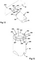
- a plurality of recesses 286 are provided as Verwood Anlagenskonturen.
- the anti-rotation contours 186 project radially outward in front of an inner circumference 287 of the opening 227.
- a flattening on the inner circumference of an opening in any case a polygonal or non-round or non-circular contour, is also suitable for securing a respective second or third component to a carrier profile in a manner secured against rotation.
- a plurality of recesses 266 are provided, so that the projection 262 is divided into ring segments 265.
- the ring segments 265 can be displaced more easily radially outwards by a third component, for example the third component 30, but also the third component 230, in order to achieve positive engagement with the second wall section 22.
- the respective third component 30, 230 is inserted, for example, in an insertion opening 263, wherein the ring segments 265 are deformed radially outward.
- the abovementioned projections 238 serve alternatively or additionally but also projections 267, which are formed, for example, during the production of the recesses 266.
- the projections 267 for example in the form of small lugs, protrude radially outwardly in front of the projection 262 and are thus arranged above the end face 261.
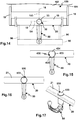
- a respective head of a third component can be optimally adapted to how the load distribution on the carrier profile is desired.
- the head 33 is selected so narrow that it essentially only loads the upper side 29 of the carrier profile 20.
- a flattening 434 is provided. Accordingly, the head 233 with its front portion 435 loads the rear in the direction of travel wall, namely the connecting wall portion 23, while the front in the direction of travel connecting wall portion 24 is not or less loaded due to the flattening 234. It is also possible that at the front in the direction of travel, for example, a U-shaped carrier profile no connection section is present. In this case, the flattening 434 is particularly favorable.
- a head 533 of a third component 530 has a relatively large extent, ie it preferably protrudes up to the connecting wall sections 23, 24, so that these can additionally bear the load by the holder 50 and not the entire load directly on the upper wall or the wall portion 21 acts.
Landscapes
- Engineering & Computer Science (AREA)
- Transportation (AREA)
- Mechanical Engineering (AREA)
- Connection Of Plates (AREA)
- Body Structure For Vehicles (AREA)
Claims (14)
- Système de support pour un attelage (80) ou un porte-charge, comprenant comme composants au moins une traverse (18) pour le montage sur un hayon d'une carrosserie d'un véhicule automobile (100) ainsi qu'au moins un support (50) agencé au niveau de la traverse (18) pour un attelage (80) ou pour une partie d'attelage d'un porte-charge, dans lequel le système de support (10) présente au moins deux composants raccordés par une liaison soudée, dans lequel le système de support (10) présente au moins un profil de support (20), en particulier un tube profilé, avec une première section de paroi (21) et avec une seconde section de paroi (22) à une distance de la première section de paroi (21) de sorte qu'un espace intermédiaire (25) entre la première section de paroi (21) et la seconde section de paroi (22) soit présent, et dans lequel au profil de support (20) un deuxième composant (60), en particulier le support (50), est fixé, dans lequel la liaison soudée est une liaison soudée à résistance (66, 67) et sert à la liaison du deuxième composant (60) avec le profil de support (20), dans lequel un troisième composant (30) est agencé au niveau de la première section de paroi (21) et dépasse de la première section de paroi (21) dans l'espace intermédiaire (25) vers la seconde section de paroi (22), et dans lequel le deuxième et le troisième composant (30) sont en contact l'un avec l'autre dans l'espace intermédiaire (22), caractérisé en ce que le troisième composant (30) s'appuie contre la première section de paroi au moyen d'un collet (36), d'une bride ou d'une saillie d'appui et est fixement raccordé au deuxième composant (60) au moyen d'une liaison soudée de sorte que le deuxième composant (60) s'appuie par le biais du troisième composant (30) contre la première section de paroi (21).
- Système de support selon la revendication 1, caractérisé en ce que le deuxième composant (60) est raccordé à force et/ou à complémentarité de formes au profil de support (20), en particulier dans la zone de la liaison soudée.
- Système de support selon la revendication 1 ou 2, caractérisé en ce que, pour l'établissement de la liaison à complémentarité de formes entre le deuxième composant (60) et le profil de support (20), une section du deuxième composant (60) ou du profil de support (20) est transformée en direction de l'autre composant respectif ou, pour la liaison à force entre le deuxième composant (60) et le profil de support (20), le profil de support (20) et/ou le deuxième composant (60) ou un troisième composant (30) maintenant le composant respectif a été raccordé à l'autre composant respectif en étant chauffé ou refroidi.
- Système de support selon l'une quelconque des revendications précédentes, caractérisé en ce que le deuxième composant (60) et/ou le profil de support (20) est déformé de telle manière que l'autre composant respectif soit entouré comme une agrafe.
- Système de support selon l'une quelconque des revendications précédentes, caractérisé en ce que le deuxième composant dépasse dans l'espace intermédiaire (25) entre la première section de paroi (21) et la seconde section de paroi (22) ou traverse l'espace intermédiaire (25) entre la première et la seconde section de paroi (22).
- Système de support selon l'une quelconque des revendications précédentes, caractérisé en ce qu'au niveau du profil de support (20), en particulier la seconde section de paroi (22), une ouverture (27) est prévue, avec laquelle le deuxième composant (60) vient en prise en direction de l'espace intermédiaire (25) entre la première section de paroi (21) et la deuxième section de paroi (22).
- Système de support selon l'une quelconque des revendications précédentes, caractérisé en ce que le deuxième composant (60) présente un contour d'appui, en particulier un étage, et repose avec une première section du contour d'appui contre un côté extérieur opposé à l'espace intermédiaire (25) de la seconde section de paroi (22) et avantageusement avec une seconde section du contour d'appui contre une périphérie intérieure de l'ouverture (27).
- Système de support selon l'une quelconque des revendications précédentes, caractérisé en ce que le deuxième composant (60) est agencé au niveau de la première section de paroi (21) et le troisième composant (30) configuré en particulier comme un composant de contre-palier, au niveau de la première section de paroi (21), dans lequel le deuxième et le troisième composant (30) sont en contact l'un avec l'autre, en particulier dans une liaison fixe, dans l'espace intermédiaire (25) entre les sections de paroi (22).
- Système de support selon la revendication 8, caractérisé en ce que le troisième composant (30) est prévu pour la transmission d'énergie pour l'établissement de la liaison soudée et/ou pour la transformation du deuxième composant (60) au sens d'un appui à complémentarité de formes contre le profil de support (20).
- Système de support selon la revendication 8 ou 9, caractérisé en ce que la liaison soudée ou une liaison soudée est prévue entre le troisième composant (30) et le deuxième composant (60) et/ou entre un contour d'appui du deuxième composant (60) avec lequel le deuxième composant (60) repose contre le profil de support (20), et le profil de support (20).
- Système de support selon l'une quelconque des revendications 8 à 10, caractérisé en ce que le troisième composant (30) serre le deuxième composant (60) en direction du profil de support (20) ou le maintient en prise à complémentarité de forme avec le profil de support (20) et/ou que le troisième composant (30) a été raccordé à l'état chauffé au deuxième composant (60) de sorte que le troisième composant (30) soit rétréci par un refroidissement dans la zone d'une température normale usuelle lors du fonctionnement du système de support (10) et serre le deuxième composant (60) en direction du profil de support (20).
- Système de support selon l'une quelconque des revendications précédentes, caractérisé en ce que la liaison soudée comporte au moins une section de liaison soudée linéaire ou ponctuelle ou est formée ainsi et/ou la liaison soudée est formée au moyen d'un fil de soudage et/ou au moins un des composants à raccorder entre eux au moyen de la liaison soudée à résistance (66, 67) présente une saillie ou une élévation.
- Système de support selon l'une quelconque des revendications précédentes, caractérisé en ce qu'au moins un composant (30), en particulier le deuxième ou le troisième composant (30), est formé par un corps creux, en particulier en tôle ou présente un corps creux de la sorte.
- Système de support selon l'une quelconque des revendications précédentes, caractérisé en ce que, entre le profil de support (20) et le deuxième composant (60) et/ou un troisième composant (30) raccordant le deuxième composant au profil de support (20), au moins un contour anti-rotation est prévu, dans lequel l'au moins un contour anti-rotation est configuré de manière appropriée pour l'établissement de la liaison soudée à résistance (66, 67).
Applications Claiming Priority (2)
| Application Number | Priority Date | Filing Date | Title |
|---|---|---|---|
| DE102014014010 | 2014-09-26 | ||
| DE102014117886.6A DE102014117886A1 (de) | 2014-09-26 | 2014-12-04 | Trägeranordnung für eine Anhängekupplung oder einen Lastenträger |
Publications (3)
| Publication Number | Publication Date |
|---|---|
| EP3000630A2 EP3000630A2 (fr) | 2016-03-30 |
| EP3000630A3 EP3000630A3 (fr) | 2016-05-11 |
| EP3000630B1 true EP3000630B1 (fr) | 2019-08-28 |
Family
ID=54105667
Family Applications (1)
| Application Number | Title | Priority Date | Filing Date |
|---|---|---|---|
| EP15184411.5A Active EP3000630B1 (fr) | 2014-09-26 | 2015-09-09 | Système de support pour un attelage ou un porte-charge |
Country Status (3)
| Country | Link |
|---|---|
| EP (1) | EP3000630B1 (fr) |
| DE (1) | DE102014117886A1 (fr) |
| HU (1) | HUE045241T2 (fr) |
Family Cites Families (6)
| Publication number | Priority date | Publication date | Assignee | Title |
|---|---|---|---|---|
| DE7808690U1 (de) * | 1978-03-22 | 1988-02-25 | Oris-Metallbau KG Hans Riehle, 7141 Möglingen | Anhängerkupplung für Kraftfahrzeuge, insbesondere für Personenkraftwagen |
| DE4413985C1 (de) * | 1994-04-21 | 1995-09-21 | Oris Fahrzeugteile Riehle H | Abnehmbare Anhängerkupplung für Fahrzeuge, insbesondere Personenkraftwagen |
| DE102012018547A1 (de) * | 2012-09-20 | 2014-03-20 | Westfalia-Automotive Gmbh | Trägeranordnung für eine Anhängekupplung oder einen Lastenträger aus einer Blechplatine |
| DE102012018546A1 (de) * | 2012-09-20 | 2014-03-20 | Westfalia-Automotive Gmbh | Trägeranordnung für eine Anhängekupplung oder einen Lastenträger mit einem Faserwerkstoffelement |
| DE102013008334A1 (de) * | 2013-05-08 | 2014-11-13 | Westfalia-Automotive Gmbh | Trägeranordnung für eine Anhängekupplung oder einen Lastenträger mit einer Steckverbindung |
| DE102013008328A1 (de) | 2013-05-08 | 2014-11-13 | Westfalia-Automotive Gmbh | Kupplungshalterung für eine Anhängekupplung |
-
2014
- 2014-12-04 DE DE102014117886.6A patent/DE102014117886A1/de active Pending
-
2015
- 2015-09-09 HU HUE15184411A patent/HUE045241T2/hu unknown
- 2015-09-09 EP EP15184411.5A patent/EP3000630B1/fr active Active
Non-Patent Citations (1)
| Title |
|---|
| None * |
Also Published As
| Publication number | Publication date |
|---|---|
| EP3000630A2 (fr) | 2016-03-30 |
| EP3000630A3 (fr) | 2016-05-11 |
| HUE045241T2 (hu) | 2019-12-30 |
| DE102014117886A1 (de) | 2016-03-31 |
Similar Documents
| Publication | Publication Date | Title |
|---|---|---|
| EP2244927B1 (fr) | Colonne de direction comportant une douille de coulissage en plastique | |
| EP1970260B1 (fr) | Crashbox et agencement de pare-chocs de véhicule automobile | |
| DE102010041791B4 (de) | Fahrzeugbauteil | |
| EP1869334B1 (fr) | Palier lisse, systeme de palier lisse et montage d'un systeme de palier lisse | |
| EP3093219B1 (fr) | Systeme de fixation et cadre auxiliaire | |
| DE102010007944A1 (de) | Querlenker und Verfahren zur Herstellung eines Querlenkers | |
| DE202009016989U1 (de) | Beschlag für einen Fahrzeugsitz | |
| DE102013108065B4 (de) | Elastomerlager | |
| EP3496993B1 (fr) | Procédé de manufacture d'un arbre de direction ajustable en longueur et un axe de direction ajustable en longueur | |
| EP2583845B1 (fr) | Agencement de stabilisateur | |
| DE102019118258A1 (de) | Fahrzeugsitz-Strukturbauteil und Fahrzeugsitz | |
| DE102016121756B3 (de) | Karosserieanbindung eines Achshilfsrahmens sowie Verfahren zur Herstellung der Karosserieanbindung | |
| EP3000630B1 (fr) | Système de support pour un attelage ou un porte-charge | |
| DE102012017319B4 (de) | Befestigungsanordnung zwischen einem Radiallager und einem Stützarm | |
| EP2358931B1 (fr) | Cylindre supérieur pour un banc d'étirage | |
| AT503062B1 (de) | Verfahren zur Herstellung eines Kreuzgelenkes für eine Gelenkwelle | |
| EP2801490B1 (fr) | Support d'embrayage pour un attelage | |
| EP2803509B1 (fr) | Agencement de support pour un attelage ou un support de charge doté d'un broche | |
| DE102006022382A1 (de) | Vorrichtung und Verfahren zur Befestigung eines Wischermotors an ein Wischergestänge | |
| DE202016106796U1 (de) | Fahrzeugsitz | |
| DE102013216012A1 (de) | Ausrichtungssystem und -verfahren mit elastischen Rohren zum präzisen Anordnen mehrerer Komponenten | |
| EP3150410B1 (fr) | Attelage doté d'un système support | |
| EP2637891A2 (fr) | Siège de véhicule, en particulier siège de véhicule à moteur | |
| DE10309695B4 (de) | Montagesystem und Verfahren zur Verbindung von Kunststoffrohren | |
| DE102009022935A1 (de) | Vorrichtung zum gezielten Verformen von Längsträgern von Kraftfahrzeugen |
Legal Events
| Date | Code | Title | Description |
|---|---|---|---|
| PUAI | Public reference made under article 153(3) epc to a published international application that has entered the european phase |
Free format text: ORIGINAL CODE: 0009012 |
|
| AK | Designated contracting states |
Kind code of ref document: A2 Designated state(s): AL AT BE BG CH CY CZ DE DK EE ES FI FR GB GR HR HU IE IS IT LI LT LU LV MC MK MT NL NO PL PT RO RS SE SI SK SM TR |
|
| AX | Request for extension of the european patent |
Extension state: BA ME |
|
| PUAL | Search report despatched |
Free format text: ORIGINAL CODE: 0009013 |
|
| AK | Designated contracting states |
Kind code of ref document: A3 Designated state(s): AL AT BE BG CH CY CZ DE DK EE ES FI FR GB GR HR HU IE IS IT LI LT LU LV MC MK MT NL NO PL PT RO RS SE SI SK SM TR |
|
| AX | Request for extension of the european patent |
Extension state: BA ME |
|
| RIC1 | Information provided on ipc code assigned before grant |
Ipc: B60D 1/52 20060101AFI20160405BHEP Ipc: B60D 1/48 20060101ALI20160405BHEP Ipc: B60D 1/06 20060101ALI20160405BHEP |
|
| STAA | Information on the status of an ep patent application or granted ep patent |
Free format text: STATUS: REQUEST FOR EXAMINATION WAS MADE |
|
| 17P | Request for examination filed |
Effective date: 20161102 |
|
| RBV | Designated contracting states (corrected) |
Designated state(s): AL AT BE BG CH CY CZ DE DK EE ES FI FR GB GR HR HU IE IS IT LI LT LU LV MC MK MT NL NO PL PT RO RS SE SI SK SM TR |
|
| STAA | Information on the status of an ep patent application or granted ep patent |
Free format text: STATUS: EXAMINATION IS IN PROGRESS |
|
| 17Q | First examination report despatched |
Effective date: 20180619 |
|
| GRAP | Despatch of communication of intention to grant a patent |
Free format text: ORIGINAL CODE: EPIDOSNIGR1 |
|
| STAA | Information on the status of an ep patent application or granted ep patent |
Free format text: STATUS: GRANT OF PATENT IS INTENDED |
|
| INTG | Intention to grant announced |
Effective date: 20190513 |
|
| GRAS | Grant fee paid |
Free format text: ORIGINAL CODE: EPIDOSNIGR3 |
|
| GRAA | (expected) grant |
Free format text: ORIGINAL CODE: 0009210 |
|
| STAA | Information on the status of an ep patent application or granted ep patent |
Free format text: STATUS: THE PATENT HAS BEEN GRANTED |
|
| AK | Designated contracting states |
Kind code of ref document: B1 Designated state(s): AL AT BE BG CH CY CZ DE DK EE ES FI FR GB GR HR HU IE IS IT LI LT LU LV MC MK MT NL NO PL PT RO RS SE SI SK SM TR |
|
| REG | Reference to a national code |
Ref country code: GB Ref legal event code: FG4D Free format text: NOT ENGLISH |
|
| REG | Reference to a national code |
Ref country code: CH Ref legal event code: EP |
|
| REG | Reference to a national code |
Ref country code: AT Ref legal event code: REF Ref document number: 1171973 Country of ref document: AT Kind code of ref document: T Effective date: 20190915 |
|
| REG | Reference to a national code |
Ref country code: IE Ref legal event code: FG4D Free format text: LANGUAGE OF EP DOCUMENT: GERMAN |
|
| REG | Reference to a national code |
Ref country code: DE Ref legal event code: R096 Ref document number: 502015010126 Country of ref document: DE |
|
| REG | Reference to a national code |
Ref country code: HU Ref legal event code: AG4A Ref document number: E045241 Country of ref document: HU |
|
| REG | Reference to a national code |
Ref country code: NL Ref legal event code: MP Effective date: 20190828 |
|
| REG | Reference to a national code |
Ref country code: LT Ref legal event code: MG4D |
|
| PG25 | Lapsed in a contracting state [announced via postgrant information from national office to epo] |
Ref country code: PT Free format text: LAPSE BECAUSE OF FAILURE TO SUBMIT A TRANSLATION OF THE DESCRIPTION OR TO PAY THE FEE WITHIN THE PRESCRIBED TIME-LIMIT Effective date: 20191230 Ref country code: LT Free format text: LAPSE BECAUSE OF FAILURE TO SUBMIT A TRANSLATION OF THE DESCRIPTION OR TO PAY THE FEE WITHIN THE PRESCRIBED TIME-LIMIT Effective date: 20190828 Ref country code: NL Free format text: LAPSE BECAUSE OF FAILURE TO SUBMIT A TRANSLATION OF THE DESCRIPTION OR TO PAY THE FEE WITHIN THE PRESCRIBED TIME-LIMIT Effective date: 20190828 Ref country code: SE Free format text: LAPSE BECAUSE OF FAILURE TO SUBMIT A TRANSLATION OF THE DESCRIPTION OR TO PAY THE FEE WITHIN THE PRESCRIBED TIME-LIMIT Effective date: 20190828 Ref country code: BG Free format text: LAPSE BECAUSE OF FAILURE TO SUBMIT A TRANSLATION OF THE DESCRIPTION OR TO PAY THE FEE WITHIN THE PRESCRIBED TIME-LIMIT Effective date: 20191128 Ref country code: HR Free format text: LAPSE BECAUSE OF FAILURE TO SUBMIT A TRANSLATION OF THE DESCRIPTION OR TO PAY THE FEE WITHIN THE PRESCRIBED TIME-LIMIT Effective date: 20190828 Ref country code: FI Free format text: LAPSE BECAUSE OF FAILURE TO SUBMIT A TRANSLATION OF THE DESCRIPTION OR TO PAY THE FEE WITHIN THE PRESCRIBED TIME-LIMIT Effective date: 20190828 Ref country code: NO Free format text: LAPSE BECAUSE OF FAILURE TO SUBMIT A TRANSLATION OF THE DESCRIPTION OR TO PAY THE FEE WITHIN THE PRESCRIBED TIME-LIMIT Effective date: 20191128 |
|
| PG25 | Lapsed in a contracting state [announced via postgrant information from national office to epo] |
Ref country code: RS Free format text: LAPSE BECAUSE OF FAILURE TO SUBMIT A TRANSLATION OF THE DESCRIPTION OR TO PAY THE FEE WITHIN THE PRESCRIBED TIME-LIMIT Effective date: 20190828 Ref country code: IS Free format text: LAPSE BECAUSE OF FAILURE TO SUBMIT A TRANSLATION OF THE DESCRIPTION OR TO PAY THE FEE WITHIN THE PRESCRIBED TIME-LIMIT Effective date: 20191228 Ref country code: ES Free format text: LAPSE BECAUSE OF FAILURE TO SUBMIT A TRANSLATION OF THE DESCRIPTION OR TO PAY THE FEE WITHIN THE PRESCRIBED TIME-LIMIT Effective date: 20190828 Ref country code: GR Free format text: LAPSE BECAUSE OF FAILURE TO SUBMIT A TRANSLATION OF THE DESCRIPTION OR TO PAY THE FEE WITHIN THE PRESCRIBED TIME-LIMIT Effective date: 20191129 Ref country code: LV Free format text: LAPSE BECAUSE OF FAILURE TO SUBMIT A TRANSLATION OF THE DESCRIPTION OR TO PAY THE FEE WITHIN THE PRESCRIBED TIME-LIMIT Effective date: 20190828 Ref country code: AL Free format text: LAPSE BECAUSE OF FAILURE TO SUBMIT A TRANSLATION OF THE DESCRIPTION OR TO PAY THE FEE WITHIN THE PRESCRIBED TIME-LIMIT Effective date: 20190828 |
|
| PG25 | Lapsed in a contracting state [announced via postgrant information from national office to epo] |
Ref country code: TR Free format text: LAPSE BECAUSE OF FAILURE TO SUBMIT A TRANSLATION OF THE DESCRIPTION OR TO PAY THE FEE WITHIN THE PRESCRIBED TIME-LIMIT Effective date: 20190828 |
|
| PG25 | Lapsed in a contracting state [announced via postgrant information from national office to epo] |
Ref country code: PL Free format text: LAPSE BECAUSE OF FAILURE TO SUBMIT A TRANSLATION OF THE DESCRIPTION OR TO PAY THE FEE WITHIN THE PRESCRIBED TIME-LIMIT Effective date: 20190828 Ref country code: DK Free format text: LAPSE BECAUSE OF FAILURE TO SUBMIT A TRANSLATION OF THE DESCRIPTION OR TO PAY THE FEE WITHIN THE PRESCRIBED TIME-LIMIT Effective date: 20190828 Ref country code: EE Free format text: LAPSE BECAUSE OF FAILURE TO SUBMIT A TRANSLATION OF THE DESCRIPTION OR TO PAY THE FEE WITHIN THE PRESCRIBED TIME-LIMIT Effective date: 20190828 Ref country code: IT Free format text: LAPSE BECAUSE OF FAILURE TO SUBMIT A TRANSLATION OF THE DESCRIPTION OR TO PAY THE FEE WITHIN THE PRESCRIBED TIME-LIMIT Effective date: 20190828 Ref country code: RO Free format text: LAPSE BECAUSE OF FAILURE TO SUBMIT A TRANSLATION OF THE DESCRIPTION OR TO PAY THE FEE WITHIN THE PRESCRIBED TIME-LIMIT Effective date: 20190828 |
|
| PG25 | Lapsed in a contracting state [announced via postgrant information from national office to epo] |
Ref country code: SM Free format text: LAPSE BECAUSE OF FAILURE TO SUBMIT A TRANSLATION OF THE DESCRIPTION OR TO PAY THE FEE WITHIN THE PRESCRIBED TIME-LIMIT Effective date: 20190828 Ref country code: SK Free format text: LAPSE BECAUSE OF FAILURE TO SUBMIT A TRANSLATION OF THE DESCRIPTION OR TO PAY THE FEE WITHIN THE PRESCRIBED TIME-LIMIT Effective date: 20190828 Ref country code: IS Free format text: LAPSE BECAUSE OF FAILURE TO SUBMIT A TRANSLATION OF THE DESCRIPTION OR TO PAY THE FEE WITHIN THE PRESCRIBED TIME-LIMIT Effective date: 20200224 Ref country code: MC Free format text: LAPSE BECAUSE OF FAILURE TO SUBMIT A TRANSLATION OF THE DESCRIPTION OR TO PAY THE FEE WITHIN THE PRESCRIBED TIME-LIMIT Effective date: 20190828 |
|
| REG | Reference to a national code |
Ref country code: CH Ref legal event code: PL |
|
| REG | Reference to a national code |
Ref country code: DE Ref legal event code: R097 Ref document number: 502015010126 Country of ref document: DE |
|
| PLBE | No opposition filed within time limit |
Free format text: ORIGINAL CODE: 0009261 |
|
| STAA | Information on the status of an ep patent application or granted ep patent |
Free format text: STATUS: NO OPPOSITION FILED WITHIN TIME LIMIT |
|
| PG2D | Information on lapse in contracting state deleted |
Ref country code: IS |
|
| PG25 | Lapsed in a contracting state [announced via postgrant information from national office to epo] |
Ref country code: IE Free format text: LAPSE BECAUSE OF NON-PAYMENT OF DUE FEES Effective date: 20190909 Ref country code: LU Free format text: LAPSE BECAUSE OF NON-PAYMENT OF DUE FEES Effective date: 20190909 Ref country code: LI Free format text: LAPSE BECAUSE OF NON-PAYMENT OF DUE FEES Effective date: 20190930 Ref country code: CH Free format text: LAPSE BECAUSE OF NON-PAYMENT OF DUE FEES Effective date: 20190930 |
|
| 26N | No opposition filed |
Effective date: 20200603 |
|
| REG | Reference to a national code |
Ref country code: BE Ref legal event code: MM Effective date: 20190930 |
|
| PG25 | Lapsed in a contracting state [announced via postgrant information from national office to epo] |
Ref country code: SI Free format text: LAPSE BECAUSE OF FAILURE TO SUBMIT A TRANSLATION OF THE DESCRIPTION OR TO PAY THE FEE WITHIN THE PRESCRIBED TIME-LIMIT Effective date: 20190828 Ref country code: BE Free format text: LAPSE BECAUSE OF NON-PAYMENT OF DUE FEES Effective date: 20190930 |
|
| GBPC | Gb: european patent ceased through non-payment of renewal fee |
Effective date: 20191128 |
|
| PG25 | Lapsed in a contracting state [announced via postgrant information from national office to epo] |
Ref country code: GB Free format text: LAPSE BECAUSE OF NON-PAYMENT OF DUE FEES Effective date: 20191128 |
|
| PG25 | Lapsed in a contracting state [announced via postgrant information from national office to epo] |
Ref country code: CY Free format text: LAPSE BECAUSE OF FAILURE TO SUBMIT A TRANSLATION OF THE DESCRIPTION OR TO PAY THE FEE WITHIN THE PRESCRIBED TIME-LIMIT Effective date: 20190828 |
|
| PG25 | Lapsed in a contracting state [announced via postgrant information from national office to epo] |
Ref country code: MT Free format text: LAPSE BECAUSE OF FAILURE TO SUBMIT A TRANSLATION OF THE DESCRIPTION OR TO PAY THE FEE WITHIN THE PRESCRIBED TIME-LIMIT Effective date: 20190828 |
|
| PGFP | Annual fee paid to national office [announced via postgrant information from national office to epo] |
Ref country code: FR Payment date: 20210719 Year of fee payment: 7 Ref country code: CZ Payment date: 20210909 Year of fee payment: 7 |
|
| REG | Reference to a national code |
Ref country code: AT Ref legal event code: MM01 Ref document number: 1171973 Country of ref document: AT Kind code of ref document: T Effective date: 20200909 |
|
| PGFP | Annual fee paid to national office [announced via postgrant information from national office to epo] |
Ref country code: HU Payment date: 20210917 Year of fee payment: 7 |
|
| PG25 | Lapsed in a contracting state [announced via postgrant information from national office to epo] |
Ref country code: AT Free format text: LAPSE BECAUSE OF NON-PAYMENT OF DUE FEES Effective date: 20200909 |
|
| PG25 | Lapsed in a contracting state [announced via postgrant information from national office to epo] |
Ref country code: MK Free format text: LAPSE BECAUSE OF FAILURE TO SUBMIT A TRANSLATION OF THE DESCRIPTION OR TO PAY THE FEE WITHIN THE PRESCRIBED TIME-LIMIT Effective date: 20190828 |
|
| PG25 | Lapsed in a contracting state [announced via postgrant information from national office to epo] |
Ref country code: CZ Free format text: LAPSE BECAUSE OF NON-PAYMENT OF DUE FEES Effective date: 20220909 |
|
| PG25 | Lapsed in a contracting state [announced via postgrant information from national office to epo] |
Ref country code: HU Free format text: LAPSE BECAUSE OF NON-PAYMENT OF DUE FEES Effective date: 20220910 Ref country code: FR Free format text: LAPSE BECAUSE OF NON-PAYMENT OF DUE FEES Effective date: 20220930 |
|
| PGFP | Annual fee paid to national office [announced via postgrant information from national office to epo] |
Ref country code: DE Payment date: 20250929 Year of fee payment: 11 |