EP3000636A1 - Système de climatisation de véhicule avec ventilation de cabine pendant le stationnement - Google Patents
Système de climatisation de véhicule avec ventilation de cabine pendant le stationnement Download PDFInfo
- Publication number
- EP3000636A1 EP3000636A1 EP15181424.1A EP15181424A EP3000636A1 EP 3000636 A1 EP3000636 A1 EP 3000636A1 EP 15181424 A EP15181424 A EP 15181424A EP 3000636 A1 EP3000636 A1 EP 3000636A1
- Authority
- EP
- European Patent Office
- Prior art keywords
- cabin
- air
- duct
- bypass
- valve
- Prior art date
- Legal status (The legal status is an assumption and is not a legal conclusion. Google has not performed a legal analysis and makes no representation as to the accuracy of the status listed.)
- Withdrawn
Links
Images

Classifications
-
- B—PERFORMING OPERATIONS; TRANSPORTING
- B60—VEHICLES IN GENERAL
- B60H—ARRANGEMENTS OF HEATING, COOLING, VENTILATING OR OTHER AIR-TREATING DEVICES SPECIALLY ADAPTED FOR PASSENGER OR GOODS SPACES OF VEHICLES
- B60H1/00—Heating, cooling or ventilating devices
- B60H1/00642—Control systems or circuits; Control members or indication devices for heating, cooling or ventilating devices
- B60H1/00735—Control systems or circuits characterised by their input, i.e. by the detection, measurement or calculation of particular conditions, e.g. signal treatment, dynamic models
- B60H1/00764—Control systems or circuits characterised by their input, i.e. by the detection, measurement or calculation of particular conditions, e.g. signal treatment, dynamic models the input being a vehicle driving condition, e.g. speed
- B60H1/00778—Control systems or circuits characterised by their input, i.e. by the detection, measurement or calculation of particular conditions, e.g. signal treatment, dynamic models the input being a vehicle driving condition, e.g. speed the input being a stationary vehicle position, e.g. parking or stopping
-
- B—PERFORMING OPERATIONS; TRANSPORTING
- B60—VEHICLES IN GENERAL
- B60H—ARRANGEMENTS OF HEATING, COOLING, VENTILATING OR OTHER AIR-TREATING DEVICES SPECIALLY ADAPTED FOR PASSENGER OR GOODS SPACES OF VEHICLES
- B60H1/00—Heating, cooling or ventilating devices
- B60H1/00007—Combined heating, ventilating, or cooling devices
- B60H1/00021—Air flow details of HVAC devices
- B60H1/00028—Constructional lay-out of the devices in the vehicle
-
- B—PERFORMING OPERATIONS; TRANSPORTING
- B60—VEHICLES IN GENERAL
- B60H—ARRANGEMENTS OF HEATING, COOLING, VENTILATING OR OTHER AIR-TREATING DEVICES SPECIALLY ADAPTED FOR PASSENGER OR GOODS SPACES OF VEHICLES
- B60H1/00—Heating, cooling or ventilating devices
- B60H1/00007—Combined heating, ventilating, or cooling devices
- B60H1/00021—Air flow details of HVAC devices
-
- B—PERFORMING OPERATIONS; TRANSPORTING
- B60—VEHICLES IN GENERAL
- B60H—ARRANGEMENTS OF HEATING, COOLING, VENTILATING OR OTHER AIR-TREATING DEVICES SPECIALLY ADAPTED FOR PASSENGER OR GOODS SPACES OF VEHICLES
- B60H1/00—Heating, cooling or ventilating devices
- B60H1/00642—Control systems or circuits; Control members or indication devices for heating, cooling or ventilating devices
- B60H1/00814—Control systems or circuits characterised by their output, for controlling particular components of the heating, cooling or ventilating installation
- B60H1/00821—Control systems or circuits characterised by their output, for controlling particular components of the heating, cooling or ventilating installation the components being ventilating, air admitting or air distributing devices
-
- B—PERFORMING OPERATIONS; TRANSPORTING
- B60—VEHICLES IN GENERAL
- B60H—ARRANGEMENTS OF HEATING, COOLING, VENTILATING OR OTHER AIR-TREATING DEVICES SPECIALLY ADAPTED FOR PASSENGER OR GOODS SPACES OF VEHICLES
- B60H1/00—Heating, cooling or ventilating devices
- B60H1/24—Ventilating devices where the heating or cooling is irrelevant
- B60H1/248—Air-extractors, air-evacuation from the vehicle interior
-
- B—PERFORMING OPERATIONS; TRANSPORTING
- B60—VEHICLES IN GENERAL
- B60H—ARRANGEMENTS OF HEATING, COOLING, VENTILATING OR OTHER AIR-TREATING DEVICES SPECIALLY ADAPTED FOR PASSENGER OR GOODS SPACES OF VEHICLES
- B60H1/00—Heating, cooling or ventilating devices
- B60H1/00007—Combined heating, ventilating, or cooling devices
- B60H1/00021—Air flow details of HVAC devices
- B60H2001/00078—Assembling, manufacturing or layout details
- B60H2001/00099—Assembling, manufacturing or layout details comprising additional ventilating means
-
- B—PERFORMING OPERATIONS; TRANSPORTING
- B60—VEHICLES IN GENERAL
- B60H—ARRANGEMENTS OF HEATING, COOLING, VENTILATING OR OTHER AIR-TREATING DEVICES SPECIALLY ADAPTED FOR PASSENGER OR GOODS SPACES OF VEHICLES
- B60H1/00—Heating, cooling or ventilating devices
- B60H1/00007—Combined heating, ventilating, or cooling devices
- B60H1/00021—Air flow details of HVAC devices
- B60H2001/0015—Temperature regulation
- B60H2001/00178—Temperature regulation comprising an air passage from the HVAC box to the exterior of the cabin
Definitions
- HVAC heating, ventilation, and air-conditioning
- a cabin of a vehicle can be subject to temperatures greater than seventy degrees Celsius (70°C) while parked in sunlight. Such cabin temperatures cause significant discomfort to occupants of the vehicle when initially entering the cabin and during the initial driving period. For some vehicles, full cabin comfort may only be achieved after driving for thirty minutes. As such, a vehicle air conditioning system is typically sized with excess capacity in order to quickly cool the cabin to a comfortable temperature. However, the mechanical load of the air conditioning system running at maximum undesirably consumes excessive energy that reduces the driving range of a Battery Electrical Vehicle (BEV), or causes extra engine emissions by an Internal Combustion (IC) engine of a conventional vehicle.
- BEV Battery Electrical Vehicle
- IC Internal Combustion
- NREL National Renewable Energy Laboratory
- SAE Paper No. 2007-01-1194 by Rugh et al. of NREL a bank of six ventilation fans were installed in the sunroof to provide cabin ventilation.
- the NREL configuration undesirably adds cost to the overall air conditioning system.
- Described herein in an improvement to a typical HVAC system that allows the already existing blower to be operated in its normal direction (i.e. forward direction) to draw air out of the cabin via the already existing recirculated-air duct and expel or blow that air out of the already existing outside-air duct that is normally used to draw outside-air into the cabin.
- the improvement includes adding a bypass duct and a bypass valve in the bypass duct so the aforementioned already existing features can be cooperatively used to ventilate the cabin while the vehicle is parked.
- a heating, ventilation, and air-conditioning (HVAC) system configured to ventilate a cabin of a vehicle while the vehicle is parked.
- the system includes a blower, a fresh-air valve, a bypass duct, and a bypass valve.
- the blower is configured to urge air to flow from an inlet of the blower to an outlet of the blower.
- the fresh-air valve is operable to provide a mixture of air drawn from an outside-air duct and a recirculated-air duct to the inlet.
- the fresh-air valve is operable to a recirculate position where the outside-air duct is substantially blocked such that substantially all air provided to the inlet is from the recirculated-air duct.
- the bypass duct is configured to couple the outlet to the outside-air duct.
- the bypass valve is located in the bypass duct and is operable to a closed position and an open position.
- the cabin is ventilated when the fresh-air valve is in the recirculate position, the bypass valve is in the open position, and the blower is operated. For this condition, air from the cabin is blown out of the outside-air duct.
- Fig. 1 illustrates a non-limiting example of a heating, ventilation, and air-conditioning (HVAC) system, hereafter referred to as the system 10.
- HVAC heating, ventilation, and air-conditioning
- the system 10 is advantageously configured to ventilate a cabin 12 of a vehicle (now shown, e.g. an automobile) while the vehicle is parked.
- the cabin 12 is generally defined by the area within a vehicle where an operator and/or passenger of the vehicle reside.
- the system 10 includes a blower 16 configured to urge the air 22 to flow from an inlet 18 of the blower 16 to an outlet 20 of the blower 16.
- the blower 16 typically is a centrifugal type fan rotated by a motor.
- the centrifugal type fan is not well suited to operate in a reverse or backward manner in order to urge the air 22 to flow in a direction opposite of that illustrated.
- it is not advantageous to operate the blower 16 in a reverse direction to ventilate the cabin. That is, as will be described in more detail below, when the blower 16 is operated, it means that the blower 16 is only operated in the normal or forward direction. For this reason, any HVAC system that ventilates a cabin by merely operating a fan in a reverse direction or opposite of normal direction is not comparable to the system 10 described herein.
- the system 10 includes a fresh-air valve 24 operable to provide a mixture of air drawn from an outside-air duct 26 and a recirculated-air duct 28 to the inlet 18.
- the fresh-air valve 24 is often referred to as an 'air inlet valve' by those in the art.
- the term 'fresh-air valve' is used herein only to avoid confusion with the term 'inlet' as used to refer to the inlet 18. It is noted that the indicated direction of the air 22 flowing through the outside-air duct 26 is an outward direction. Those in the art will recognize that this is opposite of the direction expected when a typical HVAC system is operating.
- the normal direction of the air 22 through the outside-air duct 26 would be opposite of that illustrated.
- the air 22 flowing through the outside-air duct 26 will be in the direction illustrated, which is opposite of normal. That is, the system 10 advantageously uses the outside-air duct to draw outside-air into the cabin when operating in the normal mode, and to blow or expel air out of the cabin when operating in the special ventilation mode.
- the fresh-air valve 24 is operable to a recirculate position 30 where the outside-air duct 26 is substantially blocked from communicating with the inlet 18 such that substantially all air provided to the inlet 18 is from the recirculated-air duct 28.
- substantially all' means that some leakage around the fresh-air valve is contemplated, and that the presence of a bleed hole through the fresh-air valve is not excluded.
- the system 10 advantageously includes a bypass duct 32 configured to couple the outlet 20 to the outside-air duct 26, and a bypass valve 34 located in the bypass duct 32.
- the bypass valve 34 is operable to a closed position or closed state that generally blocks airflow through the bypass duct 32.
- the bypass valve 34 is also operable to an open position as illustrated in Fig. 1 that allows the air 22 to flow through the bypass duct 32.
- the special ventilation mode introduced above is engaged, whereby the cabin 12 is ventilated, when a) the fresh-air valve 24 is in the recirculate position 30, b) the bypass valve 34 is in the open position as illustrated in Fig.
- the blower 16 is operated in a normal manner so the air 22 is urged from the inlet 18 to the outlet 20, whereby air from the cabin 12 is blown out of the outside-air duct 26 as shown by the orientations of the arrows used to indicate the air 22. It is emphasized that during operation in the special ventilation mode, the air 22 drawn into the recirculated-air duct 28 from the cabin 12 is expelled or blown out of the outside air duct 26, which is a direction of airflow that is opposite of the direction of that for an outside-air duct or fresh-air duct during normal operation of the system 10.
- the cabin 12 needs to be replenished with air from outside of the vehicle.
- the system 10 may also include an equalization vent 36 configured to allow fresh air to replenish the cabin 12 when the cabin 12 is ventilated by the system 10 operating in the special ventilation mode described herein.
- the equalization vent may be a passive, one-way type vent that only allows airflow into the cabin 12.
- Such a passive vent would preferably be located on the vehicle where it would not experience a pressure difference that caused the air 22 to flow through the equalization vent 36 while the vehicle is being driven.
- the equalization vent may be an active valve comparable to the bypass valve 34 which would be opened during the special ventilation mode and closed during normal operation of the system 10 while, for example, the vehicle is being driven.
- the bypass duct 32 defines an early bypass port 38.
- the modifier 'early' is used to distinguish the relative location of the port in the system 10 from other positions such as that shown in Fig. 2 which shows a late bypass port 40 distinct from the early bypass port 38 shown in Fig. 1 .
- the system 10 includes a temperature control valve 42 located downstream of the outlet, and the early bypass port 38 is located to receive air from a region of the system 10 characterized as located between the outlet 20 and the temperature control valve 42.
- An advantage of the configuration shown in Fig. 1 is that the length of the bypass duct 32 is generally minimized when compared to the configuration of Fig. 2 , so less volume of the cabin 12 is taken by the system 10.
- the system 10 may also include an evaporator 44 for cooling the air 22 and a heater core 46 for heating the air 22 as will be recognized by those in the art.
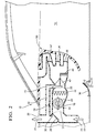
- Fig. 2 illustrates a non-limiting example of an alternative embodiment of the system 10.
- the bypass duct defines the late bypass port 40 at a location downstream of the temperature control valve. While this configuration may require a longer bypass duct and thereby occupy more volume of the cabin 12 than the configuration shown in Fig. 1 , this configuration is advantageous as it helps to ventilate more of the system 10 when operated in the special ventilation mode. That is, more of the HVAC module that houses the blower 18 and the temperature control valve 42 will be ventilated and thereby avoid undesirable heating while the vehicle is parked.
- the system 10 may include one or more cabin valves 50.
- the cabin valve 50 may include a defrost valve 52 that regulates airflow to a windshield, a vent valve 54 that regulates airflow to outlets on a dashboard, and a heat valve 56 that regulates airflow to a floor area of the cabin 12.
- each of the cabin valves is operable to regulate airflow to the cabin through cabin vents (e.g. defrost vent, dashboard vent, floor vent) that correspond with the cabin valves 50.
- cabin vents e.g. defrost vent, dashboard vent, floor vent
- all of the cabin valves 50 are operated to a closed state as illustrated when the cabin is ventilated, i.e.
- the system 10 is operated in the special ventilation mode. Having all of the cabin valves closed is advantageous as the air 22 drawn via the recirculate duct 28 from the cabin will not return to the cabin through the cabin valves 50, thereby providing for the maximum amount of air expelled through the outside air duct 26.
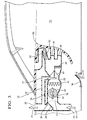
- Fig. 3 shows a non-limiting example of an alternative way to operate the system 10 where one or more of the cabin valves 50 are operated away from a closed state when the cabin is ventilated.
- the phrase 'away from a closed state' means that the various cabin valves can be partially open or fully open as desired.
- the advantage of operating one or more of the cabin valves 50 away from the closed state is that the ducts leading to the various vents are also kept cool.
- having the air 22 flow through defrost valve 52 will help to mix the air in the cabin to avoid stagnation of air near the roof of the cabin 12 so as to promote more uniform ventilated cabin temperature during park.
- the system 10 may include a solar panel (not shown) to keep the battery (not shown) of the vehicle charged if the cabin 12 is ventilated as described herein while the vehicle is parked and the engine is not running. It is also contemplated that the system 10 may include a cabin temperature sensor that is monitored by a controller (not shown) to determine when the special ventilation mode should be used. It is also contemplated that the system 10 may include a timer that the operator can set to indicate when the operator will return to the vehicle so the controller can avoid unnecessarily engaging the special ventilation mode when it is known that the operator will not return for a relatively long time.
- system 10 may include or be in communication with a RF transceiver such as a cellular phone or ON-STAR® transceiver so the operator can communicate with the controller to begin ventilating the cabin because the return of the operator is imminent.
- a RF transceiver such as a cellular phone or ON-STAR® transceiver
- HVAC heating, ventilation, and air-conditioning
- the system 10 configured to ventilate a cabin of a vehicle while the vehicle is parked.
- the addition of the bypass duct 32 and the bypass valve 34 provides the means for the system 10 to engage the special ventilation mode describe herein to ventilate the cabin by drawing air from the cabin via the recirculation-air duct 28 and expelling that air via the outside air duct. If the cabin is ventilated, the system can more quickly achieve a comfortable temperature for the operator of the vehicle, and the maximum cooling capacity of the system 10 may be reduced when compared to HVAC systems that are not able to engage the special ventilation mode described herein.
Landscapes
- Physics & Mathematics (AREA)
- Thermal Sciences (AREA)
- Engineering & Computer Science (AREA)
- Mechanical Engineering (AREA)
- Air-Conditioning For Vehicles (AREA)
Applications Claiming Priority (1)
| Application Number | Priority Date | Filing Date | Title |
|---|---|---|---|
| US14/493,986 US9744829B2 (en) | 2014-09-23 | 2014-09-23 | Vehicle HVAC system with cabin ventilation while parked |
Publications (1)
| Publication Number | Publication Date |
|---|---|
| EP3000636A1 true EP3000636A1 (fr) | 2016-03-30 |
Family
ID=53969198
Family Applications (1)
| Application Number | Title | Priority Date | Filing Date |
|---|---|---|---|
| EP15181424.1A Withdrawn EP3000636A1 (fr) | 2014-09-23 | 2015-08-18 | Système de climatisation de véhicule avec ventilation de cabine pendant le stationnement |
Country Status (3)
| Country | Link |
|---|---|
| US (1) | US9744829B2 (fr) |
| EP (1) | EP3000636A1 (fr) |
| CN (1) | CN105437918A (fr) |
Cited By (3)
| Publication number | Priority date | Publication date | Assignee | Title |
|---|---|---|---|---|
| WO2023275067A1 (fr) * | 2021-06-30 | 2023-01-05 | Atlas Technologies Holding B.V. | Système de régularisation de climatisation de cabine de véhicule |
| NL2028582B1 (en) * | 2021-06-30 | 2023-01-09 | Atlas Technologies Holding Bv | Vehicle cabin climate control system |
| US20230226884A1 (en) * | 2020-07-02 | 2023-07-20 | Atlas Technologies Holding B.V. | Vehicle comprising a thermal conditioning system |
Families Citing this family (10)
| Publication number | Priority date | Publication date | Assignee | Title |
|---|---|---|---|---|
| US20160229257A1 (en) * | 2015-02-10 | 2016-08-11 | Ford Global Technologies, Llc | Vehicle and vehicle cabin air extraction system |
| US9975400B2 (en) * | 2015-06-18 | 2018-05-22 | Ford Global Technologies, Llc | Method of controlling climate in a parked vehicle |
| DE102017215458B4 (de) * | 2017-09-04 | 2023-02-23 | Mahle International Gmbh | Klimaanlage eines Fahrzeugs und Fahrzeug mit einer solchen Klimaanlage |
| US20190265717A1 (en) * | 2018-02-28 | 2019-08-29 | Walmart Apollo, Llc | System and method for remotely receiving deliveries using an autonomous wagon |
| CN108394251A (zh) * | 2018-03-28 | 2018-08-14 | 艾泰斯热系统研发(上海)有限公司 | 反向布置的空调系统及控制方法 |
| JP7287204B2 (ja) * | 2019-09-10 | 2023-06-06 | 株式会社デンソー | 車両の熱交換システム |
| EP3878748B1 (fr) * | 2020-03-12 | 2024-12-18 | Airbus Operations, S.L. | Dispositif d'alimentation en air d'une cabine de véhicule et procédé de fonctionnement d'un tel dispositif |
| FR3111419B1 (fr) * | 2020-06-16 | 2022-06-03 | Valeo Systemes Thermiques | Module d’échange de chaleur comprenant au moins deux échangeurs de chaleur |
| CN112428787B (zh) * | 2020-11-26 | 2023-03-28 | 重庆长安汽车股份有限公司 | 一种汽车乘员舱自动换气的控制方法及系统 |
| EP4635849A1 (fr) * | 2024-04-15 | 2025-10-22 | Goodrich Lighting Systems GmbH & Co. KG | Unité de service de passagers d'aéronef, aéronef comprenant celle-ci et procédé de commande d'une unité de service de passagers d'aéronef |
Citations (2)
| Publication number | Priority date | Publication date | Assignee | Title |
|---|---|---|---|---|
| JP2005001539A (ja) * | 2003-06-12 | 2005-01-06 | Nissan Motor Co Ltd | 車両用空調装置 |
| EP1500534A2 (fr) * | 2003-07-23 | 2005-01-26 | Valeo Climatisation | Dispositif de ventilation pour un véhicule |
Family Cites Families (18)
| Publication number | Priority date | Publication date | Assignee | Title |
|---|---|---|---|---|
| US4155221A (en) * | 1976-12-27 | 1979-05-22 | The Boeing Company | Turbofan engine having variable geometry fan duct |
| US5181553A (en) * | 1987-06-15 | 1993-01-26 | Nissan Motor Company, Limited | Air conditioner system for automotive vehicle with minimum discharge temperature for rear foot outlet |
| FR2690111B1 (fr) * | 1992-04-16 | 1995-08-18 | Valeo Thermique Habitacle | Procede et dispositif de climatisation d'un vehicule electrique. |
| US5669813A (en) * | 1996-05-03 | 1997-09-23 | Ford Motor Company | Apparatus for storing and cooling electronic devices and/or modules in a vehicle |
| FR2761305B1 (fr) * | 1997-03-25 | 1999-06-18 | Valeo Climatisation | Dispositif de chauffage-ventilation pour vehicule automobile a commande selective selon les zones de l'habitacle |
| US7497300B2 (en) * | 2004-03-18 | 2009-03-03 | D Angelo John P | Noise reduction tubes |
| US7137445B2 (en) * | 2004-06-16 | 2006-11-21 | Denso International America, Inc. | HVAC center plate scoop for improved temperature distribution |
| US7310963B2 (en) * | 2005-02-09 | 2007-12-25 | Denso International America, Inc. | Automatic drain docking system for HVAC module drain pipe |
| JP4665229B2 (ja) * | 2005-04-21 | 2011-04-06 | 株式会社ヴァレオサーマルシステムズ | 車両用空調装置 |
| JP5012249B2 (ja) * | 2006-08-07 | 2012-08-29 | 株式会社デンソー | 車両空調用吹出ダクトおよび車両用空調装置 |
| JP4395523B2 (ja) * | 2007-04-18 | 2010-01-13 | 三菱重工業株式会社 | 車両空調装置用吹出しモードドアおよびそれを用いた車両空調装置 |
| JP4395796B2 (ja) * | 2007-07-10 | 2010-01-13 | 株式会社デンソー | 車両用空調装置 |
| US20090071178A1 (en) * | 2007-09-14 | 2009-03-19 | Gm Global Technology Operations, Inc. | Vehicle HVAC and Battery Thermal Management |
| US8926413B2 (en) * | 2008-02-20 | 2015-01-06 | Automotive Components Holdings, Llc | Automotive HVAC alternative bleed path for a vehicle window defrost |
| US10029536B2 (en) * | 2009-05-29 | 2018-07-24 | Honda Motor Co., Ltd. | Integrated front and rear HVAC system |
| JP5473449B2 (ja) * | 2009-07-23 | 2014-04-16 | 三菱重工業株式会社 | 車両用空調装置 |
| JP5482720B2 (ja) * | 2011-04-19 | 2014-05-07 | 株式会社デンソー | 車両用空調装置 |
| US9120366B2 (en) * | 2012-04-27 | 2015-09-01 | Ford Global Technologies, Llc | Monitoring air filter status in automotive HVAC system |
-
2014
- 2014-09-23 US US14/493,986 patent/US9744829B2/en not_active Expired - Fee Related
-
2015
- 2015-08-18 EP EP15181424.1A patent/EP3000636A1/fr not_active Withdrawn
- 2015-09-01 CN CN201510555602.8A patent/CN105437918A/zh active Pending
Patent Citations (2)
| Publication number | Priority date | Publication date | Assignee | Title |
|---|---|---|---|---|
| JP2005001539A (ja) * | 2003-06-12 | 2005-01-06 | Nissan Motor Co Ltd | 車両用空調装置 |
| EP1500534A2 (fr) * | 2003-07-23 | 2005-01-26 | Valeo Climatisation | Dispositif de ventilation pour un véhicule |
Cited By (4)
| Publication number | Priority date | Publication date | Assignee | Title |
|---|---|---|---|---|
| US20230226884A1 (en) * | 2020-07-02 | 2023-07-20 | Atlas Technologies Holding B.V. | Vehicle comprising a thermal conditioning system |
| US12434536B2 (en) * | 2020-07-02 | 2025-10-07 | Lightyear Ipco B.V. | Thermal conditioning system for a vehicle |
| WO2023275067A1 (fr) * | 2021-06-30 | 2023-01-05 | Atlas Technologies Holding B.V. | Système de régularisation de climatisation de cabine de véhicule |
| NL2028582B1 (en) * | 2021-06-30 | 2023-01-09 | Atlas Technologies Holding Bv | Vehicle cabin climate control system |
Also Published As
| Publication number | Publication date |
|---|---|
| US20160082809A1 (en) | 2016-03-24 |
| CN105437918A (zh) | 2016-03-30 |
| US9744829B2 (en) | 2017-08-29 |
Similar Documents
| Publication | Publication Date | Title |
|---|---|---|
| US9744829B2 (en) | Vehicle HVAC system with cabin ventilation while parked | |
| CN103009964B (zh) | 用于机动车辆抽气装置的主动泄压阀 | |
| CN103863058B (zh) | 用于启停发动机的具有改善的空气再循环的车辆hvac系统 | |
| US9707824B2 (en) | Vehicle heat pump air-conditioning system | |
| US20180312039A1 (en) | Airflow control system | |
| US20090283604A1 (en) | Heating System for an Automotive Vehicle | |
| CN103629787B (zh) | 车辆空气调节系统 | |
| JP5609764B2 (ja) | 車両用空調装置 | |
| US10190812B2 (en) | Method and system for reducing the possibility of vehicle heat exchanger freezing | |
| JP2014513645A (ja) | 熱交換器をバイパスする空気流路を含む加熱、換気、および/または空気調和装置 | |
| CN111319421B (zh) | 用于控制空调中的内部/外部空气的系统 | |
| US20150343882A1 (en) | Method and System for Preconditioning a Heating and/or Cooling Unit in a Motor Vehicle | |
| US20160229265A1 (en) | Vehicle speed induced ventilation for motor vehicle | |
| JP5044309B2 (ja) | 車室換気制御装置 | |
| US11820201B2 (en) | Method for controlling vehicle HVAC system | |
| CN107584991A (zh) | 用于车辆的空气调节装置 | |
| CN104943502B (zh) | 车辆舱室的通气系统和方法 | |
| JP5044985B2 (ja) | 車両用空調制御装置 | |
| JP2009035153A (ja) | 車両用空調装置 | |
| KR101776497B1 (ko) | 차량의 개별공조 장치 및 그 제어방법 | |
| KR101659879B1 (ko) | 차량용 공조장치의 제어방법 | |
| US20230068735A1 (en) | Individual air conditioning control system for electric automobile | |
| CN116811514A (zh) | 热管理系统及其控制方法 | |
| CN107696827A (zh) | 车辆 | |
| CN202158637U (zh) | 汽车空调壳体风口防水机构 |
Legal Events
| Date | Code | Title | Description |
|---|---|---|---|
| PUAI | Public reference made under article 153(3) epc to a published international application that has entered the european phase |
Free format text: ORIGINAL CODE: 0009012 |
|
| AK | Designated contracting states |
Kind code of ref document: A1 Designated state(s): AL AT BE BG CH CY CZ DE DK EE ES FI FR GB GR HR HU IE IS IT LI LT LU LV MC MK MT NL NO PL PT RO RS SE SI SK SM TR |
|
| AX | Request for extension of the european patent |
Extension state: BA ME |
|
| RIN1 | Information on inventor provided before grant (corrected) |
Inventor name: GHOSH, DEBASHIS Inventor name: CRAIG, TIMOTHY D. Inventor name: WOLFE IV, EDWARD I. Inventor name: WANG, MINGYU Inventor name: CHOWDHURY, SOURAV |
|
| 17P | Request for examination filed |
Effective date: 20160921 |
|
| RBV | Designated contracting states (corrected) |
Designated state(s): AL AT BE BG CH CY CZ DE DK EE ES FI FR GB GR HR HU IE IS IT LI LT LU LV MC MK MT NL NO PL PT RO RS SE SI SK SM TR |
|
| RAP1 | Party data changed (applicant data changed or rights of an application transferred) |
Owner name: MAHLE INTERNATIONAL GMBH |
|
| 17Q | First examination report despatched |
Effective date: 20180302 |
|
| GRAP | Despatch of communication of intention to grant a patent |
Free format text: ORIGINAL CODE: EPIDOSNIGR1 |
|
| RIC1 | Information provided on ipc code assigned before grant |
Ipc: B60H 1/24 20060101AFI20180711BHEP Ipc: B60H 1/00 20060101ALN20180711BHEP |
|
| INTG | Intention to grant announced |
Effective date: 20180806 |
|
| STAA | Information on the status of an ep patent application or granted ep patent |
Free format text: STATUS: THE APPLICATION IS DEEMED TO BE WITHDRAWN |
|
| 18D | Application deemed to be withdrawn |
Effective date: 20181218 |