EP3000716A1 - Vorrichtung zur Positionierung eines Unterwasserobjekts - Google Patents
Vorrichtung zur Positionierung eines Unterwasserobjekts Download PDFInfo
- Publication number
- EP3000716A1 EP3000716A1 EP14186001.5A EP14186001A EP3000716A1 EP 3000716 A1 EP3000716 A1 EP 3000716A1 EP 14186001 A EP14186001 A EP 14186001A EP 3000716 A1 EP3000716 A1 EP 3000716A1
- Authority
- EP
- European Patent Office
- Prior art keywords
- cable termination
- termination head
- underwater object
- positioning
- engaging device
- Prior art date
- Legal status (The legal status is an assumption and is not a legal conclusion. Google has not performed a legal analysis and makes no representation as to the accuracy of the status listed.)
- Ceased
Links
Images


Classifications
-
- B—PERFORMING OPERATIONS; TRANSPORTING
- B63—SHIPS OR OTHER WATERBORNE VESSELS; RELATED EQUIPMENT
- B63C—LAUNCHING, HAULING-OUT, OR DRY-DOCKING OF VESSELS; LIFE-SAVING IN WATER; EQUIPMENT FOR DWELLING OR WORKING UNDER WATER; MEANS FOR SALVAGING OR SEARCHING FOR UNDERWATER OBJECTS
- B63C11/00—Equipment for dwelling or working underwater; Means for searching for underwater objects
- B63C11/52—Tools specially adapted for working underwater, not otherwise provided for
-
- B—PERFORMING OPERATIONS; TRANSPORTING
- B66—HOISTING; LIFTING; HAULING
- B66C—CRANES; LOAD-ENGAGING ELEMENTS OR DEVICES FOR CRANES, CAPSTANS, WINCHES, OR TACKLES
- B66C1/00—Load-engaging elements or devices attached to lifting or lowering gear of cranes or adapted for connection therewith for transmitting lifting forces to articles or groups of articles
- B66C1/10—Load-engaging elements or devices attached to lifting or lowering gear of cranes or adapted for connection therewith for transmitting lifting forces to articles or groups of articles by mechanical means
- B66C1/62—Load-engaging elements or devices attached to lifting or lowering gear of cranes or adapted for connection therewith for transmitting lifting forces to articles or groups of articles by mechanical means comprising article-engaging members of a shape complementary to that of the articles to be handled
-
- B—PERFORMING OPERATIONS; TRANSPORTING
- B66—HOISTING; LIFTING; HAULING
- B66C—CRANES; LOAD-ENGAGING ELEMENTS OR DEVICES FOR CRANES, CAPSTANS, WINCHES, OR TACKLES
- B66C13/00—Other constructional features or details
- B66C13/02—Devices for facilitating retrieval of floating objects, e.g. for recovering crafts from water
-
- B—PERFORMING OPERATIONS; TRANSPORTING
- B66—HOISTING; LIFTING; HAULING
- B66C—CRANES; LOAD-ENGAGING ELEMENTS OR DEVICES FOR CRANES, CAPSTANS, WINCHES, OR TACKLES
- B66C13/00—Other constructional features or details
- B66C13/04—Auxiliary devices for controlling movements of suspended loads, or preventing cable slack
- B66C13/08—Auxiliary devices for controlling movements of suspended loads, or preventing cable slack for depositing loads in desired attitudes or positions
-
- H—ELECTRICITY
- H02—GENERATION; CONVERSION OR DISTRIBUTION OF ELECTRIC POWER
- H02G—INSTALLATION OF ELECTRIC CABLES OR LINES, OR OF COMBINED OPTICAL AND ELECTRIC CABLES OR LINES
- H02G1/00—Methods or apparatus specially adapted for installing, maintaining, repairing or dismantling electric cables or lines
- H02G1/06—Methods or apparatus specially adapted for installing, maintaining, repairing or dismantling electric cables or lines for laying cables, e.g. laying apparatus on vehicle
- H02G1/10—Methods or apparatus specially adapted for installing, maintaining, repairing or dismantling electric cables or lines for laying cables, e.g. laying apparatus on vehicle in or under water
-
- B—PERFORMING OPERATIONS; TRANSPORTING
- B63—SHIPS OR OTHER WATERBORNE VESSELS; RELATED EQUIPMENT
- B63B—SHIPS OR OTHER WATERBORNE VESSELS; EQUIPMENT FOR SHIPPING
- B63B27/00—Arrangement of ship-based loading or unloading equipment for cargo or passengers
- B63B27/16—Arrangement of ship-based loading or unloading equipment for cargo or passengers of lifts or hoists
- B63B2027/165—Deployment or recovery of underwater vehicles using lifts or hoists
Definitions
- the present invention relates to an apparatus for positioning an underwater object, and relates particularly, but not exclusively, to an apparatus for subsea positioning of a cable termination head into engagement with a subsea receiver frame of a tidal turbine generator.
- a cable termination head to which a cable for transferring power from the turbine generator to shore is connected, needs to form an electrical connection with an undersea receiver frame of the turbine generator.
- Existing methods of installing cable termination heads involve the use of remotely operated vehicles (ROVs), which cannot operate in conditions of high tidal flow.
- ROVs remotely operated vehicles
- the forces encountered by cables connected to the cable termination head often necessitate the use of significant reinforcement in the form of bend restrictors to prevent damage to the cables, which increase the weight of the cable termination head with the cable connected thereto, and make the cable termination head more difficult to connect to the receiver frame.
- Preferred embodiments of the present invention seek to overcome one or more of the above disadvantages of the prior art.
- a positioning apparatus for positioning an underwater object comprising:-
- this provides the advantage of enabling bending forces acting on a cable connected to the underwater object to be reduced while the positioning apparatus is in a first mode thereof, while enabling more effective manipulation of the object to be carried out in the second mode of the apparatus as the object approaches its destination.
- less robust cable protection in the form of bend restrictors is required, for example polyurethane bend restrictors can be used instead of metal bend restrictors, as a result of which the cable and underwater object can be assembled onshore, thereby improving the ease of installation and reliability of the apparatus.
- At least one said engaging device may be adapted to pivot about a plurality of respective said axes relative to the body in said first mode.
- At least one said engaging device may be adapted to slidingly engage the underwater object.
- At least one said engaging device may be adapted to engage the underwater object by means of the weight of the positioning apparatus.
- the apparatus may further comprise latching means for releasably mounting at least one said engaging device to the underwater object.
- the apparatus may further comprise biasing means for biasing said latching means into engagement with the underwater object.
- the latching means may be remotely releasable.
- the apparatus may further comprise actuator means for adjusting the orientation of at least one said engaging device relative to the body.
- the actuator means may be remotely operable.
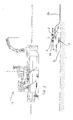
- a positioning apparatus 2 embodying the present invention for locating a first underwater object in the form of a cable termination head 4 in a second underwater object in the form of a receiver frame 6 of a tidal generator apparatus (not shown) located on the seabed 8 has a body 10 which can be lowered to the seabed 8 by a surface vessel 12 and an engaging member in the form of a support 14 for the cable termination head 4 which, in a first mode of the positioning apparatus 2 as shown in Figure 1 , is connected to the body 10 by a gimbal mechanism so that the support 14 can rotate about mutually perpendicular axes 16, 18 ( Figure 5 ) relative to the body 10.
- a cable 20 for transferring power from the tidal generator apparatus to the shore is connected to the cable termination head 4.
- the body 10 of the positioning apparatus 2 is provided with thrusters 22 for controlling the position of the apparatus 2.
- the cable termination head 4 is provided with a protrusion 24 on its upper surface having a recess 26 for receiving locking pins 28 of a latching mechanism provided on the support 14 so that the support 14 can be lowered into latching engagement with the protrusion 24 on the cable termination head 4 while allowing rotation of the support 14 about axis 16 relative to the cable termination head 4.
- the locking pins 28 are spring loaded towards the latching position, and can be released by remote actuation of latching cylinders 30 to withdraw the locking pins 28 to release the support 14 from the protrusion 24. Pivoting of the support 14 about axis 18 relative to the body 10 of the positioning apparatus 2 is controlled by a pitch control cylinder 32.
- the positioning apparatus 2 In an initial condition of the positioning apparatus 2, the positioning apparatus 2 is in its first mode in which the cable termination head 4 can pivot about the first 16 and second 18 axes relative to the body 10 of the positioning apparatus 2.
- the cable termination head 4 can orient itself under the weight of the cable 20 such that bending forces in the cable 20 are minimised.
- This in turn enables less robust bend restrictors such as a polyurethane bend restrictor 34 to be used, as a result of which the cable termination head 4 and bend restrictor 34 can be mounted to the cable 20 in a factory and mounted to a reel (not shown), making installation of the cable 20 more reliable.
- the orientation of the cable termination head 4 relative to the body 10 of the positioning apparatus 2 is fixed by means of the pitch control cylinder 32, as a result of which more accurate location of the cable termination head 4 in the receiver frame 6 can be carried out.
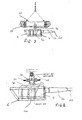
- a locking apparatus 36 has a locking member 38 which extends from the protrusion 24 in the upper surface of the cable termination head 4 to a lower part of the cable termination head 4 where a distal end 40 thereof can be rotated by means of a lock drive motor 42 ( Figure 8 ) to lock the cable termination head 4 to the receiver frame 6.
- the locking member 38 is arranged such that the latching cylinders 30 of the latching mechanism on the positioning apparatus 2 cannot be released from the protrusion 24 unless the locking member 38 is in its locked condition, i.e. locking the cable termination head 4 to the receiver frame 6. This can be achieved either mechanically, or by means of software.
- the positioning apparatus 2 brings the cable termination head 4 mounted thereto, in the second mode of operation of the manipulator apparatus, into engagement with the receiver frame 6.
- the lock drive motor 42 rotates the locking member 38 into its locking condition so that the distal end 40 of the locking member 38 locks the cable termination head 4 in engagement with the receiver frame 6.
- the latching cylinders 30 can be remotely operated to retract the locking pins 28 to release the support 14 from the protrusion 24 on the cable termination head 4 and enable the positioning apparatus 2 to be retrieved to the surface vessel 12.
- the actuator apparatus 48 is mounted to the cable termination head 4 and has an actuator member 50 rotatably mounted via a bearing 52 in a housing 54 of the cable termination head 4 and a body member 56 slidably mounted in the actuator member 50 and supporting a stab plate 58 which in turn supports first electrical terminals 44 on the cable termination head 4 for mating with second electrical terminals 46 on the receiver frame 6.
- the cable termination head 4 is provided with a pair of guide rails 60 for receiving guide pins 62 on the receiver frame 6 to ensure correct alignment of the cable termination head 4 and receiver frame 6.
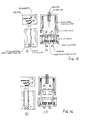
- the body member 56 extending from the stab plate 58 and slidably mounted to actuator member 50 is provided with three pins 64 arranged equiangularly around its external circumference, the pins 64 engaging corresponding grooves 66 on the internal surface of the actuator member 50 as shown in Figure 12(c) .
- the body member 56 is accessible at an upper surface of the cable termination head 4, i.e. at open upper end 68 of the actuator member 50, so that pressure can be applied to the body member 56 by means of a piston 70 located on the positioning apparatus 2, as shown in Figures 10 and 11 .
- a visual indicator 72 is provided at the upper end 68 of the body member 56 and actuator member 50 as shown in Figure 12(d) to indicate the condition of the actuator apparatus 48.
- the first 44 and second 46 electrical terminals are in the state shown in Figures 12(a) and 12 (b) , the pins 64 on the body member 56 are located in upper parts 74 of the respective grooves 66, and the visual indicator 72 indicates that the actuator apparatus 48 is in the de-mated condition.
- the piston 70 on the positioning apparatus 2 is extended as shown in Figure 11 , as a result of which the body member 56 is urged downwards relative to the actuator member 50 against the action of springs 76 to bring the first 44 and second 46 electrical terminals into engagement with each other as shown in Figure 13(a) .
- Movement of the pins 64 to lower parts 78 of the grooves 66 causes rotation of the actuator member 50 relative to the body member 56 such that the visual indicator 72 rotates to indicate that the actuator apparatus 48 is in the mated condition as shown in Figure 13(c) .
- the piston 70 is then retracted, as a result of which the pins 64 are moved by the action of the springs 76 and compression springs 80 into recesses 82 in the grooves 66 in the actuator member 50 to retain the first 44 and second 46 electrical terminals in their locked condition.
- further movement of the pins 64 along the grooves 66 to the recesses 82 causes further rotation of the actuator member 50 in the cable termination head 4, so that the visual indicator 72 then indicates that the apparatus is in the locked condition as shown in Figure 14(c) .
- the piston 70 is extended again to urge the body member 56 downwards relative to the actuator member 50, so that the pins 64 can now access the vertical portions of the corresponding grooves 66 in the actuator member 50. Further rotation of the actuator member 50 in the cable termination head 4 indicates the condition shown in Figure 15(c) .
- the springs 76, 80 can now urge the body member 56 (together with the first electrical terminals 44) upwards so that the pins 64 are located in the upper portions 74 of the grooves 66 and the visual indicator 72 rotates further in the cable termination head 4 to indicate that the actuator apparatus 48 is again in the de-mated condition as shown in Figure 16(c) thereby restoring the condition shown in Figure 12(a) to 12(c) .
Landscapes
- Engineering & Computer Science (AREA)
- Mechanical Engineering (AREA)
- Ocean & Marine Engineering (AREA)
- Laying Of Electric Cables Or Lines Outside (AREA)
Priority Applications (1)
| Application Number | Priority Date | Filing Date | Title |
|---|---|---|---|
| EP14186001.5A EP3000716A1 (de) | 2014-09-23 | 2014-09-23 | Vorrichtung zur Positionierung eines Unterwasserobjekts |
Applications Claiming Priority (1)
| Application Number | Priority Date | Filing Date | Title |
|---|---|---|---|
| EP14186001.5A EP3000716A1 (de) | 2014-09-23 | 2014-09-23 | Vorrichtung zur Positionierung eines Unterwasserobjekts |
Publications (1)
| Publication Number | Publication Date |
|---|---|
| EP3000716A1 true EP3000716A1 (de) | 2016-03-30 |
Family
ID=51625826
Family Applications (1)
| Application Number | Title | Priority Date | Filing Date |
|---|---|---|---|
| EP14186001.5A Ceased EP3000716A1 (de) | 2014-09-23 | 2014-09-23 | Vorrichtung zur Positionierung eines Unterwasserobjekts |
Country Status (1)
| Country | Link |
|---|---|
| EP (1) | EP3000716A1 (de) |
Cited By (5)
| Publication number | Priority date | Publication date | Assignee | Title |
|---|---|---|---|---|
| CN109928299A (zh) * | 2019-04-04 | 2019-06-25 | 哈尔滨工程大学 | 一种可自动挂钩和脱钩的遥控式uuv布放回收机构及方法 |
| WO2020187381A1 (en) * | 2019-03-20 | 2020-09-24 | Harco Aps | An apparatus for launch and recovery of a submersible vessel from and to an off-shore site |
| NO20221134A1 (en) * | 2022-10-21 | 2024-04-22 | Subsea 7 Norway As | Connections to subsea electrical equipment |
| WO2024084093A1 (en) | 2022-10-21 | 2024-04-25 | Subsea 7 Norway As | Connections to subsea electrical equipment |
| US12252223B2 (en) | 2019-08-19 | 2025-03-18 | Noble Drilling A/S | Offshore drilling vessel with an external cable connection and method therefor |
Citations (4)
| Publication number | Priority date | Publication date | Assignee | Title |
|---|---|---|---|---|
| GB2324416A (en) * | 1997-04-18 | 1998-10-21 | Alsthom Cge Alcatel | Moving an elongate article between a horizontal and a vertical position |
| US20030026676A1 (en) * | 2001-07-24 | 2003-02-06 | Grinsted Timothy William | Load handling device |
| GB2486900A (en) * | 2010-12-29 | 2012-07-04 | M S C M Ltd | Subsea Stab Plate with Tilt and Slide Mechanism |
| EP2722948A1 (de) * | 2012-10-19 | 2014-04-23 | Soil Machine Dynamics Limited | Unterstützungsvorrichtung für miteinander verbundene Komponenten |
-
2014
- 2014-09-23 EP EP14186001.5A patent/EP3000716A1/de not_active Ceased
Patent Citations (4)
| Publication number | Priority date | Publication date | Assignee | Title |
|---|---|---|---|---|
| GB2324416A (en) * | 1997-04-18 | 1998-10-21 | Alsthom Cge Alcatel | Moving an elongate article between a horizontal and a vertical position |
| US20030026676A1 (en) * | 2001-07-24 | 2003-02-06 | Grinsted Timothy William | Load handling device |
| GB2486900A (en) * | 2010-12-29 | 2012-07-04 | M S C M Ltd | Subsea Stab Plate with Tilt and Slide Mechanism |
| EP2722948A1 (de) * | 2012-10-19 | 2014-04-23 | Soil Machine Dynamics Limited | Unterstützungsvorrichtung für miteinander verbundene Komponenten |
Cited By (7)
| Publication number | Priority date | Publication date | Assignee | Title |
|---|---|---|---|---|
| WO2020187381A1 (en) * | 2019-03-20 | 2020-09-24 | Harco Aps | An apparatus for launch and recovery of a submersible vessel from and to an off-shore site |
| US12172733B2 (en) | 2019-03-20 | 2024-12-24 | Arcim Aps | Apparatus for launch and recovery of a submersible vessel from and to an off-shore site |
| CN109928299A (zh) * | 2019-04-04 | 2019-06-25 | 哈尔滨工程大学 | 一种可自动挂钩和脱钩的遥控式uuv布放回收机构及方法 |
| US12252223B2 (en) | 2019-08-19 | 2025-03-18 | Noble Drilling A/S | Offshore drilling vessel with an external cable connection and method therefor |
| NO20221134A1 (en) * | 2022-10-21 | 2024-04-22 | Subsea 7 Norway As | Connections to subsea electrical equipment |
| WO2024084093A1 (en) | 2022-10-21 | 2024-04-25 | Subsea 7 Norway As | Connections to subsea electrical equipment |
| NO348118B1 (en) * | 2022-10-21 | 2024-08-26 | Subsea 7 Norway As | Connections to subsea electrical equipment |
Similar Documents
| Publication | Publication Date | Title |
|---|---|---|
| EP3000716A1 (de) | Vorrichtung zur Positionierung eines Unterwasserobjekts | |
| US9482061B2 (en) | Subsea connector assembly | |
| US20120168168A1 (en) | System and method for connection and installation of underwater lines | |
| EP1448923B1 (de) | Unterwasserverbindungsvorrichtung | |
| EP2955096B1 (de) | Gruppe um Festmacheleinen mit einem Anker zu vertäuen und umgesetztes Verfahren mit der gennanten Gruppe. | |
| EP2665958B1 (de) | Vorrichtung und verfahren zur verbindung von untersee-rohrleitungen | |
| IE46245B1 (en) | Re-entry system for a subsea station and method of servicing such a system | |
| US20160036160A1 (en) | Method for installing of a wet mateable connection assembly for electrical and/or optical cables | |
| BR112013026471B1 (pt) | Conector elétrico submarino para conectar infraestrutura de sistemas de controle ou alimentação | |
| US20220107168A1 (en) | Strain monitor | |
| EP3008328B1 (de) | Energieerzeugungsvorrichtung | |
| EP3072195B1 (de) | Unterwasserkabel-einrastsystem | |
| EP3000715A1 (de) | Arretierungsvorrichtung für Unterwasserobjekt | |
| EP3000960A1 (de) | Aktuator zur Herstellung einer elektrischen Unterwasserverbindung | |
| KR20250116752A (ko) | 해저 어셈블리의 암형 커넥터용 래치 메커니즘 | |
| WO2010009510A1 (en) | A tool and method | |
| US9394748B2 (en) | Riser-mounted guide assembly for umbilical deployment | |
| EP4331062B1 (de) | Verbinderkoppler | |
| EP2722948A1 (de) | Unterstützungsvorrichtung für miteinander verbundene Komponenten | |
| GB2519943A (en) | Apparatus and method | |
| EP0335218B1 (de) | Kettenförmige Unterwasserkabel | |
| GB2522444A (en) | Lifting frame | |
| EP3841275B1 (de) | Zangenkassetten-positioniervorrichtung | |
| US20160258552A1 (en) | Device for lowering or retrieval of a pipeline at the seabed | |
| NO20160767A1 (en) | A device for operation on a wellhead of a hydrocarbon well |
Legal Events
| Date | Code | Title | Description |
|---|---|---|---|
| PUAI | Public reference made under article 153(3) epc to a published international application that has entered the european phase |
Free format text: ORIGINAL CODE: 0009012 |
|
| AK | Designated contracting states |
Kind code of ref document: A1 Designated state(s): AL AT BE BG CH CY CZ DE DK EE ES FI FR GB GR HR HU IE IS IT LI LT LU LV MC MK MT NL NO PL PT RO RS SE SI SK SM TR |
|
| AX | Request for extension of the european patent |
Extension state: BA ME |
|
| STAA | Information on the status of an ep patent application or granted ep patent |
Free format text: STATUS: THE APPLICATION HAS BEEN REFUSED |
|
| 18R | Application refused |
Effective date: 20160506 |