EP3000742B1 - Recipient en matiere synthetique pouvant etre comprime a l'aide d'un fond - Google Patents
Recipient en matiere synthetique pouvant etre comprime a l'aide d'un fond Download PDFInfo
- Publication number
- EP3000742B1 EP3000742B1 EP15184719.1A EP15184719A EP3000742B1 EP 3000742 B1 EP3000742 B1 EP 3000742B1 EP 15184719 A EP15184719 A EP 15184719A EP 3000742 B1 EP3000742 B1 EP 3000742B1
- Authority
- EP
- European Patent Office
- Prior art keywords
- container
- base
- cup
- region
- contact element
- Prior art date
- Legal status (The legal status is an assumption and is not a legal conclusion. Google has not performed a legal analysis and makes no representation as to the accuracy of the status listed.)
- Not-in-force
Links
- 239000004033 plastic Substances 0.000 title claims description 13
- 229920003023 plastic Polymers 0.000 title claims description 13
- 238000007906 compression Methods 0.000 claims description 10
- 230000006835 compression Effects 0.000 claims description 6
- 239000007788 liquid Substances 0.000 claims description 6
- 239000000463 material Substances 0.000 claims description 6
- 239000004698 Polyethylene Substances 0.000 claims description 4
- 239000004743 Polypropylene Substances 0.000 claims description 4
- 229920000573 polyethylene Polymers 0.000 claims description 4
- -1 polypropylene Polymers 0.000 claims description 4
- 229920001155 polypropylene Polymers 0.000 claims description 4
- 239000011796 hollow space material Substances 0.000 claims 2
- 238000000465 moulding Methods 0.000 description 6
- 238000000034 method Methods 0.000 description 2
- 238000004806 packaging method and process Methods 0.000 description 2
- 230000002093 peripheral effect Effects 0.000 description 2
- 230000003014 reinforcing effect Effects 0.000 description 2
- 230000006978 adaptation Effects 0.000 description 1
- XAGFODPZIPBFFR-UHFFFAOYSA-N aluminium Chemical compound [Al] XAGFODPZIPBFFR-UHFFFAOYSA-N 0.000 description 1
- 229910052782 aluminium Inorganic materials 0.000 description 1
- 238000006243 chemical reaction Methods 0.000 description 1
- 238000011109 contamination Methods 0.000 description 1
- 230000001419 dependent effect Effects 0.000 description 1
- 238000011161 development Methods 0.000 description 1
- 230000018109 developmental process Effects 0.000 description 1
- 238000005553 drilling Methods 0.000 description 1
- 238000004519 manufacturing process Methods 0.000 description 1
- 239000007769 metal material Substances 0.000 description 1
- XLYOFNOQVPJJNP-UHFFFAOYSA-N water Substances O XLYOFNOQVPJJNP-UHFFFAOYSA-N 0.000 description 1
Images



Classifications
-
- B—PERFORMING OPERATIONS; TRANSPORTING
- B65—CONVEYING; PACKING; STORING; HANDLING THIN OR FILAMENTARY MATERIAL
- B65D—CONTAINERS FOR STORAGE OR TRANSPORT OF ARTICLES OR MATERIALS, e.g. BAGS, BARRELS, BOTTLES, BOXES, CANS, CARTONS, CRATES, DRUMS, JARS, TANKS, HOPPERS, FORWARDING CONTAINERS; ACCESSORIES, CLOSURES, OR FITTINGS THEREFOR; PACKAGING ELEMENTS; PACKAGES
- B65D35/00—Pliable tubular containers adapted to be permanently or temporarily deformed to expel contents, e.g. collapsible tubes for toothpaste or other plastic or semi-liquid material; Holders therefor
- B65D35/02—Body construction
- B65D35/04—Body construction made in one piece
- B65D35/08—Body construction made in one piece from plastics material
-
- B—PERFORMING OPERATIONS; TRANSPORTING
- B65—CONVEYING; PACKING; STORING; HANDLING THIN OR FILAMENTARY MATERIAL
- B65D—CONTAINERS FOR STORAGE OR TRANSPORT OF ARTICLES OR MATERIALS, e.g. BAGS, BARRELS, BOTTLES, BOXES, CANS, CARTONS, CRATES, DRUMS, JARS, TANKS, HOPPERS, FORWARDING CONTAINERS; ACCESSORIES, CLOSURES, OR FITTINGS THEREFOR; PACKAGING ELEMENTS; PACKAGES
- B65D1/00—Rigid or semi-rigid containers having bodies formed in one piece, e.g. by casting metallic material, by moulding plastics, by blowing vitreous material, by throwing ceramic material, by moulding pulped fibrous material or by deep-drawing operations performed on sheet material
- B65D1/02—Bottles or similar containers with necks or like restricted apertures, designed for pouring contents
- B65D1/0223—Bottles or similar containers with necks or like restricted apertures, designed for pouring contents characterised by shape
- B65D1/0292—Foldable bottles
-
- B—PERFORMING OPERATIONS; TRANSPORTING
- B65—CONVEYING; PACKING; STORING; HANDLING THIN OR FILAMENTARY MATERIAL
- B65D—CONTAINERS FOR STORAGE OR TRANSPORT OF ARTICLES OR MATERIALS, e.g. BAGS, BARRELS, BOTTLES, BOXES, CANS, CARTONS, CRATES, DRUMS, JARS, TANKS, HOPPERS, FORWARDING CONTAINERS; ACCESSORIES, CLOSURES, OR FITTINGS THEREFOR; PACKAGING ELEMENTS; PACKAGES
- B65D21/00—Nestable, stackable or joinable containers; Containers of variable capacity
- B65D21/02—Containers specially shaped, or provided with fittings or attachments, to facilitate nesting, stacking, or joining together
- B65D21/0209—Containers specially shaped, or provided with fittings or attachments, to facilitate nesting, stacking, or joining together stackable or joined together one-upon-the-other in the upright or upside-down position
-
- B—PERFORMING OPERATIONS; TRANSPORTING
- B65—CONVEYING; PACKING; STORING; HANDLING THIN OR FILAMENTARY MATERIAL
- B65D—CONTAINERS FOR STORAGE OR TRANSPORT OF ARTICLES OR MATERIALS, e.g. BAGS, BARRELS, BOTTLES, BOXES, CANS, CARTONS, CRATES, DRUMS, JARS, TANKS, HOPPERS, FORWARDING CONTAINERS; ACCESSORIES, CLOSURES, OR FITTINGS THEREFOR; PACKAGING ELEMENTS; PACKAGES
- B65D21/00—Nestable, stackable or joinable containers; Containers of variable capacity
- B65D21/02—Containers specially shaped, or provided with fittings or attachments, to facilitate nesting, stacking, or joining together
- B65D21/0209—Containers specially shaped, or provided with fittings or attachments, to facilitate nesting, stacking, or joining together stackable or joined together one-upon-the-other in the upright or upside-down position
- B65D21/023—Closed containers provided with local cooperating elements in the top and bottom surfaces, e.g. projection and recess
-
- B—PERFORMING OPERATIONS; TRANSPORTING
- B65—CONVEYING; PACKING; STORING; HANDLING THIN OR FILAMENTARY MATERIAL
- B65D—CONTAINERS FOR STORAGE OR TRANSPORT OF ARTICLES OR MATERIALS, e.g. BAGS, BARRELS, BOTTLES, BOXES, CANS, CARTONS, CRATES, DRUMS, JARS, TANKS, HOPPERS, FORWARDING CONTAINERS; ACCESSORIES, CLOSURES, OR FITTINGS THEREFOR; PACKAGING ELEMENTS; PACKAGES
- B65D23/00—Details of bottles or jars not otherwise provided for
- B65D23/001—Supporting means fixed to the container
-
- B—PERFORMING OPERATIONS; TRANSPORTING
- B65—CONVEYING; PACKING; STORING; HANDLING THIN OR FILAMENTARY MATERIAL
- B65D—CONTAINERS FOR STORAGE OR TRANSPORT OF ARTICLES OR MATERIALS, e.g. BAGS, BARRELS, BOTTLES, BOXES, CANS, CARTONS, CRATES, DRUMS, JARS, TANKS, HOPPERS, FORWARDING CONTAINERS; ACCESSORIES, CLOSURES, OR FITTINGS THEREFOR; PACKAGING ELEMENTS; PACKAGES
- B65D25/00—Details of other kinds or types of rigid or semi-rigid containers
- B65D25/28—Handles
Definitions
- the present invention relates to a container and in particular a plastic container.
- plastic containers are known from the prior art. These plastic containers have different filling volumes.
- compressible containers are known from the prior art, the contents of which can be removed by compression of the container.
- a dispensing system of the Applicant PET bottles BEVkeg
- BEVkeg Applicant PET bottles
- the dispensing system of the Applicant PET bottles are emptied by reshaping the container wall and the container shoulders.
- the dispensing system specially adapted to the container moldings (in particular stamp) are used.
- these moldings are executed on one side as a stamp to put the container wall to the inside and on the other side of the container these moldings are designed as supporting cups, in which in particular a bottom portion of the plastic containers to be emptied.
- these moldings are integrated into a dispenser and therefore adapted to the respective container shape and container size. An exchange of these moldings is relatively difficult, which makes a conversion to other containers considerably more difficult.
- the present invention is therefore an object of the invention to facilitate such interchangeability of containers. This object is achieved by the subject of independent claim 1. Advantageous embodiments and further developments are the subject of the dependent claims.
- a container according to the invention in particular a plastic container, has a bottom region and a base body adjoining this bottom region, which is suitable for receiving a liquid volume (in particular together with the bottom region) and furthermore an opening region, wherein the container is removed along its longitudinal direction to remove it the container befindaji liquid is compressible.
- a bottom cup is arranged on the bottom area, which forms a standing surface for the container and which can also serve as a stamp element and / or stamp counter element (i.e., as an element which cooperates with a stamp) for compressing the container during compression of the container.
- the bottom cup is preferably designed such that a stability is given on a flat ground or ground.
- the bottom cup of a harder material than the bottom portion of the container, so that in the compression process, not the bottom cup is substantially deformed, but the bottom part, which is pressed into this cup. It is possible that the bottom cup can be arranged together with the container in a dispensing system and centered.
- the bottom cup is designed such that it causes a support of the container during a forming process of the container and in particular during a taking place for the purpose of emptying forming operation.
- the bottom cup is a bottom contact element which bears against the bottom area of the container. It is not absolutely necessary that the bottom cup is completely closed in the circumferential direction. This means that the base cup may possibly also have openings in its wall.
- the bottom region, the base body and the mouth region of the container are integrally formed.
- the container has an internal volume which is greater than 5I, preferably greater than 10I, preferably greater than 15I and preferably greater than 20I. Particularly preferred is a container with an internal volume of 30I.
- the container is particularly preferably a blow-molded container, in particular a stretch blow-molded container.
- the container is made of PET.
- the bottom cup is arranged by means of at least one fastening means on the bottom portion of the container. It is possible, for example, that this floor cup is glued to the floor area and / or clipped. Since, according to experience, the material of the large PET container still expands slightly, the container is naturally “pressed in” into the base cup, which in this sense is to be understood as "clinging".
- At least a portion of the body of the container which is in an uncompressed state of the container outside a cavity surrounded by the bottom cup, is in a compressed state within the cavity surrounded by the bottom cup.
- a portion of the container can be compressed in the cavity surrounded by the bottom cup.
- this is a shoulder and / or mouth region of the container, which can be pushed into the bottom area or the cavity surrounded by the bottom cup.
- the plastic container is designed in such a way that it can be compressed in a defined manner relative to a fold. In this case, a circumferential fold or fold is formed during compression and the container can be folded so.
- the mouth region of the container is folded into the bottom region, so that the above-mentioned circumferential folding edge is formed.
- the bottom portion of the container is formed such that the container could not be placed on the bottom portion standing on a flat surface.
- the bottom area could have a hemispherical cross-section.
- at least one cavity is formed between the bottom cup and the bottom region of the container, and preferably a circumferential cavity is formed between the bottom region of the container and the bottom cup.
- a radially inner region of the bottom cup rests directly against the bottom region of the container and / or preferably also a peripheral edge of the bottom cup rests directly against the bottom region of the container. Between this central area and the peripheral edge, a region can be formed, in which the bottom cup is spaced from the bottom area or the surface of the bottom area.
- this spaced area is annular with respect to an axis of symmetry or longitudinal direction of the plastic container.
- the region which is at a distance from the bottom region preferably forms a base surface of the bottom cup.
- the bottom cup may have an annular stand body. This annular body can also form a circumferential cavity.
- an inner wall of the base cup facing the bottom region of the container is adapted, at least in sections, to a contact element which serves for compressing the container and which is movable relative to the bottom region in a longitudinal direction of the container.
- a contact element is arranged at the mouth region of the container, for example glued or snapped on.
- this investment element may be, for example, a support member, which also serves to carry the container.
- this contact element can also be glued to the mouth or shoulder region of the container.
- this abutment element can also be held by a mouth region, such as a support ring of the container, e.g. via a clip connection.
- the contact element is designed as a stamp member and the container is thus compressible between the bottom cup and this second punch member.
- the inner surface of the contact element facing the base cup it is advantageous for the inner surface of the contact element facing the base cup to have the geometry of the corresponding opposite one Inner surface of the bottom cup adapted to reduce in the manner mentioned above, the container volume as best as possible.
- a surface of the base cup which bears at least partially on the bottom region of the container and a surface of the contact element fitting at least partially at the mouth region of the container are geometrically matched to one another so that when the contact element and the base cup are in contact with one another between these surfaces Distance is at least partially defined essentially only by a wall of the container. This means that in these sections, the container is compressed so that a maximum emptying is possible.
- both the said surface of the base cup lying against the bottom region of the container could be spherical in sections, as could the corresponding surface of the contact element.
- the contact element is geometrically adapted to the bottom cup, that two similar containers (which are provided with bottom cup and contact element) in a longitudinal direction of the containers are stacked one above the other.
- these so cooperating surfaces of the contact element and the bottom cup are advantageously optimized so that in a stacked state no or only as little stress is exerted on the mouth of the containers.
- the second contact element can also serve for receiving further elements for the dispensing operation, such as for receiving a (one-way) dispensing line.
- the contact element has an opening through which a mouth portion of the container can be guided. Furthermore, preferably, the contact element has a cavity into which the above-mentioned elements of a dispensing device can be integrated or stored. However, said cavity can also be formed both by wall regions of the container and by wall regions of the contact element.
- the base cup and / or the contact element are made of a material which is selected from a group of plastic materials, which in particular contains polypropylene (PP) or polyethylene (PE).
- PP polypropylene
- PE polyethylene
- the bottom cup and / or the contact element would also be conceivable as a reusable solution.
- metallic materials in particular die-cast aluminum.
- the bottom cup is designed to be capable of supporting during the forming process, i. emptying the container.
- a sticking or snapping possible which can be done on the hull or on a separate form of the container.
- the contact element or the punch is preferably located on the shoulder of the container and can be fixed on the support ring.
- a contact surface of the contact element is preferably designed so that the container weight can be stacked several times over the internal pressure of the container.
- the abutment element can be designed so that it can be extended, so that interventions for carrying are present and / or such that a cavity can be closed, for example, to receive a one-way line.
- the bottom cup and the contact element are matched to one another such that in a stacked state, the closure of the container is not excessively loaded.
- these elements can be designed such that a force flow, in particular a force flow in a vertical direction does not extend beyond the container closure or areas of the container closure.
- the container closure could be withdrawn in the longitudinal direction of the container relative to the contact element.
- the ground cup provides a strong transport protection when the container is transported by hand.
- the container bottom is so protected from damage that, for example, even with rough handling the container is not scratched or injured in a critical area so that it is leaking.
- a rough treatment could be, for example, the hard placement of containers on a floor or the grinding of a (often up to 20 kilos) container over the ground.
- the base cup and the contact element are preferably made waterproof and preferably any puddles are prevented by drilling, in particular holes in the bottom cup.
- the good stability makes the dispensing system more user-friendly.
- the container can be easily placed on a platform.
- a preferably provided carrying handle on the container facilitates carrying and positioning on a platform.
- This carrying handle can be formed in the contact element.
- the abutment element could have a body extending in the circumferential direction with respect to the longitudinal direction of the container, in which holding sections such as grip recesses or the like are also formed.
- the container can expand over time and temperature and thus strengthen the press fit within the bottom cup.
- Another advantage of a dispensing system to be used is that when the base cup and the plant segment or the stamp are changed with the container, a format change is possible. Thus, not only can different volumes be tapped, but also different shapes can be used to allow for some freedom of individual container design. So-called branding is also possible. If molded parts are attached to the container at both ends, the container will feel even more than keg kegs, and thus higher market acceptance may result. The biggest advantage is the cost saving, which not only follows from the reduced packaging, but it can also be saved in the dispensing costs.
- FIG. 1 shows a side view of a container according to the invention 1.
- This container 1 has a bottom portion 6, to which a base body 4 is connected.
- an end or shoulder region 2 adjoins this basic body 4.
- the majority of a liquid contained in the container is in the area surrounded by the body of the container area.
- the reference character L denotes a longitudinal direction of the container, along which the container 1 is also compressed.
- the reference numeral 10 denotes a bottom cup which is disposed on the bottom portion. It can be seen that this base cup lies directly against the bottom region 6 in a region A1 and is spaced from the bottom region in a further region A2.
- the region A1, along which the bottom cup 10 rests against the bottom region 6, is designed to be rotationally symmetrical or circular (viewed in a projection along the longitudinal direction L).
- the surface A2, along which the bottom cup is not applied to the bottom portion 6 is annular and extends here curved and passes in this section in the base body 4 over.
- the reference numeral 8 denotes a contact element, which rests against the shoulder region of the container. In this case, again a region A3 can be seen, in which this contact element bears against the shoulder 2 of the container.
- the reference numeral 14 denotes a closure, to which the container is arranged. It is possible that this contact element 8 is held between the shoulder region 2 and a support ring 18 of the container. In a compression process of the container 1, this contact element 8 acts as a stamp and in particular with the bottom cup 10 together. Thus, the container is compressed in particular in its longitudinal direction between the contact element and the bottom cup.
- the reference numeral 22 refers to a base portion of the bottom cup 10 and the reference numeral 26 to a circumferential and vertical wall portion.
- FIG. 2 shows a representation of two superposed containers 1. It can be seen that the system part 8 of the lower container cooperates with a bottom cup 10 of the container arranged above or can intermesh. It is possible that by corresponding projections and webs, which are adapted to corresponding recesses of the bottom cup (or vice versa) such a meshing of two superimposed containers is made possible. Thus, as mentioned above, an upper side of the contact element is adapted to an underside of the base cup (in particular a further container).
- FIG. 3 shows a representation in which here by means of a stamp member, the container was compressed or folded.
- the reference numeral 50 denotes a punch which serves to fold the container.
- this is a stamp that is not part of a dispensing system, but that is used to reshape the plastic containers to make them transportable.
- the container is manufactured (eg blow-molded) and then by means of a compression device, in particular by means of the punch 50, is compressed, so that the container can be transported easier and more space-saving.
- FIG. 4 shows a variant of the design of the ground cup.
- the contact element and the bottom cup could be configured alsklippbar.
- a snap element in the center of the container bottom is considered, to which the bottom cup can be attached or snapped.
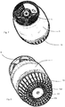
- FIG. 5 shows a perspective view of a container according to the invention. Again, you can see the bottom cup 10 and the main body 4 and the shoulder area 8. Also, in turn, the closure 14 can be seen, which serves to seal the container. At the same time, the abutment element 8 can also serve for receiving further elements, such as a dispensing line.
- FIG. 6 shows a representation of two nested containers.
- the representation of a container essentially corresponds to the FIG. 3 , which shows that the two containers and several containers can be stacked together, so that in this way a transport of the containers is facilitated.
- FIG. 7 shows a further perspective view of a container.
- the container in its entirety has a bulbous structure, so that for the purpose of compressing both the contact element and the bottom cup 10 can be used and that between these two elements located container or its body can be compressed.
- FIG. 8 shows another illustration from below on the in FIG. 7 shown container. It can be seen here that the bottom cup 10 has an annular portion 102, which also serves as a base. Furthermore, a plurality of reinforcing ribs 104 can be seen, which connect the ring 102 with a central region 106. As mentioned above, the region 106 preferably lies flat against the bottom surface of the own plastic container.
- FIG. 9 shows a sectional view of a container 1 in a compressed state. It can be seen here again that the bottom region 6 rests in the bottom cup. Also, again, the folding edge 32 can be seen, along which the container has been folded.
- the reference numeral 24 denotes an opening region or an opening of the container and the reference numeral 28 an annular receiving portion of the contact element 8, which surrounds the mouth region.
- fixing sections 82 which are arranged on the application segment and which abut from below on a support ring 18 of the container, so as to fix the application segment to the container.
- a downwardly facing surface 86 of the abutment element is adapted to an outer surface 88 of the bottom cup 10 in order, as mentioned above, to empty the container as completely as possible.
- FIG. 10 shows a variety of stacked containers. It can be seen that with the exception of a base pallet 72, the containers 10 do not require any further pallets, but can be stacked directly one above the other.
Landscapes
- Engineering & Computer Science (AREA)
- Mechanical Engineering (AREA)
- Ceramic Engineering (AREA)
- Packages (AREA)
- Stackable Containers (AREA)
- Containers Having Bodies Formed In One Piece (AREA)
Claims (5)
- Récipient (1), en particulier récipient en matière plastique (1) avec une zone de fond (6), un corps de base (4) se raccordant à cette zone de fond (6) qui convient à la réception d'un volume de liquide, et avec une zone d'embouchure (2), et un élément d'appui (8) agencé contre la zone d'embouchure (2),
dans lequel le récipient (1) est compressible le long de sa direction longitudinale (L) pour l'extraction d'un liquide se trouvant dans le récipient (1) et contre la zone de fond (6) est agencé un gobelet de fond (10) qui forme une surface d'assise (102) pour le récipient (1), et une paroi intérieure tournée vers la zone de fond (6) du récipient (1) du gobelet de fond (10) est ajustée au moins par endroits à l'élément d'appui (8), lequel sert à comprimer le récipient (1) et lequel est mobile vis-à-vis de la zone de fond (6) dans une direction longitudinale (L) du récipient (1), de sorte que le gobelet de fond (10) et l'élément d'appui (8) interagissent lors de l'opération de compression du récipient (1), et au moins une partie du corps de base (4) du récipient, qui se trouve à l'extérieur d'un espace libre entouré par le gobelet de fond (10) dans un état non comprimé du récipient (1), se trouve à l'intérieur de l'espace libre entouré par le gobelet de fond (10) dans un état comprimé,
dans lequel la zone d'embouchure (2) du récipient (1) est repliée dans la zone de fond (6), de sorte que pendant la compression une arête de pliage (32) périphérique soit formée,
caractérisé en ce que
le gobelet de fond (10) est agencé contre la zone de fond (6) au moyen d'au moins un moyen de fixation. - Récipient (1) selon la revendication 1,
caractérisé en ce que
l'élément d'appui (8) est formé en tant qu'élément de poinçon et le récipient (1) est compressible entre le gobelet de fond (10) et cet élément de poinçon. - Récipient (1) selon la revendication 1,
caractérisé en ce que
l'élément d'appui (8) est ajusté géométriquement sur le gobelet de fond (6) de telle sorte que deux récipients similaires soient empilables l'un sur l'autre dans une direction longitudinale (L) des récipients. - Récipient (1) selon au moins l'une des revendications précédentes, caractérisé en ce que
l'élément transporteur présente une ouverture (28) à travers laquelle une partie d'embouchure du récipient (1) peut être dirigée. - Récipient (1) selon au moins l'une des revendications précédentes, caractérisé en ce que
le gobelet de fond (10) et/ou l'élément d'appui (8) sont fabriqués dans un matériau qui est sélectionné dans un groupe de matériaux en matière plastique, lequel contient en particulier du polypropylène (PP) ou du polyéthylène (PE).
Applications Claiming Priority (1)
| Application Number | Priority Date | Filing Date | Title |
|---|---|---|---|
| DE102014113915.1A DE102014113915A1 (de) | 2014-09-25 | 2014-09-25 | Komprimierbares Kunststoffbehältnis mit Bodentasse |
Publications (2)
| Publication Number | Publication Date |
|---|---|
| EP3000742A1 EP3000742A1 (fr) | 2016-03-30 |
| EP3000742B1 true EP3000742B1 (fr) | 2018-10-24 |
Family
ID=54106232
Family Applications (1)
| Application Number | Title | Priority Date | Filing Date |
|---|---|---|---|
| EP15184719.1A Not-in-force EP3000742B1 (fr) | 2014-09-25 | 2015-09-10 | Recipient en matiere synthetique pouvant etre comprime a l'aide d'un fond |
Country Status (4)
| Country | Link |
|---|---|
| US (1) | US9845178B2 (fr) |
| EP (1) | EP3000742B1 (fr) |
| CN (1) | CN105460346B (fr) |
| DE (1) | DE102014113915A1 (fr) |
Families Citing this family (10)
| Publication number | Priority date | Publication date | Assignee | Title |
|---|---|---|---|---|
| DE102014113915A1 (de) * | 2014-09-25 | 2016-03-31 | Krones Aktiengesellschaft | Komprimierbares Kunststoffbehältnis mit Bodentasse |
| GB2560024B (en) | 2017-02-27 | 2020-04-22 | Petainer Large Container Ip Ltd | Keg chime |
| GB2560028A (en) * | 2017-02-28 | 2018-08-29 | Ipet Tech Ltd | Stackable hollow plastic container |
| GB2560058B (en) * | 2017-02-28 | 2020-10-28 | Ipet Tech Ltd | Stackable hollow plastic container |
| CH713614A1 (de) * | 2017-03-23 | 2018-09-28 | Alpla Werke Alwin Lehner Gmbh & Co Kg | Standmanschette für einen innendruckbeständigen Kunststoffbehälter, insbesondere für einen Kunststoff-Aerosolbehälter, und mit einer Standmanschette ausgestattetes Aerosolgebinde. |
| EP3483083B1 (fr) * | 2017-11-09 | 2020-09-30 | Coster Tecnologie Speciali S.p.A. | Système de transport pour un récipient contenant une substance fluide |
| CN107826406B (zh) * | 2017-11-27 | 2023-10-24 | 新乡市新科防护科技有限公司 | 一种纺织印染用周转桶 |
| CN108045728A (zh) * | 2017-12-28 | 2018-05-18 | 尤赛飞 | 一种饮料容器 |
| JP2022544737A (ja) * | 2019-08-14 | 2022-10-21 | コビ、エマヌエラ | 容器用の把持および閉鎖装置 |
| US11945637B2 (en) | 2021-12-30 | 2024-04-02 | M. Lynn Dunlap | Variable volume evacuable container |
Citations (2)
| Publication number | Priority date | Publication date | Assignee | Title |
|---|---|---|---|---|
| US4456134A (en) * | 1982-01-22 | 1984-06-26 | Leonard Cooper | Apparatus for containment of carbonated beverages |
| US20140151324A1 (en) * | 2012-04-23 | 2014-06-05 | Asian Mos Co. Ltd. | Disposable baby bottle kit |
Family Cites Families (49)
| Publication number | Priority date | Publication date | Assignee | Title |
|---|---|---|---|---|
| US687790A (en) * | 1901-04-19 | 1901-12-03 | William S Scales | Paint-tube. |
| US1690261A (en) * | 1926-03-15 | 1928-11-06 | Reeves Mfg Company | Sheet-metal receptacle |
| USRE32379E (en) * | 1984-05-29 | 1987-03-24 | Collapsible bottle | |
| US4979242A (en) * | 1989-03-13 | 1990-12-25 | Maggio John J | Collapsible room shelter |
| JPH04102544A (ja) * | 1990-08-02 | 1992-04-03 | Hoei Kogyo Kk | 可圧潰缶 |
| US5224613A (en) * | 1990-08-31 | 1993-07-06 | Robbins Edward S Iii | Collapsible container |
| US5206037A (en) * | 1990-08-31 | 1993-04-27 | Robbins Edward S Iii | Apparatus for collapsing a container |
| US5384138A (en) * | 1990-08-31 | 1995-01-24 | Edward S. Robbins, III | Collapsible containers |
| US5348173A (en) * | 1991-09-20 | 1994-09-20 | Norwood Peter M | Collapsible-stackable plastic container |
| US5226551A (en) * | 1991-11-12 | 1993-07-13 | Robbins Edward S Iii | Reusable and re-collapsible container |
| USRE36377E (en) * | 1992-01-21 | 1999-11-09 | Gilbert; Neil Y. | Collapsible container |
| US5269428A (en) * | 1992-01-21 | 1993-12-14 | Gilbert Neil Y | Collapsible container |
| DE9316296U1 (de) * | 1993-10-26 | 1994-03-03 | Metzinger, Arnold, 82239 Alling | Behälter aus vorzugsweise Kunststoff zur Aufnahme und Transport von flüssigem, pulverisiertem, fein- oder grobkörnigem Füllgut aus dem Chemie-, Industrie- und Lebensmittelbereich |
| US5860556A (en) * | 1996-04-10 | 1999-01-19 | Robbins, Iii; Edward S. | Collapsible storage container |
| KR0122190Y1 (ko) * | 1996-06-19 | 1998-08-01 | 신웅식 | 탄산음료류 용기 |
| DE19834338A1 (de) * | 1998-07-30 | 2000-02-03 | Manfred E Wenner | Geber zur kontinuierlichen Abgabe einer Flüssigkeit |
| JP4431228B2 (ja) * | 1999-05-19 | 2010-03-10 | 株式会社青木固研究所 | 提げ手を有する二軸延伸ボトル |
| AUPQ450999A0 (en) * | 1999-12-07 | 2000-01-06 | Perna Pty Ltd | Storage and dispensing of carbonated beverages |
| US6662964B2 (en) * | 2000-08-28 | 2003-12-16 | Gohsho Company, Ltd. | Synthetic resin liquid container |
| JP4016248B2 (ja) * | 2001-12-27 | 2007-12-05 | 株式会社江商 | 長さ方向が縮小された状態を保つことが可能な容器とその縮小方法 |
| NL1020492C2 (nl) * | 2002-04-26 | 2003-10-28 | Well Design Associates B V | Samendrukken van houders. |
| US7059487B2 (en) * | 2003-04-29 | 2006-06-13 | Tetra Laval Holdings & Finance, Sa | Collapsible semi-rigid container |
| US7108151B2 (en) * | 2003-07-23 | 2006-09-19 | Gohsho Company, Limited | Container capable of keeping a lengthwise contracted state and contraction method thereof |
| US20050061764A1 (en) * | 2003-09-18 | 2005-03-24 | Masaharu Tamashiro | Variable volume beverage container |
| US20060016819A1 (en) * | 2004-07-20 | 2006-01-26 | Dard Products, Inc. | Bottle assembly with removable container assembly |
| US7228982B2 (en) * | 2004-12-14 | 2007-06-12 | Keith M Nielson | Ring handle for bottles |
| BRMU8500295Y1 (pt) | 2005-02-23 | 2014-01-14 | Disposição construtiva em embalagem de medicamentos e cosméticos | |
| EP1955954B1 (fr) * | 2007-02-06 | 2010-03-31 | Nestec S.A. | Conteneur léger et démontable |
| DE102008004088A1 (de) * | 2008-01-12 | 2009-07-16 | Bernd Hansen | Verfahren und Vorrichtung zum Herstellen von Behältern aus thermoplastischem Kunststoff sowie derart hergestellter Behälter |
| AU2009320858B2 (en) * | 2008-11-27 | 2013-12-19 | Yoshino Kogyosho Co., Ltd. | Synthetic resin bottle |
| GB2475566B (en) * | 2009-11-24 | 2013-09-04 | Aquatina Ltd | Container and vending machine |
| US8534478B2 (en) * | 2010-02-19 | 2013-09-17 | Dr Pepper/Seven Up, Inc. | Collabsible container and method of using collapsible containers |
| DE102010027617A1 (de) * | 2010-07-20 | 2012-01-26 | Bernd Hansen | Verfahren und Vorrichtung zum Herstellen und Befüllen von Behältern aus thermoplastischem Kunststoff sowie derart hergestellter Behälter |
| JP5718142B2 (ja) | 2011-04-28 | 2015-05-13 | 株式会社吉野工業所 | 開封防止機能付き注出キャップ |
| JP5828373B2 (ja) * | 2011-04-28 | 2015-12-02 | 株式会社吉野工業所 | 広口減圧吸収容器 |
| US8453860B2 (en) * | 2011-09-12 | 2013-06-04 | Efrain Otero | Bottle with ratcheting base and inner bladder |
| GB2498962A (en) * | 2012-01-31 | 2013-08-07 | Team Grasshopper Ltd | An expandable container |
| DE102012101507A1 (de) * | 2012-02-24 | 2013-08-29 | Krones Aktiengesellschaft | Zapfanlage mit gesteuerter Flüssigkeitsausgabe |
| DE102012101868A1 (de) * | 2012-03-06 | 2013-09-12 | Krones Ag | Verfahren zum Befüllen eines Behältnisses und befüllbares Behältnis |
| DE102012111850A1 (de) | 2012-12-05 | 2014-06-05 | Krones Ag | Vorrichtung zum Entleeren von Behältnissen |
| DE102012111845A1 (de) * | 2012-12-05 | 2014-06-05 | Krones Ag | Vorrichtung zum Entnehmen von Flüssigkeiten aus Behältnissen |
| JP2016503745A (ja) * | 2012-12-27 | 2016-02-08 | ジェネシステク リミテッドGenesistec Ltd. | 容器 |
| DE102013102748A1 (de) * | 2013-03-18 | 2014-10-02 | Krones Ag | Kunststoffbehältnis mit Tragegriff |
| DE102013109265A1 (de) * | 2013-08-27 | 2015-03-05 | Krones Ag | Vorrichtung und Verfahren zum Entleeren von Behältnissen mit Steuerung eines Antriebsdrehmomentes |
| DE102013109378A1 (de) * | 2013-08-29 | 2015-03-05 | Krones Ag | Verfahren zum Herstellen von mit einer Flüssigkeit befüllten Behältnissen |
| NZ718014A (en) * | 2013-08-30 | 2016-06-24 | Container Innovations LLC | Deformable container and dispensing machine |
| DE102013110121A1 (de) * | 2013-09-13 | 2015-03-19 | Krones Ag | Einwegentleerungssystem für Behältnisse |
| US20150344181A1 (en) * | 2014-05-27 | 2015-12-03 | Katrina Goff Candy | Sealable Collapsible Container |
| DE102014113915A1 (de) * | 2014-09-25 | 2016-03-31 | Krones Aktiengesellschaft | Komprimierbares Kunststoffbehältnis mit Bodentasse |
-
2014
- 2014-09-25 DE DE102014113915.1A patent/DE102014113915A1/de not_active Withdrawn
-
2015
- 2015-09-10 EP EP15184719.1A patent/EP3000742B1/fr not_active Not-in-force
- 2015-09-18 US US14/857,990 patent/US9845178B2/en not_active Expired - Fee Related
- 2015-09-22 CN CN201510609714.7A patent/CN105460346B/zh not_active Expired - Fee Related
Patent Citations (2)
| Publication number | Priority date | Publication date | Assignee | Title |
|---|---|---|---|---|
| US4456134A (en) * | 1982-01-22 | 1984-06-26 | Leonard Cooper | Apparatus for containment of carbonated beverages |
| US20140151324A1 (en) * | 2012-04-23 | 2014-06-05 | Asian Mos Co. Ltd. | Disposable baby bottle kit |
Also Published As
| Publication number | Publication date |
|---|---|
| US9845178B2 (en) | 2017-12-19 |
| DE102014113915A1 (de) | 2016-03-31 |
| US20160090215A1 (en) | 2016-03-31 |
| CN105460346B (zh) | 2018-06-19 |
| CN105460346A (zh) | 2016-04-06 |
| EP3000742A1 (fr) | 2016-03-30 |
Similar Documents
| Publication | Publication Date | Title |
|---|---|---|
| EP3000742B1 (fr) | Recipient en matiere synthetique pouvant etre comprime a l'aide d'un fond | |
| AT508081B1 (de) | Kombi-verpackungsbehälter sowie verfahren zu dessen herstellung | |
| DE202008017559U1 (de) | Kartonverpackung mit Folieninnenbehältnis und vorgefertigte Kartoneinheit zu ihrer Herstellung | |
| DE1170862B (de) | Flexibler Fuell- und Schuettausguss fuer einen Behaelter | |
| DE1411626A1 (de) | Einwandiger Metallbehaelter,insbesondere Bierfass | |
| DE202009018623U1 (de) | Mantelförmiges Außenteil sowie Kombi-Verpackungsbehälter mit einem manschettenförmigen Außenteil | |
| EP1405794A1 (fr) | Boíte de boisson | |
| EP0383131B1 (fr) | Récipient souple pour substances liquides | |
| DE102022118053A1 (de) | Stapelbarer Blasformbehälter für medizinische / pharmazeutische Zubereitung aus einem thermoplastischen Kunststoff | |
| EP2328816B1 (fr) | Récipient doseur tubulaire | |
| EP2470466B1 (fr) | Récipient jetable avec dispositif de fixation de raccord | |
| EP2439147A1 (fr) | Dispositif de fermeture pour une boîte de boisson | |
| EP3153422B1 (fr) | Recipient avec couvercle | |
| EP2674369A1 (fr) | Couvercle en plusieurs parties constitué d'un matériau papier et procédé de fabrication d'un couvercle en plusieurs parties | |
| DE202011100097U1 (de) | Stapelbarer Verpackungsbehälter | |
| EP0079548A2 (fr) | Fermeture pour emballage | |
| WO2015028623A1 (fr) | Procédé de fabrication de contenants remplis d'un liquide | |
| DE2304538A1 (de) | Zusammenfaltbarer innenbehaelter fuer druckbehaelter | |
| DE102011100171A1 (de) | Stapelbarer Verpackungsbehälter | |
| DE102007024849A1 (de) | Chemikalienflasche für druckaufbauende Füllgüter | |
| EP2690021B1 (fr) | Insert de tulipe d'emballage destiné à saisir des bouteilles ou des récipients de liquide analogues, tulipe d'emballage avec ce type d'insert de tulipe d'emballage ainsi que le dispositif de préhension doté d'une tulipe d'emballage de ce type et/ou d'un insert de tulipe d'emballage de ce type | |
| EP4072958B1 (fr) | Emballage pour contenus versables | |
| WO1994027880A1 (fr) | Corps creux a couvercle a fermeture amovible | |
| DE8522082U1 (de) | Spender aus Kunsstoff zur portionsweisen Abgabe von Flüssigkeiten | |
| EP1509461A2 (fr) | Recipient |
Legal Events
| Date | Code | Title | Description |
|---|---|---|---|
| PUAI | Public reference made under article 153(3) epc to a published international application that has entered the european phase |
Free format text: ORIGINAL CODE: 0009012 |
|
| AK | Designated contracting states |
Kind code of ref document: A1 Designated state(s): AL AT BE BG CH CY CZ DE DK EE ES FI FR GB GR HR HU IE IS IT LI LT LU LV MC MK MT NL NO PL PT RO RS SE SI SK SM TR |
|
| AX | Request for extension of the european patent |
Extension state: BA ME |
|
| 17P | Request for examination filed |
Effective date: 20160830 |
|
| RBV | Designated contracting states (corrected) |
Designated state(s): AL AT BE BG CH CY CZ DE DK EE ES FI FR GB GR HR HU IE IS IT LI LT LU LV MC MK MT NL NO PL PT RO RS SE SI SK SM TR |
|
| STAA | Information on the status of an ep patent application or granted ep patent |
Free format text: STATUS: EXAMINATION IS IN PROGRESS |
|
| 17Q | First examination report despatched |
Effective date: 20170307 |
|
| GRAP | Despatch of communication of intention to grant a patent |
Free format text: ORIGINAL CODE: EPIDOSNIGR1 |
|
| STAA | Information on the status of an ep patent application or granted ep patent |
Free format text: STATUS: GRANT OF PATENT IS INTENDED |
|
| INTG | Intention to grant announced |
Effective date: 20180516 |
|
| GRAS | Grant fee paid |
Free format text: ORIGINAL CODE: EPIDOSNIGR3 |
|
| GRAA | (expected) grant |
Free format text: ORIGINAL CODE: 0009210 |
|
| STAA | Information on the status of an ep patent application or granted ep patent |
Free format text: STATUS: THE PATENT HAS BEEN GRANTED |
|
| AK | Designated contracting states |
Kind code of ref document: B1 Designated state(s): AL AT BE BG CH CY CZ DE DK EE ES FI FR GB GR HR HU IE IS IT LI LT LU LV MC MK MT NL NO PL PT RO RS SE SI SK SM TR |
|
| REG | Reference to a national code |
Ref country code: CH Ref legal event code: EP |
|
| REG | Reference to a national code |
Ref country code: IE Ref legal event code: FG4D Free format text: LANGUAGE OF EP DOCUMENT: GERMAN |
|
| REG | Reference to a national code |
Ref country code: DE Ref legal event code: R096 Ref document number: 502015006558 Country of ref document: DE Ref country code: AT Ref legal event code: REF Ref document number: 1056399 Country of ref document: AT Kind code of ref document: T Effective date: 20181115 |
|
| REG | Reference to a national code |
Ref country code: NL Ref legal event code: MP Effective date: 20181024 |
|
| REG | Reference to a national code |
Ref country code: LT Ref legal event code: MG4D |
|
| PG25 | Lapsed in a contracting state [announced via postgrant information from national office to epo] |
Ref country code: NL Free format text: LAPSE BECAUSE OF FAILURE TO SUBMIT A TRANSLATION OF THE DESCRIPTION OR TO PAY THE FEE WITHIN THE PRESCRIBED TIME-LIMIT Effective date: 20181024 |
|
| PG25 | Lapsed in a contracting state [announced via postgrant information from national office to epo] |
Ref country code: FI Free format text: LAPSE BECAUSE OF FAILURE TO SUBMIT A TRANSLATION OF THE DESCRIPTION OR TO PAY THE FEE WITHIN THE PRESCRIBED TIME-LIMIT Effective date: 20181024 Ref country code: LV Free format text: LAPSE BECAUSE OF FAILURE TO SUBMIT A TRANSLATION OF THE DESCRIPTION OR TO PAY THE FEE WITHIN THE PRESCRIBED TIME-LIMIT Effective date: 20181024 Ref country code: HR Free format text: LAPSE BECAUSE OF FAILURE TO SUBMIT A TRANSLATION OF THE DESCRIPTION OR TO PAY THE FEE WITHIN THE PRESCRIBED TIME-LIMIT Effective date: 20181024 Ref country code: LT Free format text: LAPSE BECAUSE OF FAILURE TO SUBMIT A TRANSLATION OF THE DESCRIPTION OR TO PAY THE FEE WITHIN THE PRESCRIBED TIME-LIMIT Effective date: 20181024 Ref country code: BG Free format text: LAPSE BECAUSE OF FAILURE TO SUBMIT A TRANSLATION OF THE DESCRIPTION OR TO PAY THE FEE WITHIN THE PRESCRIBED TIME-LIMIT Effective date: 20190124 Ref country code: PL Free format text: LAPSE BECAUSE OF FAILURE TO SUBMIT A TRANSLATION OF THE DESCRIPTION OR TO PAY THE FEE WITHIN THE PRESCRIBED TIME-LIMIT Effective date: 20181024 Ref country code: ES Free format text: LAPSE BECAUSE OF FAILURE TO SUBMIT A TRANSLATION OF THE DESCRIPTION OR TO PAY THE FEE WITHIN THE PRESCRIBED TIME-LIMIT Effective date: 20181024 Ref country code: NO Free format text: LAPSE BECAUSE OF FAILURE TO SUBMIT A TRANSLATION OF THE DESCRIPTION OR TO PAY THE FEE WITHIN THE PRESCRIBED TIME-LIMIT Effective date: 20190124 Ref country code: IS Free format text: LAPSE BECAUSE OF FAILURE TO SUBMIT A TRANSLATION OF THE DESCRIPTION OR TO PAY THE FEE WITHIN THE PRESCRIBED TIME-LIMIT Effective date: 20190224 |
|
| PG25 | Lapsed in a contracting state [announced via postgrant information from national office to epo] |
Ref country code: GR Free format text: LAPSE BECAUSE OF FAILURE TO SUBMIT A TRANSLATION OF THE DESCRIPTION OR TO PAY THE FEE WITHIN THE PRESCRIBED TIME-LIMIT Effective date: 20190125 Ref country code: PT Free format text: LAPSE BECAUSE OF FAILURE TO SUBMIT A TRANSLATION OF THE DESCRIPTION OR TO PAY THE FEE WITHIN THE PRESCRIBED TIME-LIMIT Effective date: 20190224 Ref country code: RS Free format text: LAPSE BECAUSE OF FAILURE TO SUBMIT A TRANSLATION OF THE DESCRIPTION OR TO PAY THE FEE WITHIN THE PRESCRIBED TIME-LIMIT Effective date: 20181024 Ref country code: SE Free format text: LAPSE BECAUSE OF FAILURE TO SUBMIT A TRANSLATION OF THE DESCRIPTION OR TO PAY THE FEE WITHIN THE PRESCRIBED TIME-LIMIT Effective date: 20181024 Ref country code: AL Free format text: LAPSE BECAUSE OF FAILURE TO SUBMIT A TRANSLATION OF THE DESCRIPTION OR TO PAY THE FEE WITHIN THE PRESCRIBED TIME-LIMIT Effective date: 20181024 |
|
| REG | Reference to a national code |
Ref country code: DE Ref legal event code: R097 Ref document number: 502015006558 Country of ref document: DE |
|
| PG25 | Lapsed in a contracting state [announced via postgrant information from national office to epo] |
Ref country code: IT Free format text: LAPSE BECAUSE OF FAILURE TO SUBMIT A TRANSLATION OF THE DESCRIPTION OR TO PAY THE FEE WITHIN THE PRESCRIBED TIME-LIMIT Effective date: 20181024 Ref country code: CZ Free format text: LAPSE BECAUSE OF FAILURE TO SUBMIT A TRANSLATION OF THE DESCRIPTION OR TO PAY THE FEE WITHIN THE PRESCRIBED TIME-LIMIT Effective date: 20181024 Ref country code: DK Free format text: LAPSE BECAUSE OF FAILURE TO SUBMIT A TRANSLATION OF THE DESCRIPTION OR TO PAY THE FEE WITHIN THE PRESCRIBED TIME-LIMIT Effective date: 20181024 |
|
| PG25 | Lapsed in a contracting state [announced via postgrant information from national office to epo] |
Ref country code: SM Free format text: LAPSE BECAUSE OF FAILURE TO SUBMIT A TRANSLATION OF THE DESCRIPTION OR TO PAY THE FEE WITHIN THE PRESCRIBED TIME-LIMIT Effective date: 20181024 Ref country code: EE Free format text: LAPSE BECAUSE OF FAILURE TO SUBMIT A TRANSLATION OF THE DESCRIPTION OR TO PAY THE FEE WITHIN THE PRESCRIBED TIME-LIMIT Effective date: 20181024 Ref country code: SK Free format text: LAPSE BECAUSE OF FAILURE TO SUBMIT A TRANSLATION OF THE DESCRIPTION OR TO PAY THE FEE WITHIN THE PRESCRIBED TIME-LIMIT Effective date: 20181024 Ref country code: RO Free format text: LAPSE BECAUSE OF FAILURE TO SUBMIT A TRANSLATION OF THE DESCRIPTION OR TO PAY THE FEE WITHIN THE PRESCRIBED TIME-LIMIT Effective date: 20181024 |
|
| PLBE | No opposition filed within time limit |
Free format text: ORIGINAL CODE: 0009261 |
|
| STAA | Information on the status of an ep patent application or granted ep patent |
Free format text: STATUS: NO OPPOSITION FILED WITHIN TIME LIMIT |
|
| 26N | No opposition filed |
Effective date: 20190725 |
|
| PG25 | Lapsed in a contracting state [announced via postgrant information from national office to epo] |
Ref country code: SI Free format text: LAPSE BECAUSE OF FAILURE TO SUBMIT A TRANSLATION OF THE DESCRIPTION OR TO PAY THE FEE WITHIN THE PRESCRIBED TIME-LIMIT Effective date: 20181024 |
|
| PG25 | Lapsed in a contracting state [announced via postgrant information from national office to epo] |
Ref country code: TR Free format text: LAPSE BECAUSE OF FAILURE TO SUBMIT A TRANSLATION OF THE DESCRIPTION OR TO PAY THE FEE WITHIN THE PRESCRIBED TIME-LIMIT Effective date: 20181024 |
|
| PG25 | Lapsed in a contracting state [announced via postgrant information from national office to epo] |
Ref country code: MC Free format text: LAPSE BECAUSE OF FAILURE TO SUBMIT A TRANSLATION OF THE DESCRIPTION OR TO PAY THE FEE WITHIN THE PRESCRIBED TIME-LIMIT Effective date: 20181024 |
|
| REG | Reference to a national code |
Ref country code: CH Ref legal event code: PL |
|
| PG25 | Lapsed in a contracting state [announced via postgrant information from national office to epo] |
Ref country code: LI Free format text: LAPSE BECAUSE OF NON-PAYMENT OF DUE FEES Effective date: 20190930 Ref country code: CH Free format text: LAPSE BECAUSE OF NON-PAYMENT OF DUE FEES Effective date: 20190930 Ref country code: LU Free format text: LAPSE BECAUSE OF NON-PAYMENT OF DUE FEES Effective date: 20190910 Ref country code: IE Free format text: LAPSE BECAUSE OF NON-PAYMENT OF DUE FEES Effective date: 20190910 |
|
| REG | Reference to a national code |
Ref country code: BE Ref legal event code: MM Effective date: 20190930 |
|
| PG25 | Lapsed in a contracting state [announced via postgrant information from national office to epo] |
Ref country code: BE Free format text: LAPSE BECAUSE OF NON-PAYMENT OF DUE FEES Effective date: 20190930 |
|
| GBPC | Gb: european patent ceased through non-payment of renewal fee |
Effective date: 20190910 |
|
| PG25 | Lapsed in a contracting state [announced via postgrant information from national office to epo] |
Ref country code: FR Free format text: LAPSE BECAUSE OF NON-PAYMENT OF DUE FEES Effective date: 20190930 Ref country code: GB Free format text: LAPSE BECAUSE OF NON-PAYMENT OF DUE FEES Effective date: 20190910 |
|
| PGFP | Annual fee paid to national office [announced via postgrant information from national office to epo] |
Ref country code: DE Payment date: 20200826 Year of fee payment: 6 |
|
| PG25 | Lapsed in a contracting state [announced via postgrant information from national office to epo] |
Ref country code: CY Free format text: LAPSE BECAUSE OF FAILURE TO SUBMIT A TRANSLATION OF THE DESCRIPTION OR TO PAY THE FEE WITHIN THE PRESCRIBED TIME-LIMIT Effective date: 20181024 |
|
| PG25 | Lapsed in a contracting state [announced via postgrant information from national office to epo] |
Ref country code: HU Free format text: LAPSE BECAUSE OF FAILURE TO SUBMIT A TRANSLATION OF THE DESCRIPTION OR TO PAY THE FEE WITHIN THE PRESCRIBED TIME-LIMIT; INVALID AB INITIO Effective date: 20150910 Ref country code: MT Free format text: LAPSE BECAUSE OF FAILURE TO SUBMIT A TRANSLATION OF THE DESCRIPTION OR TO PAY THE FEE WITHIN THE PRESCRIBED TIME-LIMIT Effective date: 20181024 |
|
| REG | Reference to a national code |
Ref country code: AT Ref legal event code: MM01 Ref document number: 1056399 Country of ref document: AT Kind code of ref document: T Effective date: 20200910 |
|
| PG25 | Lapsed in a contracting state [announced via postgrant information from national office to epo] |
Ref country code: AT Free format text: LAPSE BECAUSE OF NON-PAYMENT OF DUE FEES Effective date: 20200910 |
|
| REG | Reference to a national code |
Ref country code: DE Ref legal event code: R119 Ref document number: 502015006558 Country of ref document: DE |
|
| PG25 | Lapsed in a contracting state [announced via postgrant information from national office to epo] |
Ref country code: MK Free format text: LAPSE BECAUSE OF FAILURE TO SUBMIT A TRANSLATION OF THE DESCRIPTION OR TO PAY THE FEE WITHIN THE PRESCRIBED TIME-LIMIT Effective date: 20181024 |
|
| PG25 | Lapsed in a contracting state [announced via postgrant information from national office to epo] |
Ref country code: DE Free format text: LAPSE BECAUSE OF NON-PAYMENT OF DUE FEES Effective date: 20220401 |