EP3000926A1 - Dispositif de distribution d'eau pour un lave-vaisselles ou un lave-linge - Google Patents
Dispositif de distribution d'eau pour un lave-vaisselles ou un lave-linge Download PDFInfo
- Publication number
- EP3000926A1 EP3000926A1 EP15185149.0A EP15185149A EP3000926A1 EP 3000926 A1 EP3000926 A1 EP 3000926A1 EP 15185149 A EP15185149 A EP 15185149A EP 3000926 A1 EP3000926 A1 EP 3000926A1
- Authority
- EP
- European Patent Office
- Prior art keywords
- water
- module
- coupling
- distribution device
- water distribution
- Prior art date
- Legal status (The legal status is an assumption and is not a legal conclusion. Google has not performed a legal analysis and makes no representation as to the accuracy of the status listed.)
- Withdrawn
Links
- XLYOFNOQVPJJNP-UHFFFAOYSA-N water Substances O XLYOFNOQVPJJNP-UHFFFAOYSA-N 0.000 title claims abstract description 156
- 238000005406 washing Methods 0.000 title claims abstract description 8
- 230000008878 coupling Effects 0.000 claims abstract description 86
- 238000010168 coupling process Methods 0.000 claims abstract description 86
- 238000005859 coupling reaction Methods 0.000 claims abstract description 86
- 238000004519 manufacturing process Methods 0.000 description 3
- 239000000463 material Substances 0.000 description 3
- 239000000243 solution Substances 0.000 description 3
- 239000012530 fluid Substances 0.000 description 2
- 238000003780 insertion Methods 0.000 description 2
- 230000037431 insertion Effects 0.000 description 2
- 239000002991 molded plastic Substances 0.000 description 2
- 230000001105 regulatory effect Effects 0.000 description 2
- 239000000853 adhesive Substances 0.000 description 1
- 230000001070 adhesive effect Effects 0.000 description 1
- 238000004140 cleaning Methods 0.000 description 1
- 230000001419 dependent effect Effects 0.000 description 1
- 238000001746 injection moulding Methods 0.000 description 1
- 238000009434 installation Methods 0.000 description 1
- 239000007788 liquid Substances 0.000 description 1
- 239000000203 mixture Substances 0.000 description 1
- 239000012778 molding material Substances 0.000 description 1
Images



Classifications
-
- D—TEXTILES; PAPER
- D06—TREATMENT OF TEXTILES OR THE LIKE; LAUNDERING; FLEXIBLE MATERIALS NOT OTHERWISE PROVIDED FOR
- D06F—LAUNDERING, DRYING, IRONING, PRESSING OR FOLDING TEXTILE ARTICLES
- D06F39/00—Details of washing machines not specific to a single type of machines covered by groups D06F9/00 - D06F27/00
- D06F39/08—Liquid supply or discharge arrangements
- D06F39/088—Liquid supply arrangements
-
- A—HUMAN NECESSITIES
- A47—FURNITURE; DOMESTIC ARTICLES OR APPLIANCES; COFFEE MILLS; SPICE MILLS; SUCTION CLEANERS IN GENERAL
- A47L—DOMESTIC WASHING OR CLEANING; SUCTION CLEANERS IN GENERAL
- A47L15/00—Washing or rinsing machines for crockery or tableware
- A47L15/42—Details
- A47L15/4214—Water supply, recirculation or discharge arrangements; Devices therefor
- A47L15/4217—Fittings for water supply, e.g. valves or plumbing means to connect to cold or warm water lines, aquastops
-
- D—TEXTILES; PAPER
- D06—TREATMENT OF TEXTILES OR THE LIKE; LAUNDERING; FLEXIBLE MATERIALS NOT OTHERWISE PROVIDED FOR
- D06F—LAUNDERING, DRYING, IRONING, PRESSING OR FOLDING TEXTILE ARTICLES
- D06F39/00—Details of washing machines not specific to a single type of machines covered by groups D06F9/00 - D06F27/00
- D06F39/08—Liquid supply or discharge arrangements
- D06F39/083—Liquid discharge or recirculation arrangements
Definitions
- the invention relates to a water distribution device of a water-bearing machine, in particular a dishwasher, a washing machine or a steamer.
- Water distribution of the generic type are used in dishwashers, washing machines or steamers for household or commercial use, there to flow fluid streams of water, especially steam, pure water or dirty water, controlled into the machine inside the machine and out of the machine out.
- water means liquids and fluids which have at least a portion of water, such as cleaning liquors.
- the water distribution facilities must provide a variety of control functions with the lowest possible volume and the lowest possible production costs. This is done by means of electromagnetically actuated valves, which are specially adapted to the task in dishwashers, washing machines and steam cookers, such as in particular the prevailing pressures and temperatures. Furthermore, the water distribution device must be able to conduct and regulate even aggressive media, in particular alkalis.
- the invention has for its object to provide a water distribution device by means of the required control functions can be provided in a variety of ways and at the same time requires little space and requires only comparatively low production costs.
- a water distribution device of a water-conveying machine in particular a dishwasher or a washing machine, with a water supply module and at least one water drain module, but preferably at least two water drain modules, wherein there is an inlet connection and a first coupling surface for coupling a water drain module to the water supply module, and at the at least one water drain module, a second coupling surface for coupling the water supply module, a valve, a drain port, and at least one first coupling surface for coupling a further water drain module is located.
- the water distribution device is deliberately modular, with only one water inlet module and at least one, but usually several water drainage modules.
- the water supply module has, in addition to an inlet connection, a first type or a first type of coupling surface, the so-called first coupling surface, to which a single water drainage module is coupled by means of a second type or a second type coupling surface.
- the two types or types of coupling surfaces can be configured identically, are preferably but different or designed differently.
- the water drain module is in particular fixedly coupled to the water supply module.
- the coupling may be configured by a coupling part arranged therebetween, but preferably the coupling is configured by direct contact of the first coupling surface with the second coupling surface.
- the individual modules of the water distribution device according to the invention preferably each have a block-shaped housing and can also be referred to as blocks.
- the blocks are advantageously designed directly adjacent to each other.
- a filter on the water inlet module.
- a backflow preventer is provided on the water inlet module. By means of this, a return flow of water from the inlet module into an associated supply line is to be prevented in the operation of a return valve.
- a flow meter is preferably also installed on the water supply module. By means of such a flow meter, the amount of water passed through the inlet module is to be measured.
- the flowmeter is advantageously designed with a paddle wheel whose number of revolutions per unit time is measured.
- two first coupling surfaces are further preferably provided on the water supply module.
- two water drainage modules can be arranged on the water supply module.
- the first coupling surface can also be used for arranging a lid, so that then a water drain module and just such a lid are to be attached to the water inlet module at the two first coupling surfaces.
- two first coupling surfaces and a flow meter are advantageously arranged on the water supply module and with the flow meter the flow of water from the inlet connection to only one of the first two coupling surfaces is measured.
- the water drain module on the water distribution device according to the invention is preferably designed with two second coupling surfaces for coupling each of a water drain module.
- the two second coupling surfaces allow a combination of a total of three water drainage modules, two of which are coupled to a water drainage module, which in turn can be coupled to another water drainage module or the water inlet module.
- Such a composition is particularly compact and can be flexibly adapted to existing space specifications.
- the first coupling surface and / or the second coupling surface is advantageously designed as a rectangular shape with four corners, in particular as a square shape, and for connecting the coupling surfaces advantageously four connection points are provided, which are located at the four corners.
- This refinement can be produced advantageously in terms of production and also makes possible a space-saving and at the same time well-sealed design of the coupling surfaces.
- a circular shaped bayonet connection can be formed around a central connection to the coupling surfaces, whereby a simple connection of the modules without further items is possible.
- the modules are also preferably permanently connected by means of a welded connection, or by means of an additional material, preferably a separately introduced material. This may advantageously be an adhesive material or an injection molding material.
- the first coupling surfaces are preferably each with all male connection points and the second coupling surfaces each with all female connection points fitted.
- the first coupling surfaces are each equipped with all female connection points and the second coupling surfaces each with all male joints.
- Under male and female joints are coupling elements to understand that work together and are male / female only as a connection to assemble. The explained, similar connection with all male or female joints ensures at the water distribution device according to the invention that the modules to be provided there are mounted in the correct sequence. A different, wrong combination of modules is certainly excluded with this connection design.
- a cover for closing at least one of the first coupling surfaces is provided.
- the lid forms a conclusion at the respective first contact surface, which can be provided both on the water inlet module and on the last in the flow direction water drain module.
- those contact surfaces are closed at the water inlet module and also at the water drain module by means of the lid, which could alternatively be used for arranging further water drainage modules.
- the cover for the inlet module and the drain module can be designed as a common part and are manufactured in accordance with cost.
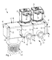
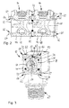
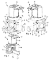
- water distribution devices 10 are shown, which are provided for a domestic dishwasher or a household washing machine as a water-bearing machine and each include a water supply module 12 and two or more water drainage modules 14 and associated cover 16. With the modules 12 and 14 and the lids 16, a modular structure of the water distribution devices 12 is created by means of which you can meet the smallest possible space nevertheless diverse requirements for water distribution even with different types of water-bearing machines.
- the water inlet module 12 is designed with a cubic inlet housing 18 made of injection-molded plastic, from the underside of which a tubular inlet connection or inlet connection 20 protrudes. At this is a dashed lines shown supply line 22 (see Fig. 1 ) connected.
- a filter 24 and a backflow preventer 26 are successively viewed.
- a flow meter 28 which is designed with a tubular turbine housing 30.
- the turbine housing 30 there are a plurality of through-openings 32 through which incoming water can pass into the interior of the turbine housing, in which then a turbine wheel 34 rotates.
- a sensor 36 see Fig.
- the flowmeter 28 is designed such that only the flow of water to a right outlet side 40 of the inlet housing 18 is measured by him, but not the flow of water to a left outlet side 42 of the inlet housing 18 (see Fig. 4 ).
- the left outlet side 42 is instead closed here by means of a lid 16.
- a further water drain module 14 can also be arranged on this outlet side 42.
- first coupling surface 44 which has a substantially square shape with respect to its outer contour.
- This first coupling surface 44 serves for coupling a water drainage module 14 or a lid 16 to the water supply module 12.
- the water drainage modules 14 are each designed with a likewise cubic drain housing 46 made of injection-molded plastic, wherein projecting from this drain housing 46 toward the front a tubular or nozzle-shaped drain port 48 protrudes. At this drain port 48 can each have a drain line 50 shown only in dashed lines (see Fig. 1 ), which then the over the Water distribution device 10 distributed water in the associated, water-bearing machine passes.
- the drain housing 46 is designed on one of its sides with a second coupling surface 52, by means of which it can be coupled in a fluid-tight manner to the first coupling surface 44 of the water supply module 12.
- the second coupling surface 52 is designed substantially square.
- a highly simplified illustrated valve 54 (see Fig. 7 ) which can be actuated by means of a valve drive 56 located outside on the outlet housing 46.
- the valve drive 56 has for this purpose an electrical valve connection 58.
- the second coupling surface 52 forms an inlet side for the water drainage module 14, through which water can flow from the water inlet module 12, in order then to be discharged from the valve 54 to the drainage port 48 in a regulated manner.
- first coupling surface 44 which is structurally identical to the first coupling surface 44 of the water supply module 12 and on the corresponding another water drain module 14 or a lid 16 can be attached.
- This further first coupling surface 44 thus forms an outlet side for the water drainage module 14 through which either water can be directed to a further water drainage module 14, in order then to be discharged there in a regulated manner or to be forwarded again.
- the coupling surfaces 44 and 52 are each designed substantially square and thus have four corners. At the first coupling surfaces 44 is located at each of these corners, a "female" junction 60, which is formed with two jaws 62 arranged in a jaw. In this mouth-shaped pin 62 then projects from the associated second coupling surface 52, a plug-in pin 64, which is associated with a local "male” junction 66.
- each pipe socket 68 is provided on the coupling surface 44, which engages an associated pipe flange 70 on the coupling surface 52.
- a further elastic seal not shown, is provided which can be arranged either on the pipe socket 68 and / or on the pipe flange 70.
- a screw 72 is provided in each case, which is screwed from the outside transversely through the pins 62 and the insertion pin 64.
- the stationary connection may be provided by a pressed-in pin, e.g. a rivet, done.
- two axially identically aligned pins can be replaced by a continuous pin.
- elements or parts of a bayonet may be formed at the corners, whereby the modules can be connected to each other by means of simple twisting.
- the cover 16 arranged on the water inlet module 12 and the respectively last water drain module 14 are likewise designed with a second coupling surface 52 with associated male connection points 66 in the form of insertion pins 64.
- water drain module 14 is provided on two sides of its drain housing 46, each with a first coupling surface 44.
- This multi-sided water drainage module 14 can be used at any position. At this water drainage module 14, two further water drainage modules 14 can be coupled accordingly, as it is in the FIGS. 11 and 12 is shown. Alternatively, only one water drainage module 14 can be coupled, but then offset at an angle of 90 ° to the water inlet module 12 and the water drainage module 14 coupled thereto.
- the drain port 48 of this multi-page Water drain module 14 is discharged downward, even three first coupling surfaces 44 may be formed on the remaining free side surfaces of the drain housing 46.
Landscapes
- Engineering & Computer Science (AREA)
- Textile Engineering (AREA)
- Water Supply & Treatment (AREA)
- Washing And Drying Of Tableware (AREA)
Applications Claiming Priority (1)
| Application Number | Priority Date | Filing Date | Title |
|---|---|---|---|
| DE102014114062.1A DE102014114062B4 (de) | 2014-09-29 | 2014-09-29 | Wasserverteileinrichtung für eine Spülmaschine oder eine Waschmaschine |
Publications (1)
| Publication Number | Publication Date |
|---|---|
| EP3000926A1 true EP3000926A1 (fr) | 2016-03-30 |
Family
ID=54147024
Family Applications (1)
| Application Number | Title | Priority Date | Filing Date |
|---|---|---|---|
| EP15185149.0A Withdrawn EP3000926A1 (fr) | 2014-09-29 | 2015-09-15 | Dispositif de distribution d'eau pour un lave-vaisselles ou un lave-linge |
Country Status (2)
| Country | Link |
|---|---|
| EP (1) | EP3000926A1 (fr) |
| DE (1) | DE102014114062B4 (fr) |
Cited By (3)
| Publication number | Priority date | Publication date | Assignee | Title |
|---|---|---|---|---|
| CN110495834A (zh) * | 2018-05-17 | 2019-11-26 | 青岛海尔洗碗机有限公司 | 一种洗碗机分水装置、洗碗机及其控制方法 |
| US10781549B2 (en) | 2019-01-31 | 2020-09-22 | Whirlpool Corporation | Dual drain system with Y-hose |
| US11053628B2 (en) | 2017-07-07 | 2021-07-06 | Whirlpool Corporation | Water supply circuit for a laundry treating appliance |
Citations (3)
| Publication number | Priority date | Publication date | Assignee | Title |
|---|---|---|---|---|
| US5172713A (en) * | 1992-04-06 | 1992-12-22 | Eaton Corporation | Modular mixing valve |
| US5313985A (en) * | 1992-08-31 | 1994-05-24 | Eaton Corporation | Modular valve assembly |
| DE102005003698A1 (de) * | 2005-01-26 | 2006-07-27 | BSH Bosch und Siemens Hausgeräte GmbH | Ventilgesteuerte Zulaufvorrichtung für wasserführende Haushaltgeräte |
Family Cites Families (2)
| Publication number | Priority date | Publication date | Assignee | Title |
|---|---|---|---|---|
| DE202005019491U1 (de) * | 2005-01-26 | 2006-02-23 | BSH Bosch und Siemens Hausgeräte GmbH | Ventilgesteuerte Zulaufvorrichtung für wasserführende Haushaltgeräte |
| DE102009052843A1 (de) * | 2009-11-13 | 2011-06-01 | Simmoteit, Robert, Dr. | Verteilerblock und Aufbereitungsvorrichtung |
-
2014
- 2014-09-29 DE DE102014114062.1A patent/DE102014114062B4/de not_active Expired - Fee Related
-
2015
- 2015-09-15 EP EP15185149.0A patent/EP3000926A1/fr not_active Withdrawn
Patent Citations (3)
| Publication number | Priority date | Publication date | Assignee | Title |
|---|---|---|---|---|
| US5172713A (en) * | 1992-04-06 | 1992-12-22 | Eaton Corporation | Modular mixing valve |
| US5313985A (en) * | 1992-08-31 | 1994-05-24 | Eaton Corporation | Modular valve assembly |
| DE102005003698A1 (de) * | 2005-01-26 | 2006-07-27 | BSH Bosch und Siemens Hausgeräte GmbH | Ventilgesteuerte Zulaufvorrichtung für wasserführende Haushaltgeräte |
Cited By (5)
| Publication number | Priority date | Publication date | Assignee | Title |
|---|---|---|---|---|
| US11053628B2 (en) | 2017-07-07 | 2021-07-06 | Whirlpool Corporation | Water supply circuit for a laundry treating appliance |
| CN110495834A (zh) * | 2018-05-17 | 2019-11-26 | 青岛海尔洗碗机有限公司 | 一种洗碗机分水装置、洗碗机及其控制方法 |
| CN110495834B (zh) * | 2018-05-17 | 2022-10-04 | 青岛海尔洗碗机有限公司 | 一种洗碗机分水装置、洗碗机及其控制方法 |
| US10781549B2 (en) | 2019-01-31 | 2020-09-22 | Whirlpool Corporation | Dual drain system with Y-hose |
| US11814768B2 (en) | 2019-01-31 | 2023-11-14 | Whirlpool Corporation | Dual drain system with Y-hose |
Also Published As
| Publication number | Publication date |
|---|---|
| DE102014114062A1 (de) | 2016-03-31 |
| DE102014114062B4 (de) | 2016-04-21 |
Similar Documents
| Publication | Publication Date | Title |
|---|---|---|
| EP2783142B1 (fr) | Dispositif permettant un raccordement sélectionnable | |
| EP2692954B1 (fr) | Armature de sortie à plusieurs flux avec sortie pivotante | |
| DE102011122921A1 (de) | Vorrichtung und Verfahren zum schaltbaren Verbinden | |
| EP2217128A1 (fr) | Appareil ménager à circulation d''eau, doté d'un répartiteur d'eau | |
| EP2287383B1 (fr) | Appareil ménager transportant de l'eau | |
| EP2217125A1 (fr) | Appareil menager a circulation d'eau equipe d'un raccordement d'eau | |
| DE112015002523T5 (de) | Modulare Verteilerleitung für einen Wasserdurchlauferhitzer | |
| EP3041984A1 (fr) | Distribution d'un liquide dans un appareil ménager | |
| DE102014114062B4 (de) | Wasserverteileinrichtung für eine Spülmaschine oder eine Waschmaschine | |
| DE202010003667U1 (de) | Ventilbaugruppe | |
| EP1431466A2 (fr) | Ensemble compact de tuyauteries et robinetteries d'alimentation en eau froide et/ou en eau de chauffage et/ou en eau potable chaude | |
| DE202012009075U1 (de) | Mehrwegeventil in einer Vorrichtung zur Milchschaumbereitung | |
| EP2489951B1 (fr) | Chauffe-eau instantané électrique | |
| DE202005019491U1 (de) | Ventilgesteuerte Zulaufvorrichtung für wasserführende Haushaltgeräte | |
| DE2850084C2 (de) | Wandeinbau-Ablaufarmatur mit Geruchsverschluß | |
| DE102009031044B4 (de) | Anschluss einer sekundären Leitung einer Reinwasser-Hauptversorgungsleitung an ein Dialysegerät oder dergleichen | |
| EP3012553B1 (fr) | Composant pour une installation de chauffage | |
| DE3433871C2 (fr) | ||
| DE4326352C2 (de) | Fluid-Kanalvorrichtung für Haushaltgeräte | |
| CH676492A5 (fr) | ||
| DE102016111102A1 (de) | Wassereinlauf eines wasserführenden Haushaltsgeräts | |
| EP1039042B1 (fr) | Raccord pour compteur d'eau à un boítier pour conduite d'eau | |
| DE19813946C1 (de) | Röhrenheizkörper | |
| DE102007005851B4 (de) | Handbrause | |
| DE20118332U1 (de) | Düse für Whirlpoolwannen |
Legal Events
| Date | Code | Title | Description |
|---|---|---|---|
| PUAI | Public reference made under article 153(3) epc to a published international application that has entered the european phase |
Free format text: ORIGINAL CODE: 0009012 |
|
| AK | Designated contracting states |
Kind code of ref document: A1 Designated state(s): AL AT BE BG CH CY CZ DE DK EE ES FI FR GB GR HR HU IE IS IT LI LT LU LV MC MK MT NL NO PL PT RO RS SE SI SK SM TR |
|
| AX | Request for extension of the european patent |
Extension state: BA ME |
|
| 17P | Request for examination filed |
Effective date: 20160225 |
|
| RBV | Designated contracting states (corrected) |
Designated state(s): AL AT BE BG CH CY CZ DE DK EE ES FI FR GB GR HR HU IE IS IT LI LT LU LV MC MK MT NL NO PL PT RO RS SE SI SK SM TR |
|
| STAA | Information on the status of an ep patent application or granted ep patent |
Free format text: STATUS: THE APPLICATION IS DEEMED TO BE WITHDRAWN |
|
| 18D | Application deemed to be withdrawn |
Effective date: 20200603 |