EP3000954B1 - Cylindre électronique à structure étanche - Google Patents
Cylindre électronique à structure étanche Download PDFInfo
- Publication number
- EP3000954B1 EP3000954B1 EP14186755.6A EP14186755A EP3000954B1 EP 3000954 B1 EP3000954 B1 EP 3000954B1 EP 14186755 A EP14186755 A EP 14186755A EP 3000954 B1 EP3000954 B1 EP 3000954B1
- Authority
- EP
- European Patent Office
- Prior art keywords
- exterior
- motor
- recess
- waterproof
- electronic cylinder
- Prior art date
- Legal status (The legal status is an assumption and is not a legal conclusion. Google has not performed a legal analysis and makes no representation as to the accuracy of the status listed.)
- Active
Links
Images




Classifications
-
- E—FIXED CONSTRUCTIONS
- E05—LOCKS; KEYS; WINDOW OR DOOR FITTINGS; SAFES
- E05B—LOCKS; ACCESSORIES THEREFOR; HANDCUFFS
- E05B47/00—Operating or controlling locks or other fastening devices by electric or magnetic means
- E05B47/06—Controlling mechanically-operated bolts by electro-magnetically-operated detents
- E05B47/0611—Cylinder locks with electromagnetic control
- E05B47/0638—Cylinder locks with electromagnetic control by disconnecting the rotor
- E05B47/0642—Cylinder locks with electromagnetic control by disconnecting the rotor axially, i.e. with an axially disengaging coupling element
-
- E—FIXED CONSTRUCTIONS
- E05—LOCKS; KEYS; WINDOW OR DOOR FITTINGS; SAFES
- E05B—LOCKS; ACCESSORIES THEREFOR; HANDCUFFS
- E05B17/00—Accessories in connection with locks
- E05B17/002—Weather or dirt protection
-
- E—FIXED CONSTRUCTIONS
- E05—LOCKS; KEYS; WINDOW OR DOOR FITTINGS; SAFES
- E05B—LOCKS; ACCESSORIES THEREFOR; HANDCUFFS
- E05B47/00—Operating or controlling locks or other fastening devices by electric or magnetic means
- E05B47/06—Controlling mechanically-operated bolts by electro-magnetically-operated detents
- E05B47/0611—Cylinder locks with electromagnetic control
- E05B47/0615—Cylinder locks with electromagnetic control operated by handles, e.g. by knobs
-
- E—FIXED CONSTRUCTIONS
- E05—LOCKS; KEYS; WINDOW OR DOOR FITTINGS; SAFES
- E05B—LOCKS; ACCESSORIES THEREFOR; HANDCUFFS
- E05B47/00—Operating or controlling locks or other fastening devices by electric or magnetic means
- E05B47/0001—Operating or controlling locks or other fastening devices by electric or magnetic means with electric actuators; Constructional features thereof
- E05B47/0012—Operating or controlling locks or other fastening devices by electric or magnetic means with electric actuators; Constructional features thereof with rotary electromotors
Definitions
- the present invention relates generally to an electronic cylinder and more particularly to an electronic cylinder having waterproof structure between a motor and other component so as to provide waterproof effect.
- the primary object of using an electronic lock is to prevent theft.
- the electronic lock itself should possess durable wearing or corrosion, lesser damage and malfunction are some major factors what the consumers consider generally when purchasing or selecting the electronic locks.
- the lesser malfunction of electronic lock depends on materials from which the components are fabricated, such as aging and fatigue of plastic substances, service life of electronic elements, motor durability, waterproof, fire-proof and moisture-proof of battery or circuit design play important role and affect the usage span of the electronic lock. In case the electronic lock one uses malfunctions often and hence cannot provide safety measures to his belongings, which in turn may hinder the user to go out safely or enter his house conveniently.
- the motor disposed within electronic cylinder for activating a latch assembly so as to lock and unlock a door is the most important element in an electronic lock.
- Presently available electronic cylinders in the markets are not provided with anti-moisture or waterproof effects. Taiwan being located in sub-tropical area (rainy and humid environment), moisture can easily penetrate through the lock heart or other parts via gaps connecting the components.
- Taiwan being located in sub-tropical area (rainy and humid environment), moisture can easily penetrate through the lock heart or other parts via gaps connecting the components.
- the electronic lock is usually provided on the external door, which adds moisture as rain or splashing water infiltration, resulting in malfunction of internal components in the electronic lock. Therefore, it is highly desired to find a way to protect the invasion of moisture into the motor while strengthening the structure of waterproof function in other parts to enhance waterproof effects of the electronic cylinder, thereby decreasing malfunction of the electronic lock.
- a primary objective of the present invention is to provide an electronic lock, simply an electronic cylinder including a motor which has filled by waterproof filler so as to provide a waterproof structure thereto, so as to permit traditional performance in a way while preventing malfunction of the motor in the other way.
- Another objective of the present invention is to provide an electronic cylinder with enhanced waterproof structure such that waterproof ring and waterproof washers are provided at gaps existing among the elements so as to prevent invasion of water, thereby causing the electronic cylinder of the present invention to possess waterproof effects.
- An electronic cylinder of the present invention accordingly includes an exterior knob; an exterior cylinder core connected securely to an end of the exterior knob; a motor disposed within the exterior cylinder core, having a protrusion block and an axle extending axially and outwardly from the protrusion block; a clutch unit connected operably to the motor; a cam member associated with the clutch unit and the motor for driving a latch assembly to lock or unlock the door upon causing rotation between the clutch unit and the motor; a cylindrical coupler seat disposed between the motor and the clutch unit, including a rear chamber for receiving the clutch unit and a front portion located opposite to the rear chamber and having a front end face provided with a blocking opening constituted by an injection channel indented inwardly from the front end face and extending inwardly and radially from a first point of a periphery confining the front end face, an recess indented inwardly and axially from a bottom surface of the injection channel and an outflow channel indented inwardly from the front end face and extending in
- the protrusion block of the motor is generally cylindrical.
- the recess has a shape complementing with the protrusion block.
- the preventing block 513 is generally semi-circular in shape.
- the waterproof filler is selected from a group consisting of Polydimethylsiloxane (PDMS).
- PDMS Polydimethylsiloxane
- the exterior cylinder core defines an interior chamber for receiving the motor.
- the electronic cylinder of the present invention further includes a waterproof ring sleeved around an outer surface of the cylindrical coupler seat so as to abut hermetically against the interior chamber, thereby providing an additional waterproof effect among the motor, the cylindrical coupler seat and the exterior cylinder core.
- the electronic cylinder of the present invention further includes a first waterproof washer sandwiched between the exterior cylinder core and the exterior knob in order to provide additional waterproof effect therebetween.
- the exterior knob includes an exterior housing and an interior housing that is located inside the exterior housing and that defines the end of the exterior knob for connected securely to the exterior cylinder core.
- the electronic cylinder of the present invention further includes a second waterproof washer disposed between the exterior and interior housings.
- the motor located with the coupler seat is waterproof, thereby preventing damage done onto it.
- the waterproof ring and waterproof washers are disposed among the gaps connecting elements relative to one another, water is prevented from getting into the interior of the electronic cylinder of the present invention, thereby prolonging the service life of the present electronic cylinder.
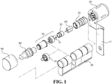
- Fig. 1 is an exploded view of an electronic cylinder of the present invention having waterproof structure.
- the electronic cylinder of the present invention for a door includes an exterior knob 10, an exterior cylinder core 20, a lock housing 30, a motor 40, a clutch unit 60, a cam member 70 and a sensing device (not visible).
- the exterior knob 10 is generally installed on a front side of the door (not visible), which is provided with a handle 14.
- the exterior cylinder core 20 is disposed on a rear side of the door and is connected securely to an end of the exterior knob 10.
- the motor 40 is disposed within the exterior cylinder core 20.
- the clutch unit 60 is connected operably to the motor 40.
- the assembly of the clutch unit 60 and the motor 40 is disposed within the lock housing 30, which in turn is installed on the rear side of the door.
- the cam member 70 is associated with the clutch unit 60 and the motor 40 for driving a latch assembly which is generally connected with the lock housing 30 to lock or unlock the door with respect to the door frame (not visible) upon causing rotation between the clutch unit 60 and the motor 40.
- the cam member 70 can include a transmission rod, oval-shaped paddle or any other mechanism operably connected to the latch assembly so long it can drive the lock mechanism to open and close the door.
- the electronic cylinder of the present invention further includes an interior knob 90 which is generally installed on the rear side of the door (not visible) and an interior cylinder core 80 interconnecting the interior knob 90 and the clutch unit 60 in a known manner.
- a cylindrical coupler seat 50 is disposed between the motor 40 and the clutch unit 60, includes a rear chamber 501 for receiving movably an extension portion 61 of the clutch unit 60.
- the motor 40 has an annular protrusion block 42 and an axle 41 extending axially and outwardly from the protrusion block 42.
- the structure of the motor 40 should not be limited only the disclosed ones, any driving means can be employed so long as it can engage with the extension portion 61 of the clutch unit 60 so as to cause rotation therebetween.
- the coupler seat 50 has a front portion that located opposite to the rear chamber 501 and that has a front end face provided with a blocking opening 51 constituted by an injection channel 511 indented inwardly from the front end face and extending inwardly and radially from a first point of a periphery confining the front end face, an annular recess 512 indented inwardly and axially from a bottom surface of the injection channel 511 and an outflow channel 514 indented inwardly from the front end face and extending inwardly and radially from a second point of the periphery opposite to the first point to terminate at the recess 512.
- the bottom surface of the recess 512 is formed with a through hole 52 via which the axle 41 extends for operably engaging the extension portion 61 of the clutch unit 60.
- the front portion further has a preventing block 513 formed between the bottom surface of the recess 512 and the outflow channel 514.
- the preventing block 513 is located in a depth with respect to the front end face complementing with the protrusion block 42 of the motor 40 such that once the protrusion block 42 is seated in the recess 512, the front end face of the coupler seat 50 abuts fittingly and sealingly against the motor 40 around the protrusion block 42, thereby forming a communication passage between the coupler seat 50 and the motor 40 constituted by the above mentioned channels and recess.
- the preventing block 513 is generally semi-circular in shape.
- the structure of the preventing block 513 should not be limited only to the disclosed ones, any other structure like cylinder or rectangular can be used so long it can achieve the desired purpose.
- Fig. 2 is a perspective view of the clutch unit 60, the cylindrical coupler seat 50, the motor 40 and the exterior cylinder core 20 cooperatively constituting the electronic cylinder of the present invention
- Fig. 3 is an enlarged view of the cylindrical coupler seat 50 and the motor 40 shown in Fig. 2
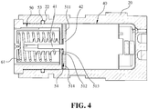
- Fig. 4 is a cross-sectional view of assembled elements shown in Fig. 2 .
- the blocking opening 51 defines the communication passage between the coupler seat 50 and the motor 40 constituted by the above mentioned channels and recess.
- a waterproof filler 54 is injected from the injection channel 511 so as to hermetically filling the recess 512 in the coupler seat 50 upon encountering the preventing block 513 and simultaneously filling the ambient space around the axle 41 follow by and the outflow channel 514.
- the entire portion surrounding the protrusion block 42 is replete with the waterproof filler 54 such that in case of invasion of water via the clutch unit 60 and the cam member 70, water cannot penetrate into the motor 40, thereby providing waterproof effect to the motor 40.
- the waterproof filler 54 is selected from a group consisting of Polydimethylsiloxane (PDMS). Any other filler, such as silicone oil and Vaseline, can be used so long they can provide hermetical sealing effect to the motor 40.
- PDMS Polydimethylsiloxane
- Fig. 4 is a cross-sectional view of assembled elements shown in Fig. 2 .
- the exterior cylinder core 20 defines an interior chamber for receiving the motor 40.
- the electronic cylinder of the present invention further includes a waterproof ring 53 sleeved around an outer surface of the cylindrical coupler seat 50 so as to abut hermetically against an annular recess 22 formed in the interior chamber, so that water cannot invade into the gaps formed among the clutch unit 60, the cylindrical coupler seat 50 and the exterior cylinder core 20, thereby providing an additional waterproof effect among the clutch unit 60, the cylindrical coupler seat 50 and the exterior cylinder core 20.
- Fig. 5 shows how a first waterproof washer is sandwiched between the exterior cylinder core 20 and the exterior knob 10 shown in Fig. 1 in order to provide additional waterproof effect in the electronic cylinder of the present invention.
- the electronic cylinder of the present invention further includes a first waterproof washer 21 sandwiched between the exterior cylinder core and the exterior knob 10 in order to provide additional waterproof effect therebetween.
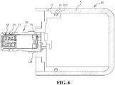
- Fig. 6 is a cross-sectional view illustrating how a second waterproof washer is provided between the exterior cylinder core 20 and in the exterior knob 10 shown in Fig. 1 in order to provide additional waterproof effect in the electronic cylinder of the present invention
- Fig.7 shows an exploded and enlarged view of the exterior knob 10 employed in the electronic cylinder of the present invention.
- the electronic cylinder of the present invention further includes a waterproof washer 21 sandwiched between the exterior cylinder core 20 and the exterior knob 10 in order to provide additional waterproof effect to a chamber 121 formed in the rear side of the exterior knob 10.
- the exterior knob 10 includes an exterior housing 11 and an interior housing 12 that is located inside the exterior housing 11 and that defines the end of the exterior knob 10 for connected securely to the exterior cylinder core 20.
- the electronic cylinder of the present invention includes a waterproof ring 13 disposed in an annular recess 122 formed on an outer surface of the interior housing 12 so as to abut sealingly against the inner surface of the interior housing 11, thereby providing an additional waterproof effect to the exterior knob 10.
- One distinct feature of the present invention resides in that injection of the waterproof filler 54 is finished swiftly due to the following reasons.
- the injection channel 511 and the outflow channel 514 are aligned with each other, and have the same depth with respect to the front end face but a different width relative to each other, wherein the injection channel 511 has a larger width than the outflow channel 514 to facilitate injection of the waterproof filler 54 filling the blocking opening 51.
Landscapes
- Physics & Mathematics (AREA)
- Electromagnetism (AREA)
- Lock And Its Accessories (AREA)
Claims (9)
- Un cylindre électronique pour une serrure de porte comprenant :un bouton extérieur (10);un noyau de cylindre extérieur (20) raccordé solidement à une extrémité dudit bouton extérieur (10);un moteur (40) disposé à l'intérieur dudit noyau de cylindre extérieur (20), ayant un bloc faisant saillie (42) et un axe (41) s'étendant axialement et vers l'extérieur à partir dudit bloc faisant saillie (42);une unité d'embrayage (60) raccordée fonctionnellement audit moteur (40) ;un élément de came (70) associé à ladite unité d'embrayage (60) et ledit moteur (40) étant destiné à entraîner un ensemble de verrouillage pour qu'il verrouille ou déverrouille la porte lorsqu'une rotation est provoquée entre ladite unité d'embrayage (60) et ledit moteur (40);un siège de couplage cylindrique (50) disposé entre ledit moteur (40) et ladite unité d'embrayage (60),caractérisé en ce quele siège de couplage cylindrique (50) inclut une chambre arrière (501) destinée à recevoir ladite unité d'embrayage (60) et une portion avant située à l'opposé de ladite chambre arrière (501) et ayant une face d'extrémité avant pourvue d'une ouverture de blocage (51) constituée d'un canal d'injection (511) renfoncé vers l'intérieur à partir de ladite face d'extrémité avant et s'étendant vers l'intérieur et radialement à partir d'un premier point d'une périphérie délimitant ladite face d'extrémité avant, un évidement (512) renfoncé vers l'intérieur et axialement à partir d'une surface de dessous dudit canal d'injection (511) et un canal de sortie (514) renfoncé vers l'intérieur à partir de ladite face d'extrémité avant et s'étendant vers l'intérieur et radialement à partir d'un deuxième point de la périphérie opposée audit premier point pour se terminer au niveau dudit évidement (512), ladite surface de dessous dudit évidement (512) étant formée avec un trou traversant (52) permettant l'extension dudit axe (41) pour une mise en prise fonctionnelle avec ladite unité d'embrayage (60), ladite portion avant ayant en outre un bloc de retenue (513) formé entre ladite surface de dessous dudit évidement (512) et ledit canal de sortie (514), ledit bloc de retenue (513) étant situé dans une profondeur par rapport à ladite face d'extrémité avant de façon complémentaire audit bloc faisant saillie (42) dudit moteur (40) de telle sorte qu'une fois que ledit bloc faisant saillie (42) est logé dans ledit évidement (512), ladite face d'extrémité avant dudit siège de couplage (50) bute en ajustement serré contre ledit moteur (40) autour dudit bloc faisant saillie (42) ; et dans le fait de comprendre une garniture de remplissage étanche (54) remplissant de façon hermétique ledit évidement (512) dans ledit siège de couplage (50).
- Le cylindre électronique selon la revendication 1, où ledit bloc faisant saillie (42) dudit moteur (40) est généralement cylindrique, ledit évidement (512) ayant une forme complémentaire audit bloc faisant saillie (42).
- Le cylindre électronique selon la revendication 2, où ledit bloc de retenue (513) est de forme généralement semi-circulaire.
- Le cylindre électronique selon la revendication 1, où ledit bloc de retenue (513) est de forme généralement semi-circulaire.
- Le cylindre électronique selon la revendication 1, où ladite garniture de remplissage étanche est sélectionnée dans un groupe composé du polydiméthylsiloxane (PDMS).
- Le cylindre électronique selon la revendication 1, où ledit noyau de cylindre extérieur (20) définit une chambre intérieure (121) destinée à recevoir ledit moteur (40), le cylindre électronique comprenant en outre une bague étanche (13, 53) manchonnée autour d'une surface externe dudit siège de couplage cylindrique (50) de manière à buter hermétiquement contre ladite chambre intérieure (121) dans ledit noyau de cylindre extérieur (20), fournissant ainsi un effet d'étanchéité supplémentaire dans ladite unité d'embrayage (60), ledit siège de couplage cylindrique (50) et ledit noyau de cylindre extérieur (20).
- Le cylindre électronique selon la revendication 1, comprenant en outre une rondelle étanche (21) prise en sandwich entre ledit noyau de cylindre extérieur (20) et ledit bouton extérieur (10) afin de fournir un effet d'étanchéité supplémentaire entre ceux-ci.
- Le cylindre électronique selon la revendication 1, où ledit bouton extérieur (10) inclut un logement extérieur (11) et un logement intérieur (11, 12) qui est situé à l'intérieur dudit logement extérieur (11) et qui définit ladite extrémité dudit bouton extérieur (10) pour un raccord solide audit noyau de cylindre extérieur (20), ledit cylindre électronique comprenant en outre une bague étanche (13, 53) disposée entre lesdits logements extérieur et intérieur.
- Le cylindre électronique selon la revendication 1, où ledit canal d'injection (511) et ledit canal de sortie (514) sont alignés l'un avec l'autre, et ont la même profondeur par rapport à ladite face d'extrémité avant mais une largeur différente l'un relativement à l'autre, où ledit canal d'injection (511) a une largeur plus grande et une profondeur plus profonde que ledit canal de sortie (514) pour faciliter l'injection de ladite garniture de remplissage étanche (54) remplissant ledit évidement (512).
Priority Applications (1)
| Application Number | Priority Date | Filing Date | Title |
|---|---|---|---|
| EP14186755.6A EP3000954B1 (fr) | 2014-09-29 | 2014-09-29 | Cylindre électronique à structure étanche |
Applications Claiming Priority (1)
| Application Number | Priority Date | Filing Date | Title |
|---|---|---|---|
| EP14186755.6A EP3000954B1 (fr) | 2014-09-29 | 2014-09-29 | Cylindre électronique à structure étanche |
Publications (2)
| Publication Number | Publication Date |
|---|---|
| EP3000954A1 EP3000954A1 (fr) | 2016-03-30 |
| EP3000954B1 true EP3000954B1 (fr) | 2017-04-26 |
Family
ID=51661889
Family Applications (1)
| Application Number | Title | Priority Date | Filing Date |
|---|---|---|---|
| EP14186755.6A Active EP3000954B1 (fr) | 2014-09-29 | 2014-09-29 | Cylindre électronique à structure étanche |
Country Status (1)
| Country | Link |
|---|---|
| EP (1) | EP3000954B1 (fr) |
Cited By (1)
| Publication number | Priority date | Publication date | Assignee | Title |
|---|---|---|---|---|
| CN106088829A (zh) * | 2016-08-02 | 2016-11-09 | 江苏雷利电机股份有限公司 | 门锁驱动装置和应用其的电控门锁 |
Families Citing this family (2)
| Publication number | Priority date | Publication date | Assignee | Title |
|---|---|---|---|---|
| CN112197001B (zh) * | 2020-08-25 | 2022-08-02 | 中国空气动力研究与发展中心低速空气动力研究所 | 一种电动缸在低温低压高湿度环境下的防护方法 |
| EP4092228B1 (fr) * | 2021-05-18 | 2023-08-30 | SimonsVoss Technologies GmbH | Cylindre électronique de fermeture pourvu d'actionneur étanche |
Family Cites Families (3)
| Publication number | Priority date | Publication date | Assignee | Title |
|---|---|---|---|---|
| DE602005022046D1 (de) * | 2005-03-30 | 2010-08-12 | Wfe Technology Corp | Zylinderschlosseinheit mit mechanischem und elektronischem Mechanismus |
| ES2331864B1 (es) * | 2008-07-15 | 2010-10-28 | Salto Systems, S.L. | Cilindro electromecanico para cerradura. |
| TWI458882B (zh) * | 2012-05-15 | 2014-11-01 | Wfe Technology Corp | 電子鎖之作動馬達組 |
-
2014
- 2014-09-29 EP EP14186755.6A patent/EP3000954B1/fr active Active
Non-Patent Citations (1)
| Title |
|---|
| None * |
Cited By (1)
| Publication number | Priority date | Publication date | Assignee | Title |
|---|---|---|---|---|
| CN106088829A (zh) * | 2016-08-02 | 2016-11-09 | 江苏雷利电机股份有限公司 | 门锁驱动装置和应用其的电控门锁 |
Also Published As
| Publication number | Publication date |
|---|---|
| EP3000954A1 (fr) | 2016-03-30 |
Similar Documents
| Publication | Publication Date | Title |
|---|---|---|
| US9577487B2 (en) | Electronic cylinder with waterproof structure | |
| KR102371331B1 (ko) | 내수성 터치 키패드를 가지는 잠금장치 | |
| EP3000954B1 (fr) | Cylindre électronique à structure étanche | |
| US7300190B2 (en) | Vehicle door handle device | |
| US6852929B2 (en) | Elastomer seal and housing for a remote keyless entry device | |
| EP2749718B1 (fr) | Dispositif de poignée externe pour portière de véhicule | |
| US20100088856A1 (en) | External handle on doors or hatches of vehicle | |
| EP1881567B1 (fr) | Structure isolante entre des éléments conducteurs d'un dispositif électrique | |
| US20130200768A1 (en) | Waterproof structure for electronic device | |
| US20150214991A1 (en) | Housing for Portable Electronic Device | |
| WO2008069823A3 (fr) | Coffre-fort avec porte à cartouche de verrouillage | |
| CN101622411B (zh) | 门拉手装置 | |
| JP5653321B2 (ja) | 保護カバーおよびそれを備える電子機器 | |
| WO2005080152A3 (fr) | Module de verrouillage de direction | |
| US20070054521A1 (en) | Dust-proof cover for network jack | |
| KR101279872B1 (ko) | 디지털 도어록 보호 커버 | |
| EP1847970A2 (fr) | Boîtier, en particulier pour une clé électronique | |
| KR20150102762A (ko) | 차량의 로고 일체형 트렁크 스위치 어셈블리 | |
| EP2886760A1 (fr) | Boîtier de dispositif électronique destiné à être placé au sein d'une poignée de porte de véhicule automobile, dispositif électronique correspondant et poignée de porte correspondante | |
| TW201604365A (zh) | 電子鎖之防水結構 | |
| KR200188617Y1 (ko) | 자물쇠 보호케이스 | |
| JP4986705B2 (ja) | シリンダ錠の防水構造 | |
| US20060227031A1 (en) | Remote control device protector | |
| KR101988618B1 (ko) | 전자장치 보호를 위한 방호함 | |
| KR20160145979A (ko) | 디지털 도어락 보호커버의 변형 |
Legal Events
| Date | Code | Title | Description |
|---|---|---|---|
| PUAI | Public reference made under article 153(3) epc to a published international application that has entered the european phase |
Free format text: ORIGINAL CODE: 0009012 |
|
| AK | Designated contracting states |
Kind code of ref document: A1 Designated state(s): AL AT BE BG CH CY CZ DE DK EE ES FI FR GB GR HR HU IE IS IT LI LT LU LV MC MK MT NL NO PL PT RO RS SE SI SK SM TR |
|
| AX | Request for extension of the european patent |
Extension state: BA ME |
|
| 17P | Request for examination filed |
Effective date: 20160428 |
|
| RBV | Designated contracting states (corrected) |
Designated state(s): AL AT BE BG CH CY CZ DE DK EE ES FI FR GB GR HR HU IE IS IT LI LT LU LV MC MK MT NL NO PL PT RO RS SE SI SK SM TR |
|
| GRAP | Despatch of communication of intention to grant a patent |
Free format text: ORIGINAL CODE: EPIDOSNIGR1 |
|
| INTG | Intention to grant announced |
Effective date: 20161214 |
|
| GRAS | Grant fee paid |
Free format text: ORIGINAL CODE: EPIDOSNIGR3 |
|
| GRAA | (expected) grant |
Free format text: ORIGINAL CODE: 0009210 |
|
| AK | Designated contracting states |
Kind code of ref document: B1 Designated state(s): AL AT BE BG CH CY CZ DE DK EE ES FI FR GB GR HR HU IE IS IT LI LT LU LV MC MK MT NL NO PL PT RO RS SE SI SK SM TR |
|
| REG | Reference to a national code |
Ref country code: GB Ref legal event code: FG4D |
|
| REG | Reference to a national code |
Ref country code: CH Ref legal event code: EP |
|
| REG | Reference to a national code |
Ref country code: AT Ref legal event code: REF Ref document number: 888025 Country of ref document: AT Kind code of ref document: T Effective date: 20170515 |
|
| REG | Reference to a national code |
Ref country code: IE Ref legal event code: FG4D |
|
| REG | Reference to a national code |
Ref country code: DE Ref legal event code: R096 Ref document number: 602014008982 Country of ref document: DE |
|
| REG | Reference to a national code |
Ref country code: FR Ref legal event code: PLFP Year of fee payment: 4 |
|
| REG | Reference to a national code |
Ref country code: NL Ref legal event code: MP Effective date: 20170426 |
|
| REG | Reference to a national code |
Ref country code: LT Ref legal event code: MG4D |
|
| REG | Reference to a national code |
Ref country code: AT Ref legal event code: MK05 Ref document number: 888025 Country of ref document: AT Kind code of ref document: T Effective date: 20170426 |
|
| PG25 | Lapsed in a contracting state [announced via postgrant information from national office to epo] |
Ref country code: NL Free format text: LAPSE BECAUSE OF FAILURE TO SUBMIT A TRANSLATION OF THE DESCRIPTION OR TO PAY THE FEE WITHIN THE PRESCRIBED TIME-LIMIT Effective date: 20170426 |
|
| PG25 | Lapsed in a contracting state [announced via postgrant information from national office to epo] |
Ref country code: FI Free format text: LAPSE BECAUSE OF FAILURE TO SUBMIT A TRANSLATION OF THE DESCRIPTION OR TO PAY THE FEE WITHIN THE PRESCRIBED TIME-LIMIT Effective date: 20170426 Ref country code: HR Free format text: LAPSE BECAUSE OF FAILURE TO SUBMIT A TRANSLATION OF THE DESCRIPTION OR TO PAY THE FEE WITHIN THE PRESCRIBED TIME-LIMIT Effective date: 20170426 Ref country code: NO Free format text: LAPSE BECAUSE OF FAILURE TO SUBMIT A TRANSLATION OF THE DESCRIPTION OR TO PAY THE FEE WITHIN THE PRESCRIBED TIME-LIMIT Effective date: 20170726 Ref country code: ES Free format text: LAPSE BECAUSE OF FAILURE TO SUBMIT A TRANSLATION OF THE DESCRIPTION OR TO PAY THE FEE WITHIN THE PRESCRIBED TIME-LIMIT Effective date: 20170426 Ref country code: AT Free format text: LAPSE BECAUSE OF FAILURE TO SUBMIT A TRANSLATION OF THE DESCRIPTION OR TO PAY THE FEE WITHIN THE PRESCRIBED TIME-LIMIT Effective date: 20170426 Ref country code: LT Free format text: LAPSE BECAUSE OF FAILURE TO SUBMIT A TRANSLATION OF THE DESCRIPTION OR TO PAY THE FEE WITHIN THE PRESCRIBED TIME-LIMIT Effective date: 20170426 Ref country code: GR Free format text: LAPSE BECAUSE OF FAILURE TO SUBMIT A TRANSLATION OF THE DESCRIPTION OR TO PAY THE FEE WITHIN THE PRESCRIBED TIME-LIMIT Effective date: 20170727 |
|
| PG25 | Lapsed in a contracting state [announced via postgrant information from national office to epo] |
Ref country code: IS Free format text: LAPSE BECAUSE OF FAILURE TO SUBMIT A TRANSLATION OF THE DESCRIPTION OR TO PAY THE FEE WITHIN THE PRESCRIBED TIME-LIMIT Effective date: 20170826 Ref country code: LV Free format text: LAPSE BECAUSE OF FAILURE TO SUBMIT A TRANSLATION OF THE DESCRIPTION OR TO PAY THE FEE WITHIN THE PRESCRIBED TIME-LIMIT Effective date: 20170426 Ref country code: PL Free format text: LAPSE BECAUSE OF FAILURE TO SUBMIT A TRANSLATION OF THE DESCRIPTION OR TO PAY THE FEE WITHIN THE PRESCRIBED TIME-LIMIT Effective date: 20170426 Ref country code: BG Free format text: LAPSE BECAUSE OF FAILURE TO SUBMIT A TRANSLATION OF THE DESCRIPTION OR TO PAY THE FEE WITHIN THE PRESCRIBED TIME-LIMIT Effective date: 20170726 Ref country code: SE Free format text: LAPSE BECAUSE OF FAILURE TO SUBMIT A TRANSLATION OF THE DESCRIPTION OR TO PAY THE FEE WITHIN THE PRESCRIBED TIME-LIMIT Effective date: 20170426 Ref country code: RS Free format text: LAPSE BECAUSE OF FAILURE TO SUBMIT A TRANSLATION OF THE DESCRIPTION OR TO PAY THE FEE WITHIN THE PRESCRIBED TIME-LIMIT Effective date: 20170426 |
|
| REG | Reference to a national code |
Ref country code: DE Ref legal event code: R097 Ref document number: 602014008982 Country of ref document: DE |
|
| PG25 | Lapsed in a contracting state [announced via postgrant information from national office to epo] |
Ref country code: RO Free format text: LAPSE BECAUSE OF FAILURE TO SUBMIT A TRANSLATION OF THE DESCRIPTION OR TO PAY THE FEE WITHIN THE PRESCRIBED TIME-LIMIT Effective date: 20170426 Ref country code: EE Free format text: LAPSE BECAUSE OF FAILURE TO SUBMIT A TRANSLATION OF THE DESCRIPTION OR TO PAY THE FEE WITHIN THE PRESCRIBED TIME-LIMIT Effective date: 20170426 Ref country code: CZ Free format text: LAPSE BECAUSE OF FAILURE TO SUBMIT A TRANSLATION OF THE DESCRIPTION OR TO PAY THE FEE WITHIN THE PRESCRIBED TIME-LIMIT Effective date: 20170426 Ref country code: DK Free format text: LAPSE BECAUSE OF FAILURE TO SUBMIT A TRANSLATION OF THE DESCRIPTION OR TO PAY THE FEE WITHIN THE PRESCRIBED TIME-LIMIT Effective date: 20170426 Ref country code: SK Free format text: LAPSE BECAUSE OF FAILURE TO SUBMIT A TRANSLATION OF THE DESCRIPTION OR TO PAY THE FEE WITHIN THE PRESCRIBED TIME-LIMIT Effective date: 20170426 |
|
| PG25 | Lapsed in a contracting state [announced via postgrant information from national office to epo] |
Ref country code: SM Free format text: LAPSE BECAUSE OF FAILURE TO SUBMIT A TRANSLATION OF THE DESCRIPTION OR TO PAY THE FEE WITHIN THE PRESCRIBED TIME-LIMIT Effective date: 20170426 |
|
| PLBE | No opposition filed within time limit |
Free format text: ORIGINAL CODE: 0009261 |
|
| STAA | Information on the status of an ep patent application or granted ep patent |
Free format text: STATUS: NO OPPOSITION FILED WITHIN TIME LIMIT |
|
| 26N | No opposition filed |
Effective date: 20180129 |
|
| REG | Reference to a national code |
Ref country code: CH Ref legal event code: PL |
|
| PG25 | Lapsed in a contracting state [announced via postgrant information from national office to epo] |
Ref country code: SI Free format text: LAPSE BECAUSE OF FAILURE TO SUBMIT A TRANSLATION OF THE DESCRIPTION OR TO PAY THE FEE WITHIN THE PRESCRIBED TIME-LIMIT Effective date: 20170426 Ref country code: MC Free format text: LAPSE BECAUSE OF FAILURE TO SUBMIT A TRANSLATION OF THE DESCRIPTION OR TO PAY THE FEE WITHIN THE PRESCRIBED TIME-LIMIT Effective date: 20170426 |
|
| REG | Reference to a national code |
Ref country code: IE Ref legal event code: MM4A |
|
| REG | Reference to a national code |
Ref country code: BE Ref legal event code: MM Effective date: 20170930 |
|
| PG25 | Lapsed in a contracting state [announced via postgrant information from national office to epo] |
Ref country code: LU Free format text: LAPSE BECAUSE OF NON-PAYMENT OF DUE FEES Effective date: 20170929 |
|
| REG | Reference to a national code |
Ref country code: FR Ref legal event code: PLFP Year of fee payment: 5 |
|
| PG25 | Lapsed in a contracting state [announced via postgrant information from national office to epo] |
Ref country code: CH Free format text: LAPSE BECAUSE OF NON-PAYMENT OF DUE FEES Effective date: 20170930 Ref country code: LI Free format text: LAPSE BECAUSE OF NON-PAYMENT OF DUE FEES Effective date: 20170930 Ref country code: IE Free format text: LAPSE BECAUSE OF NON-PAYMENT OF DUE FEES Effective date: 20170929 |
|
| PG25 | Lapsed in a contracting state [announced via postgrant information from national office to epo] |
Ref country code: BE Free format text: LAPSE BECAUSE OF NON-PAYMENT OF DUE FEES Effective date: 20170930 |
|
| PG25 | Lapsed in a contracting state [announced via postgrant information from national office to epo] |
Ref country code: MT Free format text: LAPSE BECAUSE OF NON-PAYMENT OF DUE FEES Effective date: 20170929 |
|
| PG25 | Lapsed in a contracting state [announced via postgrant information from national office to epo] |
Ref country code: HU Free format text: LAPSE BECAUSE OF FAILURE TO SUBMIT A TRANSLATION OF THE DESCRIPTION OR TO PAY THE FEE WITHIN THE PRESCRIBED TIME-LIMIT; INVALID AB INITIO Effective date: 20140929 |
|
| PG25 | Lapsed in a contracting state [announced via postgrant information from national office to epo] |
Ref country code: CY Free format text: LAPSE BECAUSE OF FAILURE TO SUBMIT A TRANSLATION OF THE DESCRIPTION OR TO PAY THE FEE WITHIN THE PRESCRIBED TIME-LIMIT Effective date: 20170426 |
|
| PG25 | Lapsed in a contracting state [announced via postgrant information from national office to epo] |
Ref country code: MK Free format text: LAPSE BECAUSE OF FAILURE TO SUBMIT A TRANSLATION OF THE DESCRIPTION OR TO PAY THE FEE WITHIN THE PRESCRIBED TIME-LIMIT Effective date: 20170426 |
|
| PG25 | Lapsed in a contracting state [announced via postgrant information from national office to epo] |
Ref country code: TR Free format text: LAPSE BECAUSE OF FAILURE TO SUBMIT A TRANSLATION OF THE DESCRIPTION OR TO PAY THE FEE WITHIN THE PRESCRIBED TIME-LIMIT Effective date: 20170426 |
|
| PG25 | Lapsed in a contracting state [announced via postgrant information from national office to epo] |
Ref country code: PT Free format text: LAPSE BECAUSE OF FAILURE TO SUBMIT A TRANSLATION OF THE DESCRIPTION OR TO PAY THE FEE WITHIN THE PRESCRIBED TIME-LIMIT Effective date: 20170426 |
|
| PG25 | Lapsed in a contracting state [announced via postgrant information from national office to epo] |
Ref country code: AL Free format text: LAPSE BECAUSE OF FAILURE TO SUBMIT A TRANSLATION OF THE DESCRIPTION OR TO PAY THE FEE WITHIN THE PRESCRIBED TIME-LIMIT Effective date: 20170426 |
|
| REG | Reference to a national code |
Ref country code: DE Ref legal event code: R082 Ref document number: 602014008982 Country of ref document: DE Representative=s name: BAUER WAGNER PELLENGAHR SROKA PATENT- & RECHTS, DE Ref country code: DE Ref legal event code: R082 Ref document number: 602014008982 Country of ref document: DE Representative=s name: BAUER PSU PARTG MBB, DE |
|
| PGFP | Annual fee paid to national office [announced via postgrant information from national office to epo] |
Ref country code: DE Payment date: 20250930 Year of fee payment: 12 |
|
| PGFP | Annual fee paid to national office [announced via postgrant information from national office to epo] |
Ref country code: IT Payment date: 20250704 Year of fee payment: 12 |
|
| PGFP | Annual fee paid to national office [announced via postgrant information from national office to epo] |
Ref country code: GB Payment date: 20250702 Year of fee payment: 12 |
|
| PGFP | Annual fee paid to national office [announced via postgrant information from national office to epo] |
Ref country code: FR Payment date: 20250703 Year of fee payment: 12 |